

Dewey Wu General Manager & senior mechanical engineer at EPOC CRAFTER, 15 years in design engineering, quality, and metallurgy. Hands-on across CNC machining, metalwork, sheet metal, and prototyping (subtractive + 3D printing).
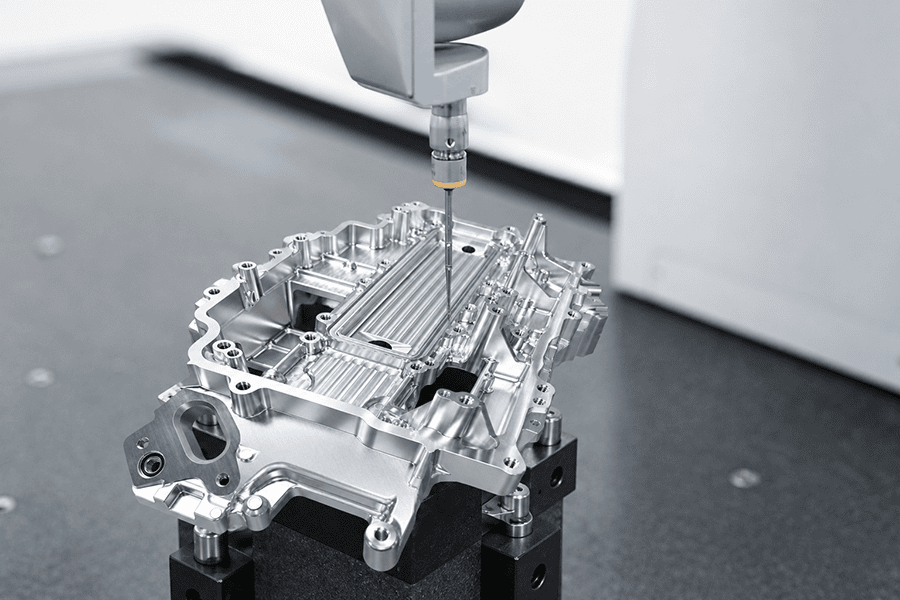
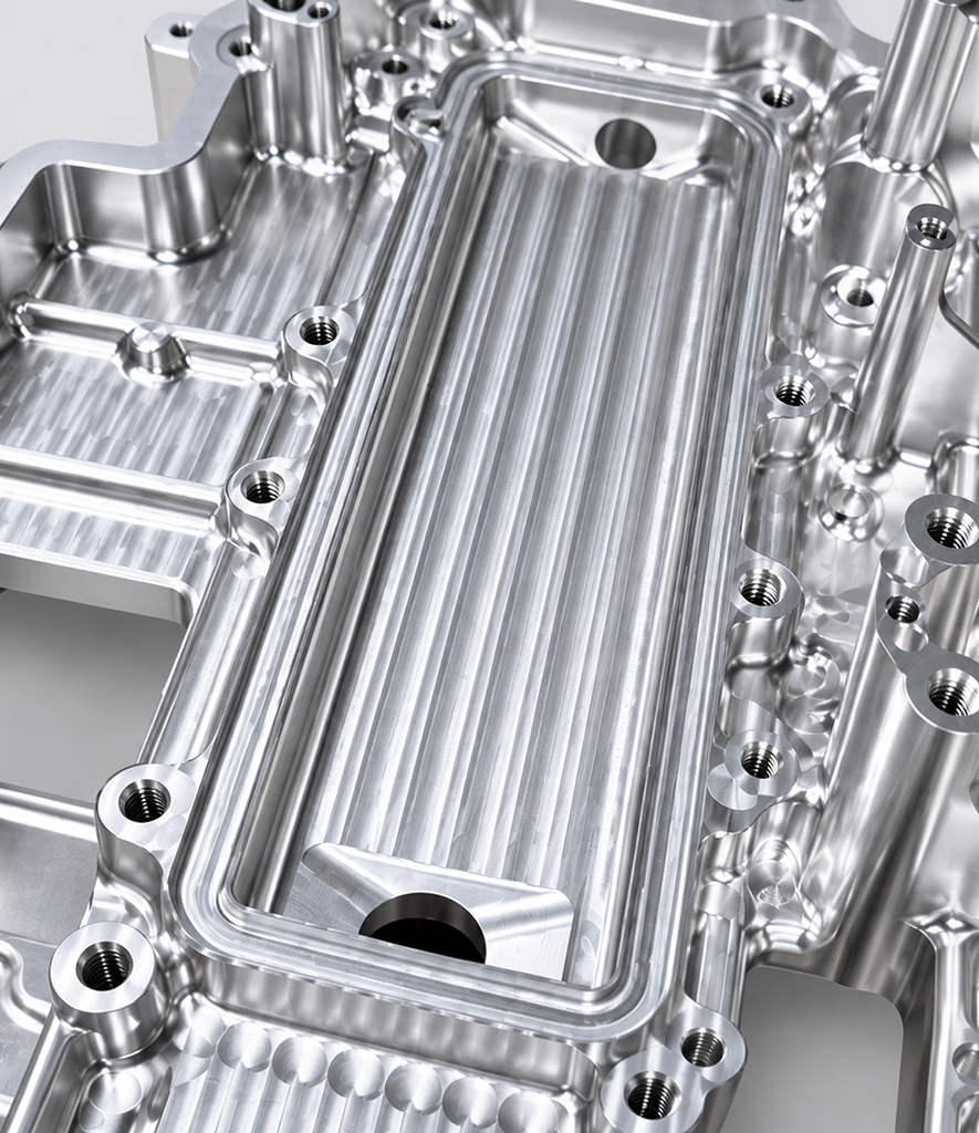
A 6061-T6 aluminum hollow cavity, 300×280×260mm, machined on all six faces with internal pocket structures and 5mm walls, passed CMM inspection with flatness measured at 0.02 to 0.04mm against a drawing requirement of ≤0.05mm. Perpendicularity measured 0.02 to 0.04mm against the same ≤0.05mm tolerance. No chatter marks on any surface. No post-machining warp. FAI passed on first submission. 100% yield. The part shipped within two weeks of CAD receipt.
The drawing specified a one-piece hollow enclosure with six-face machining, internal pockets, and 5mm walls throughout, machined from solid 6061-T6 billet to a flatness tolerance of ≤0.05mm and a perpendicularity tolerance of ≤0.05mm. That combination of thin walls, large material removal volume, and dimensional accuracy across all six faces breaks most CNC programs on aluminum alloy housings.
6061-T6 aluminum was specified for its strength-to-weight ratio and machinability in a defense electronics application where the cavity serves as both a structural enclosure and an EMI shielding body. Casting was ruled out. The internal pocket geometry and wall thickness uniformity at 5mm demanded machining precision that die casting does not hold without secondary operations that reintroduce stress. Sheet metal fabrication with welded seams was ruled out because weld distortion on a 5mm-wall enclosure exceeds the 0.05mm flatness requirement, and weld zones break EMI shielding continuity. 5-axis aluminum CNC machining from solid billet was the only route that held dimensional accuracy and wall uniformity on this form.
1. Why conventional CNC machining loses control on thin-wall 6061 aluminum cavities
On a 4-axis CNC setup, this cavity needed three separate clamping operations to access all six faces. Each re-clamp introduced positional error and changed the stress state of the workpiece. The third setup cut against datum surfaces that had already shifted from residual stress release during the first two operations. Flatness drifted beyond 0.12mm and perpendicularity exceeded 0.10mm after the third clamping on the trial pieces run before the 5-axis rework.
Sequencing was the second failure source. A single roughing-to-finishing pass on each face removes bulk material in one operation, and concentrates deep cutting stress in the thin walls. 6061-T6 is precipitation-hardened and dimensionally stable relative to pure aluminum, but stress still builds fast when the material removal ratio is high. Over 80% of the billet volume was removed on this part. That volume of stock removal on 5mm walls, without intermediate stress release, produced measurable wall deflection within minutes of unclamping. Flatness readings on the first trial piece exceeded 0.15mm.
Chatter marks appeared on the pocket floors where the tool forced the thin wall into resonance. The mechanism: the end mill engages the 5mm wall, the wall deflects away, springs back, and re-engages at a higher impact load. This cycle prints a ripple pattern that violates the flatness tolerance and leaves tool marks that polishing does not remove. On the conventional 4-axis approach, chatter appeared on three of six faces. Both trial pieces scrapped.
Engineering note: for hollow aluminum enclosures with wall thickness below 8mm, overall dimensions above 250mm in any axis, and flatness requirements below 0.08mm, a multi-stage stress-relief strategy with reduced clamping setups fits the geometry better than a direct rough-to-finish sequence on a 4-axis machine. The combined effect of multiple re-clamps and concentrated roughing stress exceeds the tolerance budget before the finishing pass begins.
2. Four process locks that held geometry on this 6061-T6 aluminum enclosure
Each lock addresses one of the failure modes from the 4-axis trial: setup shift, sequencing stress, asymmetric stock, and chatter onset. Removing any one re-exposes the finishing pass to the same error magnitude that scrapped the trial pieces.
2.1 5-axis CNC machining cut clamping from three setups to two
The 5-axis CNC machining center accessed five faces in a single setup. One re-clamp handled the sixth face. Three setups down to two. That one fewer clamp removed the largest single source of positional error on this geometry. The third-setup datum shift measured 0.10mm on the 4-axis approach dropped out entirely.
2.2 Three-stage cutting with cooling dwells for stress relief
The process split into three stages: roughing, intermediate semi-finishing, and final finishing. Natural cooling dwells sat between each stage.
Roughing left 0.5 to 0.8mm stock per side. After roughing, the part sat at ambient temperature. Residual stress from heavy material removal redistributed and partially released through natural aging during that dwell. The intermediate semi-finishing pass then removed 0.4 to 0.7mm per side, bringing the part close to final dimension while bleeding a second round of residual stress. Another cooling dwell. The final finishing pass cut at 0.1mm depth per side, working against a stress-stable substrate with almost no remaining stock.
According to EPOC CRAFTER’s process planning lead: “We measured the blank after roughing. Stress release had already moved the part 0.06mm out of flat. After the first dwell and semi-finish, that dropped to 0.02mm. By the time the finishing pass ran, the substrate was stable enough that the 0.1mm cut did not add measurable distortion.”
2.3 Uniform stock allowance kept stress release symmetric
Each cutting stage left a uniform stock allowance on all surfaces, not just the surfaces being finished next. Roughing left 0.5 to 0.8mm evenly on every wall and face. When stress released during the cooling dwell, it released symmetrically across the cross-section. No side had less remaining stock to pull the part toward it. Semi-finishing followed the same rule, leaving a uniform 0.1mm finishing allowance on every surface before the final cut.
2.4 Finishing depth held at 0.1mm, validated against the chatter threshold
According to EPOC CRAFTER’s CNC process engineer: “On the 5mm walls, we held the finishing pass at 0.1mm depth of cut. At 0.2mm, wall vibration amplitude crossed into the chatter zone on the pocket floors. We ran a test pass on the semi-finished part to confirm the threshold before touching the final surfaces.”
At 0.1mm depth of cut, radial cutting force on the 5mm wall stayed below the elastic deflection threshold. The wall absorbed the cutting load without deflection. No ripple pattern. No tool marks visible on any of the six machined faces after deburring.
Engineering note: for thin-wall aluminum pockets with wall thickness below 8mm and pocket depth exceeding 50mm, finishing depth of cut needs validation against the wall deflection threshold on the actual workpiece geometry before the finishing program runs. Chatter onset varies with pocket aspect ratio, wall height, and residual stress state after semi-finishing. Published feed-rate tables do not account for these part-specific variables.
3. CMM inspection results on the 6061-T6 aluminum housing
All six machined faces went through full-dimension CMM inspection against the drawing callouts, with the flatness tolerance and perpendicularity zones set per ASME Y14.5-2018. Numbers below are measured on this part, not typical values from the material data sheet.
| Attribute | Drawing requirement | Measured on this part | Engineering note |
| Flatness | ≤0.05mm | 0.02 to 0.04mm | Below 0.04mm on a 300mm-span thin-wall cavity, the dominant residual error source shifts from machining stress to thermal drift during inspection. |
| Perpendicularity | ≤0.05mm | 0.02 to 0.04mm | 5-axis two-setup approach eliminated the datum shift that drove perpendicularity beyond 0.10mm on the 4-axis three-setup sequence. |
| Chatter marks | None permitted | No chatter marks on any face | 0.1mm finishing depth of cut stayed below the 5mm wall deflection threshold. |
| Wall thickness uniformity | 5mm nominal | Uniform across all walls | Three-stage cutting with uniform stock allowance prevented asymmetric wall thinning. |
| First article inspection (FAI) | Pass | Passed full-dimension CMM, first submission | FAI report per AS9102, 6061-T6 material certificate, and CMM report delivered with shipment. |
| Yield | 100% | Part shipped | Zero scrap. Conventional 4-axis approach scrapped both trial pieces. |
Engineering note: on thin-wall aluminum cavities with wall thickness below 8mm and flatness requirements below 0.05mm across spans above 250mm, the four-lock sequence (reduced clamping setups on 5-axis, three-stage cutting with cooling dwells, uniform stock allowance, and validated finishing depth of cut) is the minimum sequence that holds this tolerance. Removing any single stage re-exposes the finishing pass to a stress or positional error magnitude that exceeds the tolerance budget.
4. Which aluminum enclosure geometries this sequence fits, and where it needs modification
The four-lock deformation control sequence applies to aluminum alloy enclosures (6061-T6, 7075-T6, 6082-T6) with wall thickness below 8mm, overall dimensions above 250mm, internal pocket structures requiring multi-face machining, and flatness or perpendicularity tolerances below 0.08mm. Alloy choice between 6061 vs 7075 aluminum shifts the cooling dwell length: 7075-T6 stores more residual stress under the same material removal ratio and needs 30 to 50% more dwell time between stages. Defense electronics housings, avionics enclosures, RF shielding cavities, semiconductor equipment frames, and telecom base station chassis sit inside this envelope. Programs that stay under 200 pieces per year fit the low-volume aluminum CNC machining model without amortizing dedicated tooling.
Two part shapes need a modified approach. Enclosures with wall thickness below 3mm need vacuum fixture support during finishing. At 3mm the wall stiffness drops below the deflection threshold even at 0.1mm depth of cut, and no stress-relief sequence compensates for a wall that flexes during the cut itself. Parts with asymmetric pocket distributions (one side heavily pocketed, the other solid) need bilateral roughing sequencing to balance the stress field across the asymmetric cross-section. That adds a fifth lock.
The stress management strategy gets defined during the DFM review, before the CAM program is written, not retrofitted after the first article fails inspection.
5. FAQ: 6061-T6 aluminum CNC machining questions
5.1 Why does 6061-T6 aluminum warp after CNC machining thin-wall enclosures?
6061-T6 builds residual stress during heavy material removal. Over 80% of the billet volume was cut away to form the 5mm walls on this part. The stress field stored in those walls is asymmetric and unstable. Upon unclamping, the walls release stress by deflecting. On enclosures above 250mm, deflection exceeds tight flatness tolerances within minutes. Prevention needs material removal distributed across multiple stages with cooling dwells, so stress releases incrementally, not all at once after the final cut.
5.2 How do chatter marks form on thin-wall aluminum pocket floors, and can they be removed?
Chatter forms when cutting force exceeds the elastic stiffness of the thin wall. The wall deflects away from the cutter, springs back, and re-engages at a higher impact load. This vibration cycle prints a ripple pattern on the machined surface. On 5mm-wall aluminum pockets, ripple depth measured 0.03 to 0.08mm on our trial pieces, which means the flatness tolerance is consumed by chatter alone. The marks do not come out with polishing; removing them takes cutting below the ripple depth, which violates the wall thickness. The fix is upstream: validate finishing depth of cut against the wall deflection threshold on the actual part before running the finishing program.
5.3 Why 5-axis over 4-axis for six-face aluminum cavity machining?
A 4-axis machine needs three separate clampings to access all six faces. Each re-clamp shifts the datum by the fixturing repeatability error and changes the stress state of the partially-machined workpiece. A 5-axis center reaches five faces in one setup, cutting to two clamps total. On this program, that reduction eliminated the largest single source of perpendicularity error. The third-setup datum shift measured 0.10mm on the 4-axis approach dropped out entirely.
5.4 What documentation ships with defense-grade CNC aluminum parts?
Each shipment carries a first article inspection (FAI) report per AS9102, a CMM full-dimension inspection report, and a 6061-T6 raw material certificate with traceable mill heat number. The quality system operates under ISO 9001, with AS9100 compliance available for aerospace and defense programs.
Client Info
From: Israel
Industry: Defense (electronics enclosure / cavity housing)
Solution: One 6061-T6 aluminum CNC machining cavity, 300×280×260mm, 5-axis machined from solid billet, six-face machining, flatness 0.02 to 0.04mm (spec ≤0.05mm), perpendicularity 0.02 to 0.04mm (spec ≤0.05mm), zero chatter marks, 100% yield, FAI passed first submission.
Processes: 5-axis CNC machining (two setups), three-stage cutting (roughing + intermediate semi-finishing + finishing) with natural cooling dwells, uniform stock allowance strategy, 0.1mm finishing depth of cut, CMM full-dimension inspection.
Ready to Quote Your CNC Prototype?
Upload your STEP file and get a DFM review + quote within 12 hours.
No tooling cost. Minimum 1 part.
