

Dewey Wu General Manager & senior mechanical engineer at EPOC CRAFTER, 15 years in design engineering, quality, and metallurgy. Hands-on across CNC machining, metalwork, sheet metal, and prototyping (subtractive + 3D printing).
Engineering drawing tolerances are the numeric limits set per feature that decide whether a machined part passes inspection or gets scrapped, defined against ISO 2768-1:1989 for defaults, ISO 286-1:2010 for fits, and ASME Y14.5-2018 or ISO 1101:2017 for GD&T. On a 30 mm feature in Al 6061-T6, an ISO 2768-m note gives you ±0.1 mm at no added cost, while an H7 bearing bore at Ø25 (±0.021 mm) runs 3 to 5 times higher per feature to hold and verify. Under-specify and the parts do not assemble. Over-specify and you pay for precision no one uses.
Eight factors move the answer: material (6061-T6 holds tighter than PA6), geometry (300 mm parts drift more than 30 mm parts), feature type (a slip fit needs ISO 286, a bolt clearance hole does not), process route (3-axis milled vs reamed vs ground), setup and fixturing, surface finish (Ra 3.2 μm as-milled vs Ra 0.8 μm turned), quantity, and inspection method (caliper vs CMM at 20°C per ISO 1:2016 reference temperature).
The guide below gives you the Three-Layer Tolerance Ladder EPOC engineers apply on every quote, a Feature-Type decision table, a cost ladder tied to real quote data, three copy-paste title block templates, and a 12-point pre-release checklist.
1. The Three-Layer Tolerance Ladder
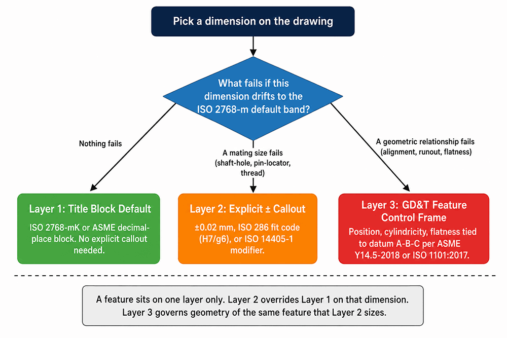
The Three-Layer Tolerance Ladder places every dimension on a CNC drawing into one control level. Layer 1 catches uncritical sizes through a title block note. Layer 2 tightens a size that mates or seals. Layer 3 governs geometry that a size alone cannot control.
You pick the layer once per feature, using one failure test: what breaks if the number drifts to the edge of the ISO 2768-1:1989 medium-class band? Nothing breaks means Layer 1 covers it. A mating size breaks (shaft into hole, pin into locator, thread engagement) means Layer 2. A geometric relationship breaks (hole pattern misalignment, sealing face rocking, bearing bore runout) means Layer 3. A feature sits on one layer only; Layer 2 overrides Layer 1 on that dimension, and Layer 3 governs the geometry of the same feature that Layer 2 sizes.
1.1 Layer 1: The title block default
Layer 1 is the note in your title block that reads “Unless otherwise specified, tolerances per ISO 2768-mK” or the ASME equivalent (±.005 in for 3-decimal, ±.010 in for 2-decimal, ±1° angular per ASME Y14.5-2018). One line covers every dimension you did not tighten explicitly.
Under ISO 8015:2011 §5.1 Invocation Principle, calling any part of the ISO GPS system pulls in the whole framework, so the title block note also imports the ISO 1:2016 reference temperature of 20°C and the ISO 14253-1 measurement decision rules. For the four class tables and the 2026 status of ISO 2768-1 and ISO 22081:2021 that replaced ISO 2768-2, read our ISO 2768 general tolerances guide.
1.2 Layer 2: The explicit ± callout
Layer 2 replaces the default on a single dimension. Write ±0.02 mm next to a Ø25 bearing bore and Layer 1 no longer governs that number. Under ISO 14405-1:2016 the ± callout defaults to a two-point size: the gauge reads across two opposing points, and the rest of the profile is not held by that value.
A two-point Ø25 h7 shaft can pass its size check and still be lobed enough to fail assembly in a rotating fit. Layer 2 alone is not enough for round parts that rotate under load. For fit intent between mating pairs, replace ± with an ISO tolerance class code (Ø25 g6 shaft into Ø25 H7 hole is a running clearance fit); see our ISO 286 fits for shaft and hole guide for the full designation logic and CNC-achievable IT grades without grinding.
1.3 Layer 3: The GD&T feature control frame
Layer 3 controls geometry when size cannot. A ± tolerance controls how big a hole is. A position feature control frame controls where the hole is relative to a datum reference frame. Under ASME Y14.5-2018 §6.4, the frame carries five compartments: geometric symbol, tolerance value with modifiers, and up to three datum references in precedence order. ISO 1101:2017 §8 matches the syntax, with three extra callouts (concentricity, coaxiality, symmetry) ASME does not carry as separate symbols.
ISO 5459:2024 §3.5 to §3.7 defines the primary, secondary, and tertiary datums the frame anchors to. ISO 2692:2014 §0.2 adds the Ⓜ modifier when the tolerance grows as the feature departs from maximum material condition; that is how you buy back tolerance on bolt-hole patterns without loosening the fit. ISO 2692:2014 §0.3 defines the least material requirement Ⓛ for the opposite case, controlling minimum wall thickness against burst or breakout. Neither modifier applies to threaded features.
Datum selection follows function, not the alphabet. If the part bolts to a flat plate, that plate is datum A. If it locates against a pin, the pin bore is datum B. If it clocks against a slot, the slot is datum C. Picking A, B, C by the alphabetical order of surfaces on the CAD model is the most common failure pattern documented in the Practical Machinist and Hardware is Hard forums.
According to Dewey Wu, when GD&T frames climb past roughly 15% of the dimensions on a CNC drawing, the drawing is over-specified against the part’s function on almost every job we quote, and each extra Layer 3 callout adds inspection time that shows up in the price.
2. Feature-Type to Ladder Decision Table
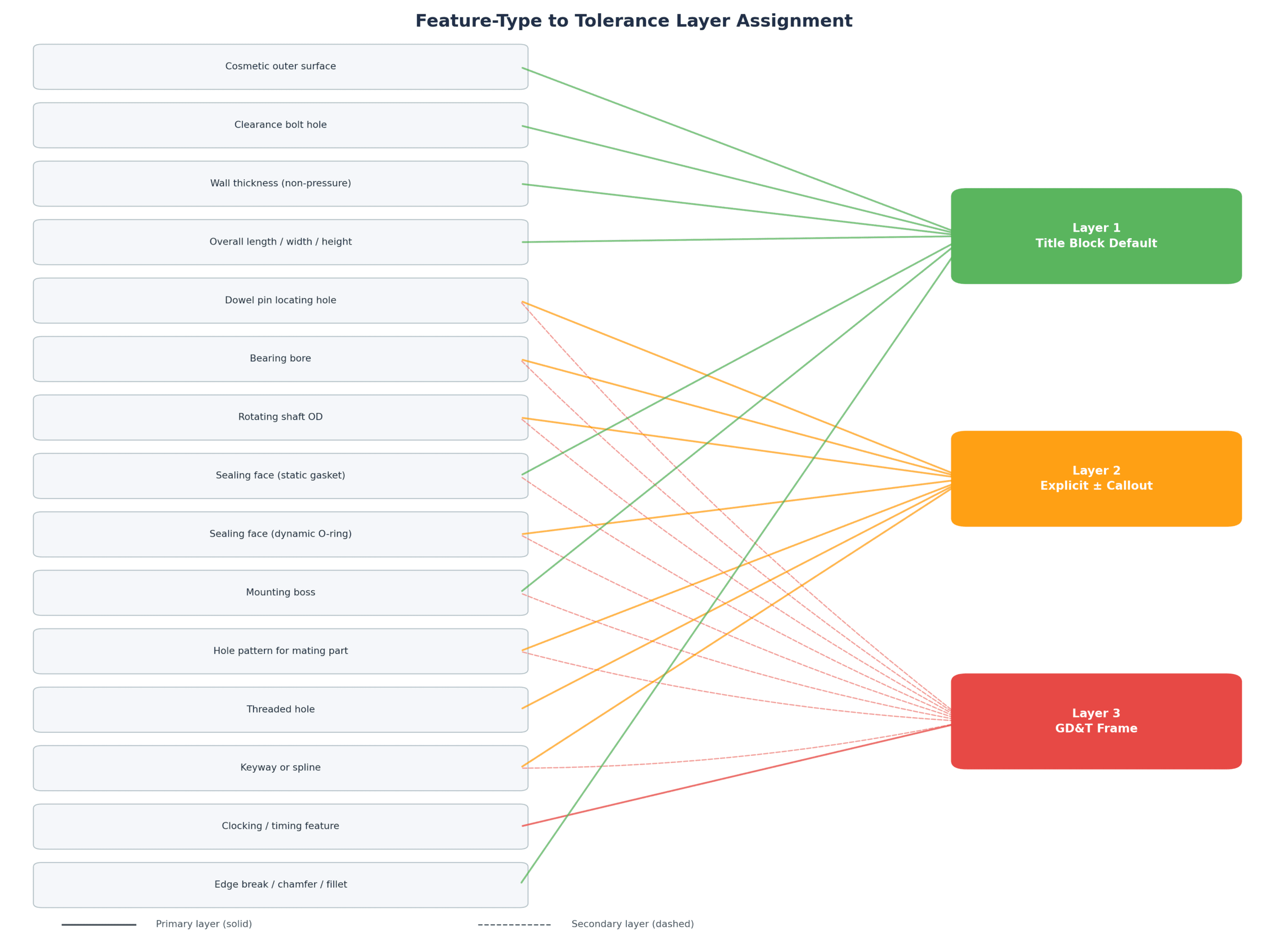
The Feature-Type to Ladder Decision Table maps each common CNC feature to the tolerance layer that governs it, a starting numeric band, and the failure mode that pushes the feature up a layer. Use it as the first pass on a new drawing to sort what stays on Layer 1 from what needs Layer 2 or Layer 3.
Every row is one feature type. The Layer column names the lowest layer that will still catch the failure mode; features that also need geometric control show a second layer in parentheses. The Starting Band column gives a reference value from a common CNC process without grinding, in Al 6061-T6, on a part under 100 mm.
| Feature type | Layer | Starting band (Al 6061-T6, sub-100 mm) | Push tighter when |
| Cosmetic outer surface | Layer 1 | ISO 2768-m or ±0.1 mm | A mating trim ring rides on it |
| Clearance bolt hole | Layer 1 | ISO 2768-m diameter | A dowel-located pattern is present |
| Wall thickness (non-pressure) | Layer 1 | ISO 2768-m | Part sees hoop stress, jump to Ⓛ per ISO 2692:2014 §0.3 |
| Overall length, width, height | Layer 1 | ISO 2768-m | Part slots into a housing pocket under 0.2 mm nominal clearance |
| Dowel pin locating hole | Layer 2 | Ø h7 or reamed to ±0.013 mm at Ø6 | Pin transmits load or clocks the assembly, add Layer 3 position |
| Bearing bore | Layer 2 + Layer 3 | H7 diameter plus cylindricity 0.005 mm | Radial load exceeds bearing dynamic rating or shaft speed passes 3000 rpm |
| Rotating shaft OD | Layer 2 + Layer 3 | g6 diameter plus cylindricity 0.005 mm | Rotating fit with seal, add Ra callout |
| Sealing face (static gasket) | Layer 1 + Layer 3 | ISO 2768-m diameter, flatness 0.05 mm on the seat | Gasket thinner than 1 mm or seal fluid pressure exceeds 5 bar |
| Sealing face (dynamic O-ring) | Layer 2 + Layer 3 | ±0.05 mm groove width, flatness 0.02 mm, Ra 0.8 μm | Refer to O-ring supplier chart for the specific ring |
| Mounting boss | Layer 1 + Layer 3 | ISO 2768-m plus perpendicularity 0.1 mm to seating face | Boss carries preload from a bolted joint |
| Hole pattern for a mating part | Layer 2 + Layer 3 | ± diameter plus position 0.2 Ⓜ to A B C | Assembly bolted through both parts, pattern over 100 mm |
| Threaded hole | Layer 2 (thread class) | M6x1-6H, thread depth callout separately | Blind hole under 1.5×D engagement, see tapped hole callouts |
| Keyway or spline | Layer 2 + Layer 3 | ±0.05 mm width plus parallelism 0.05 mm to shaft axis | Torque-carrying joint above 20 Nm |
| Clocking or timing feature | Layer 3 | Position 0.1 to a datum axis | Every part with rotational alignment on assembly |
| Edge break, chamfer, fillet | Layer 1 | Note “break sharp edges 0.2 to 0.5 mm” | Cosmetic edge visible to customer or mating O-ring rolls over it |
Two rules override the table. First, a feature that appears in a mating pair inherits the tighter partner’s ladder assignment: a clearance hole opposite a dowel pin becomes a dowel-pattern feature and jumps from Layer 1 to Layer 2 plus 3.
Second, a feature that repeats in a pattern of six or more (a fastener grid, a heat sink pin field, a lightening hole array) needs a single position callout with Ⓜ instead of individual ± callouts, per ISO 2692:2014 §0.2. Individual ± values on a large pattern accumulate into a stack-up the assembly cannot absorb. For CNC design rules that feed these decisions, see our DFM design guidelines for CNC parts.
3. What Over-Tolerancing Costs You
Over-tolerancing raises the unit price through six mechanisms: gauge tier upgrades, ISO 14253-1 measurement uncertainty subtracted from the acceptance band, slower finish passes, secondary operations, first-article documentation load, and scrap risk from a shrinking process capability window. Industry cost benchmarks show 15% to 400% price uplift tied to how tight you push.
Industry cost benchmarks published by comparable CNC platforms map tolerance tightness to price uplift over a baseline of ±0.13 mm (±0.005 in).
| Tier | Band | Price uplift vs baseline | Process shift |
| Baseline | ±0.13 mm (±0.005 in) | 1.0× | 3-axis mill, caliper inspection |
| Precision | ±0.05 mm (±0.002 in) | +15% to +30% per feature | Micrometer inspection, slower finish pass |
| High Precision | ±0.025 mm (±0.001 in) | +40% to +80% | Bore gauge, reamed or bored |
| Ultra Precision | ±0.013 mm (±0.0005 in) | +100% to +200% | CMM required, tighter fixturing |
| Ground | ±0.005 mm (±0.0002 in) | +200% to +400% | Grinding or lapping, air gauge |
The step from ±0.005 in to ±0.0005 in stacks two tiers, not one four-times increment. Under ISO 14253-1, invoked through ISO 8015:2011 §5.1 whenever the drawing references any ISO GPS standard, measurement uncertainty is subtracted from the specified band to form the acceptance zone. A ±0.02 mm callout inspected on a micrometer with ±0.005 mm uncertainty gives a real acceptance band closer to ±0.015 mm and drives scrap on parts that would have shipped under a looser value.
Run three tests before the RFQ leaves your desk. The 80/20 test: 80% of dimensions on a well-designed part sit at Layer 1 default, 10% to 20% carry Layer 2 ± callouts, under 15% carry Layer 3 frames. The repeated-value test: any tolerance value appearing on more than five dimensions is a candidate for Layer 1.
The “why is this tight” test: for every callout tighter than the block default, write a one-line function reason in your DFM notes (bearing runout, sealing face, dowel locate, thread engagement). A tolerance that cannot be justified in five words is a habit copied from a prior drawing.
According to Dewey Wu, a drawing that lands at EPOC with more than 15% of its dimensions carrying Layer 3 GD&T callouts almost always returns for engineering review before we release the quote. The review adds one to two days before the price is stable, and it retires two or three callouts per hundred dimensions.

4. Title Block Templates You Can Copy Today
Three title block templates cover almost every CNC drawing you send out. Template A follows the ISO route, Template B follows the ASME decimal-place route, and Template C is a bilingual hybrid for parts routed to both US and offshore shops. Paste one into your drawing template and Layer 1 is done for every future drawing.
4.1 Template A: ISO Metric (SolidWorks, Autodesk Inventor, PTC Creo)
UNLESS OTHERWISE SPECIFIED:
1. TOLERANCES PER ISO 2768-mK
2. GEOMETRICAL TOLERANCING PER ISO 1101:2017
3. DATUMS PER ISO 5459:2024
4. SIZE MODIFIERS PER ISO 14405-1:2016
5. SURFACE TEXTURE PER ISO 21920-1:2021, DEFAULT Ra 3.2 μm
6. METRIC THREADS PER ISO 261, TOLERANCE CLASS 6H/6g
7. EDGES PER ISO 13715, BREAK SHARP EDGES 0.2 TO 0.5 mm
8. DIMENSIONS IN mm, INSPECTION AT 20°C PER ISO 1:2016
9. DRAWING PER ISO 128-1:2020
4.2 Template B: ASME Imperial (US shops, aerospace, defense)
UNLESS OTHERWISE SPECIFIED:
1. DIMENSIONS IN INCHES
2. TOLERANCES: .X = ±.030 .XX = ±.010 .XXX = ±.005 .XXXX = ±.0005 ANGULAR = ±1°
3. INTERPRET DIMENSIONS AND TOLERANCES PER ASME Y14.5-2018
4. DRAWING PRACTICES PER ASME Y14.100-2017
5. SURFACE FINISH PER ASME Y14.36M-1996, DEFAULT 125 μin Ra
6. THREADS PER ASME B1.1, CLASS 2B/2A
7. BREAK SHARP EDGES .010 TO .020
8. INSPECTION AT 68°F PER ASME Y14.5-2018
4.3 Template C: Bilingual hybrid (routed to both US and offshore CNC)
UNLESS OTHERWISE SPECIFIED:
1. DIMENSIONS IN mm [inches in brackets, reference only]
2. TOLERANCES PER ISO 2768-mK
3. GEOMETRICAL TOLERANCING PER ISO 1101:2017 OR ASME Y14.5-2018
4. IN CASE OF CONFLICT, ISO 1101:2017 SHALL GOVERN
5. SURFACE TEXTURE PER ISO 21920-1:2021, DEFAULT Ra 3.2 μm
6. METRIC THREADS PER ISO 261, TOLERANCE 6H/6g
7. BREAK SHARP EDGES 0.2 TO 0.5 mm
8. INSPECTION AT 20°C PER ISO 1:2016
9. DIMENSIONS APPLY AFTER SURFACE FINISHING UNLESS NOTED
4.4 The two lines that end the most drawing arguments
Line 4 in Template C (ISO governs on conflict) ends the ASME versus ISO GD&T dispute that surfaces on every bilingual drawing. Layer 1 dimensions still ride on top of a surface texture callout; for the Ra values each CNC process actually delivers as-machined, see our surface roughness chart for machined parts. Line 9 (dimensions apply after finishing) matters for any part that gets anodized, plated, or coated. Type II anodize on 6061 adds about 5 to 20 μm per surface, doubled across a hole diameter, which moves a bore by 10 to 40 μm.
ASME Y14.5-2018 §4.1(f) allows non-mandatory processing dimensions, but the finished dimension is the one the customer inspects. Naming it on the block ends the argument at incoming QC on every future drawing. For the anodize-driven dimension shift and pre-anodize compensation rules, see our machining 6061 for anodize guide.
5. Before You Release the Drawing: The 12-Point Checklist
A tolerance you cannot inspect is a tolerance you cannot trust. Before releasing the drawing, match every callout to a gauge that can read it under ISO 14253-1 acceptance rules, name the inspection temperature (20°C per ISO 1:2016 or 68°F per ASME Y14.5-2018), and run the 12-point checklist below.
Machinery’s Handbook 32nd pp. 691 to 728 lays out the gauge accuracy ladder. A digital caliper reads to about ±0.02 mm on shop-floor use, a micrometer to about ±0.005 mm on a hardened anvil, a bore or air gauge to about ±0.002 mm zeroed, a CMM to about ±0.002 mm per point plus datum-referenced computation no hand tool can capture. A Layer 2 callout tighter than caliper resolution forces a micrometer setup and adds inspection time. A Layer 3 callout with a datum reference frame requires a CMM.
Temperature matters as much. Al 6061-T6 expands about 23.6 μm/m/°C. A 10°C swing above the ISO 1:2016 reference of 20°C shifts a 100 mm feature by 23 μm and a 300 mm feature by 71 μm. Stainless 304 and 316 sit at 16 to 17 μm/m/°C; Ti-6Al-4V at 9 μm/m/°C. Name the inspection temperature on the block and the argument ends at incoming QC.
Run each drawing through the 12 checks below.
1. Title block carries a Layer 1 tolerance note (ISO 2768 class or ASME decimal-place block)
2. Title block names the geometric tolerancing standard (ISO 1101 or ASME Y14.5)
3. Title block names the inspection temperature (20°C or 68°F)
4. Title block states whether dimensions apply before or after surface finishing
5. Every fit that mates carries an ISO 286 code or an equivalent ± callout on both parts
6. Every Layer 3 frame carries a primary, secondary, and tertiary datum in precedence order
7. Datum letters match the mating assembly, not the alphabet
8. Every ± value tighter than the block default has a one-line function reason in DFM notes
9. Layer 3 frames sit under 15% of total dimensions (higher ratios trigger a review)
10. Every threaded hole names the thread designation and the depth separately
11. Every surface finish callout uses ISO 21920 or ASME Y14.36M symbols with a Ra value
12. No dimension is scaled or measured from the drawing; every dimension is explicit per ASME Y14.5-2018 §4.1(b)
For the full standard-by-standard breakdown, see our tolerances and standards resource hub. The downloadable version of this 12-point checklist is linked at the end of this article.

6. Frequently Asked Questions
6.1 Do I need a drawing if I have a STEP file?
Yes in most cases. A STEP file carries geometry and nominal dimensions, but not tolerances, surface finish callouts, thread designations, or datum references. ASME Y14.5-2018 §4.1(a) and ISO 128-1:2020 §1 both treat the drawing as the full workpiece specification, meaning the tolerance envelope that decides pass or fail lives on the drawing, not in the CAD body. A STEP-only quote at EPOC returns with default assumptions applied (ISO 2768-mK, Ra 3.2 μm, ISO 261 threads) and a request for the buyer to confirm each before cutting starts. That round-trip adds one to three days.
6.2 How many dimensions on a drawing should carry an explicit tolerance?
About 20% for a well-designed CNC part. The Three-Layer Tolerance Ladder maps roughly 80% of dimensions to Layer 1 (title block default), 10% to 15% to Layer 2 (explicit ± callouts on mating features), and under 15% to Layer 3 (GD&T frames on function-driven geometry). A drawing with tighter callouts on more than 30% of dimensions carries legacy callouts copied from prior revisions, cosmetic callouts on features no mating part touches, or over-tolerancing driven by CAD software defaults. Any of the three raises the quote without changing part function.
6.3 What happens if I do not specify a tolerance on a dimension?
The shop applies the Layer 1 default from the title block. A 30 mm feature under an ISO 2768-mK note receives ±0.2 mm on the medium class. Under an ASME decimal-place block, the same dimension inherits the band tied to its decimal places.
If the title block has no tolerance note at all, the shop applies its house default (at EPOC that is ISO 2768-mK for metric and ±0.1 mm for imperial), returns the drawing with the assumption marked, and holds the quote until the buyer confirms. Silent dimensions receive the coarsest band the block allows.
6.4 Does a tighter tolerance always cost more?
Almost always, and the increase is not linear. Moving from ISO 2768-m at ±0.1 mm to Precision at ±0.05 mm adds 15% to 30% per feature. Moving to ±0.025 mm adds 40% to 80%. Moving to ±0.013 mm adds 100% to 200%. Moving to a ground band at ±0.005 mm adds 200% to 400%. The uplift comes from six mechanisms: gauge tier upgrades, ISO 14253-1 acceptance zone shrinkage, slower finish passes, secondary operations like grinding or lapping, first-article documentation load, and scrap risk from a narrowing process capability window.
6.5 When should I use GD&T instead of a ± callout?
Use GD&T when the geometry of the feature matters more than its size. A ± callout controls how big a hole is. A position frame controls where the hole sits relative to a datum reference frame. A flatness frame controls how flat a sealing face is. If the failure mode is misalignment, rocking, runout, or hole-pattern stack-up, size alone cannot describe what “good” means.
Under ASME Y14.5-2018 §6.4 and ISO 1101:2017 §8, the feature control frame carries the symbol, tolerance zone, any material condition modifier, and the datum references that anchor the zone to a functional reference.
6.6 What is the difference between ISO 2768 and an ASME block tolerance?
Both cover unmarked dimensions on the drawing, but they route through different standards families. ISO 2768-1:1989 assigns a linear tolerance based on nominal size and class letter (f, m, c, v), independent of the decimal places written on the drawing. The ASME decimal-place block ties the tolerance to the decimal count on each dimension (X.X, X.XX, X.XXX) under ASME Y14.5-2018 practice.
ISO 2768 automatically invokes the full ISO GPS system through ISO 8015:2011 §5.1, meaning the ISO 1:2016 reference temperature and ISO 14253-1 acceptance rules come with the note. The ASME block does not carry that automatic invocation and requires the standards to be named explicitly.
6.7 Should the tolerance band apply before or after surface finishing?
Name it on the drawing. Anodizing, plating, powder coating, and passivation change the finished dimensions. A Type II anodize on 6061 adds about 5 to 20 μm per surface, which moves a hole diameter by 10 to 40 μm.
If the drawing does not name whether the ± band applies before or after finishing, the shop and the inspector disagree at incoming QC. ASME Y14.5-2018 §4.1(f) allows non-mandatory processing dimensions in a note, but the finished dimension is the one the customer inspects. Add “Dimensions apply after surface finishing unless noted” to your title block.
6.8 Can a CMM inspect every tolerance on my drawing?
No. A CMM reads to about ±0.002 mm per point and computes datum-referenced tolerance zones no hand tool can capture, which makes it the required inspection tool for Layer 3 GD&T frames. A CMM handles ±0.005 mm callouts on Layer 2 sizes reliably, but a hardened-anvil micrometer or bore gauge is faster for a straight diameter or plain length.
Callouts tighter than ±0.002 mm move to grinding, lapping, or air gauging, which are separate inspection setups with separate metrology. Every Layer 3 callout adds one CMM line item to the first article report and grows the inspection labor per part.
Related Resources
Related Article: ISO 286 fits explained for shaft and hole expands Layer 2 mating callouts into the H7/g6 designation system, clearance and interference calculations, and CNC-achievable IT grades without grinding.
Related Article: Surface roughness chart for CNC parts gives the Ra, Rz, and N-grade values each CNC process actually delivers as-machined, and how ISO 21920 accepts a single Ra callout under the maximum rule.
Related Standards Reference: ISO 2768 general tolerances covers the four class tables (f/m/c/v), the ISO 22081:2021 replacement of Part 2, and the 2026 revision that removes the -1 suffix.
Related Article: Metric thread chart and tapped hole callouts covers the M1.6–M100 sizes, tap drill diameters, the Four-Depth Rule for blind holes, and 6H/6g limits per ISO 965-2:2024.
Related Capability: CNC machining services at EPOC CRAFTER covers the shop capability window this article assumes: 3-axis and 5-axis milling, turning, and inspection tiers from caliper to CMM.
Related Material Guide: Machining 6061 for anodize covers the anodize-driven dimension shift referenced in §4.4 and §6.7, with per-thickness ranges and pre-anodize compensation rules.
Related Standards Reference: Tolerances and standards resource hub collects the ISO 286, ISO 2768, ISO 21920, and ASME Y14.5 references cited across this cluster, with revision status and cross-reference tables.
Ready to Quote Your CNC Prototype?
Upload your STEP file and get a DFM review + quote within 12 hours.
No tooling cost. Minimum 1 part.
