

Dewey Wu General Manager & senior mechanical engineer at EPOC CRAFTER, 15 years in design engineering, quality, and metallurgy. Hands-on across CNC machining, metalwork, sheet metal, and prototyping (subtractive + 3D printing).
CNC machining produces functional prototypes and low-volume parts with tolerances down to ±0.005mm, surface finishes from Ra 0.8μm, and no tooling cost. For hardware engineers sourcing 1 to 500 parts in metal or engineering-grade plastic, it covers the full range from first-article validation through bridge production.
Not every prototype belongs on a CNC machine. Eight factors determine whether CNC is the right call on a given job: material (metal or high-performance plastic vs. concept resin), geometry (prismatic vs. organic free-form), feature type (threads, bores, sealing faces vs. lattice or undercut-heavy forms), process route (3-axis, 4-axis, or 5-axis indexed milling, turning, or combined), setup and fixturing (part count vs. setup cost ratio), surface finish (Ra requirement and whether post-processing adds lead time), quantity (unit economics shift between 1 and 50 parts), and inspection method (visual pass, first-article report, or CMM with GD&T callouts).
This guide walks through each factor with specific numbers, a process comparison table, material selection logic, and a DFM checklist, so you can make the sourcing call before you send the file.
CNC prototype machining cuts a finished part directly from solid bar stock or plate using computer-controlled mills and lathes. No mold, no tooling deposit, no minimum order. You upload a CAD file, the machine runs the toolpath, and you get a part that carries the full mechanical properties of the chosen material.
That last point separates CNC from most additive processes. A 3D-printed part builds in layers, which introduces anisotropy: tensile strength along the Z-axis on an FDM part runs roughly 20 to 40 percent lower than on the XY plane. A CNC-machined part cut from Al 6061-T6 billet holds the same grain structure and heat-treat condition throughout. For functional testing, load bearing, pressure sealing, fatigue cycling, that homogeneity matters.
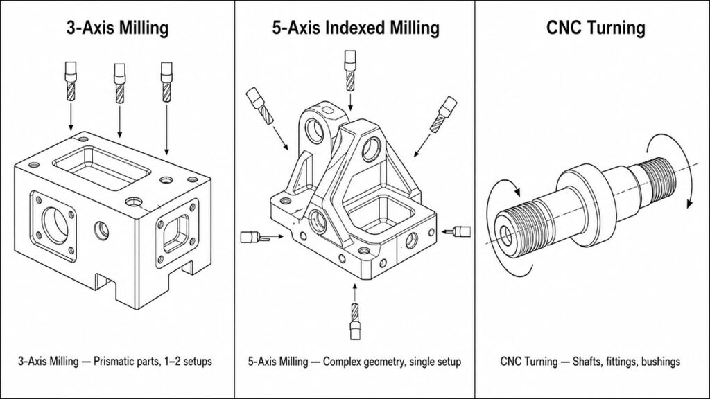
CNC prototype machining covers three main process routes:
3-axis milling handles prismatic parts with features on one to two faces. Setup is fast, cost is lower, and it works for the majority of brackets, housings, and plates.
4-axis and 5-axis indexed milling reaches features on multiple faces in a single setup. Fewer setups mean better positional accuracy between features and shorter lead time on complex geometries.
CNC turning and turn-mill produces cylindrical parts: shafts, fittings, threaded components, and bushings. A turn-mill center combines turning and milling in one setup, which holds concentricity between turned and milled features better than transferring between machines.
The process is subtractive: material comes off, not on. Geometry that traps the cutter, deep internal cavities with no access angle, true internal undercuts with no rotational access, requires either EDM or a redesign. Everything else is fair game.
2. When CNC Machining Is the Right Choice for Prototypes
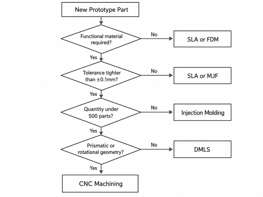
CNC is not the default answer for every prototype. It is the right answer when the part needs to perform, not just look right.
Use CNC machining when one or more of these conditions apply:
Material properties must match the production intent. Concept models can use any resin. Engineering validation prototypes cannot. If the part will be load-tested, pressure-cycled, thermally stressed, or installed into a mating assembly for fit verification, the material needs to be the real one: Al 6061-T6, SS 316L, Ti-6Al-4V, PEEK, or Delrin, not a photopolymer approximation.
Tolerances are tighter than ±0.1mm. SLA and MJF hold ±0.1 to ±0.2mm on a good day, with variation increasing on larger parts. CNC holds ±0.01mm as a standard capability, and ±0.005mm on critical features with proper fixturing and inspection. For sealing faces, press-fit bores, or any feature that mates with a purchased component, additive processes will not close that gap.
Surface finish has a functional requirement. A sealing groove needs Ra 0.8μm or better. A bearing bore needs Ra 1.6μm. Structural faces that will be anodized need Ra 1.6μm to get a uniform coating. FDM delivers Ra 6 to 13μm before post-processing. CNC delivers Ra 0.8 to 3.2μm off the machine, with Ra 0.4μm achievable on finish passes.
The part geometry is prismatic or rotational. CNC excels on parts built around flat faces, drilled holes, bored cylinders, and milled pockets. If the design is a free-form organic surface with no flat reference datum, SLA or DMLS may produce it faster and cheaper.
Quantity is between 1 and 500 parts. Below 5 parts, CNC and SLA are cost-competitive depending on material. Above 5 parts in metal, CNC unit cost drops faster than DMLS because there is no per-layer time penalty. Above 500 parts, injection molding or production machining with dedicated fixturing becomes more economical.
The part will transition to production. If the production process is CNC machining, prototyping in the same process validates the drawing, the tolerances, and the material behavior in a single step. Switching from SLA to CNC at production reveals DFM issues that should have been caught earlier.
When CNC is not the right choice
Organic geometries with no flat reference faces and no functional tolerance requirement belong on an SLA or PolyJet machine. Internal lattice structures, conformal cooling channels, and parts with true enclosed voids require additive processes. For concept models where only shape and proportion matter, FDM is faster and cheaper. For quantities above 1,000 in thermoplastic, injection molding’s per-part cost drops below any machining route.
For a full side-by-side breakdown of CNC against 3D printing and injection molding on cost, lead time, and tolerance, the next section covers the numbers directly. Readers sourcing for a specific industry application can visit EPOC CRAFTER’s CNC Machining service page.
3. CNC vs. 3D Printing vs. Injection Molding: Process Comparison
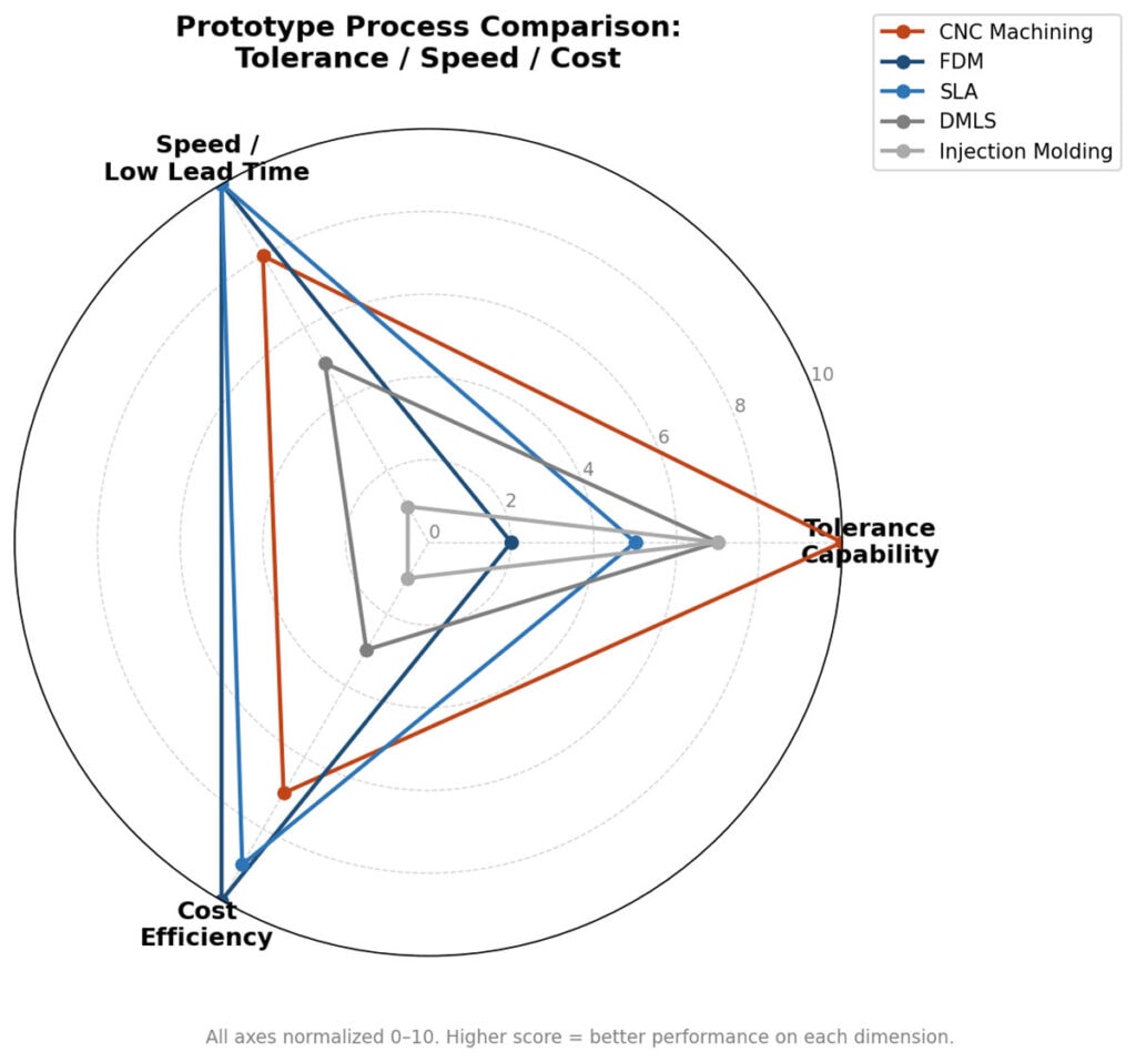
The table below covers the five processes engineers most commonly evaluate when sourcing prototypes and low-volume parts. Numbers are based on standard commercial capability, not best-case lab conditions. Decision meaning is included in each cell, not just the parameter.
TABLE 1: Prototype Process Comparison
| Parameter | CNC Machining | FDM | SLA | DMLS | Injection Molding |
| Standard tolerance | ±0.01mm | ±0.2–0.5mm | ±0.1–0.2mm | ±0.05–0.1mm | ±0.05–0.1mm (tool-dependent) |
| Tight tolerance | ±0.005mm on critical features | Not achievable | ±0.05mm with post-processing | ±0.02–0.05mm | ±0.025mm with steel tooling |
| Surface finish (as-built) | Ra 0.8–3.2μm | Ra 6–13μm | Ra 1.6–3.2μm | Ra 4–10μm | Ra 0.4–1.6μm (mold-dependent) |
| Material | Al 6061/7075, SS 303/316L, Ti-6Al-4V, PEEK, Delrin, Nylon | ABS, PC, ULTEM, PLA | Photopolymer resins only | SS 316L, Ti-6Al-4V, AlSi10Mg, Inconel | Most engineering thermoplastics, LSR |
| Material isotropy | Full isotropic, billet properties | Anisotropic, Z-axis 20–40% weaker | Anisotropic, UV-sensitive degradation | Near-isotropic, 97–99% dense | Isotropic, flow-dependent |
| Tooling cost | None | None | None | None | USD 3,000–15,000+ for aluminum tool |
| Lead time (1–5 parts) | 3–7 business days | 1–3 business days | 1–3 business days | 5–10 business days | 2–4 weeks (tooling) + 1–2 weeks parts |
| Unit cost at 1 part (metal) | USD 80–500 depending on complexity | Not applicable in metal | Not applicable in metal | USD 200–1,000+ | Not applicable at 1 part |
| Unit cost at 50 parts (metal) | USD 40–200 | Not applicable | Not applicable | USD 150–600 | USD 5–30 after tooling amortized |
| Minimum wall thickness (metal) | 0.5mm | 1.2mm | 0.6mm | 0.4mm | 0.8–1.5mm |
| Max part size (standard) | 600×600×300mm | 300×300×300mm | 350×350×400mm | 250×250×300mm | Limited by mold size |
| Functional testing suitability | High, full material properties | Low to medium, anisotropic | Low, brittle under load | High, near-production properties | High, production-equivalent |
| DFM feedback before production | Yes, at quoting stage | Minimal | Minimal | Yes, support structure design review | Yes, mold flow analysis |
| Transition to production | Direct if production is CNC | Requires process switch | Requires process switch | Possible to MIM at volume | Direct, same process |
Decision guidance
Pick CNC when the part requires functional testing in the production material, tolerances tighter than ±0.1mm, or a surface finish below Ra 3.2μm. The absence of tooling cost makes it the lowest-risk entry point for metal prototypes at quantities from 1 to 50.
Pick SLA when the part is a concept model or cosmetic prototype with no load requirement. Lead time and cost at 1 to 5 parts are hard to beat, and the surface finish is better than FDM out of the machine.
Pick DMLS when the geometry cannot be machined: internal channels, lattice structures, or enclosed voids. Expect higher cost and longer lead time than CNC for equivalent simple geometries.
Pick FDM for form-and-fit checks only. Do not use FDM parts for pressure, load, or fatigue testing without understanding the Z-axis strength penalty.
Pick injection molding when quantity exceeds 500 parts in thermoplastic and the design is frozen. The tooling cost is a fixed entry fee; below that quantity threshold it rarely makes economic sense unless the part cannot be machined or printed.
Material selection within CNC machining adds another layer to this decision. Al 6061-T6 and SS 316L behave very differently under the same tolerance callout, and the right material choice affects both machinability and post-processing options. For a deeper comparison on cost curves and tolerance data across these five processes, see the dedicated article: CNC Machining vs. 3D Printing for Prototypes. For engineers who have already selected their process and need capability specifications, visit EPOC CRAFTER’s materials page.
4. Materials for CNC Prototype Machining
Material choice on a prototype affects three things simultaneously: machinability (which drives cost and lead time), mechanical performance (which determines whether the part survives functional testing), and post-processing compatibility (which affects surface finish and dimensional stability after treatment). Picking the wrong material at the prototype stage means either retesting in production material later or carrying false confidence from a test that did not represent the real part.
The tables below cover the materials most frequently used at EPOC CRAFTER for prototype and low-volume orders, grouped by category.
TABLE 2: Aluminum Alloys
| Grade | Tensile Strength | Yield Strength | Machinability | Anodizing | Typical Prototype Use |
| Al 6061-T6 | 310 MPa | 276 MPa | Excellent | Yes, class I and II | Structural brackets, housings, heatsinks, general mechanical parts |
| Al 7075-T6 | 572 MPa | 503 MPa | Good | Yes, limited cosmetic quality | High-stress structural components, aerospace brackets, load-bearing arms |
| Al 5052-H32 | 228 MPa | 193 MPa | Good | Yes | Sheet metal-adjacent parts, corrosion-exposed housings |
| Al 2024-T3 | 483 MPa | 345 MPa | Good | Not recommended | Aerospace skins, fatigue-critical parts |
Engineering note: Al 6061-T6 covers 80 percent of general prototype work. Move to 7075-T6 only when the part will see sustained load above 250 MPa or when weight-to-strength ratio is the design constraint. Anodizing 7075 produces uneven color in complex geometries; if cosmetic finish matters, 6061 is the safer choice.
TABLE 3: Stainless Steels
| Grade | Tensile Strength | Yield Strength | Machinability | Corrosion Resistance | Typical Prototype Use |
| SS 303 | 620 MPa | 240 MPa | Excellent | Good | Shafts, fittings, turned components where finish is not critical |
| SS 304 | 515 MPa | 205 MPa | Good | Very good | Food contact, general corrosion-resistant housings |
| SS 316L | 485 MPa | 170 MPa | Moderate | Excellent, chloride resistant | Medical devices, marine, chemical exposure parts |
| SS 17-4 PH | 1,310 MPa (H900 condition) | 1,170 MPa | Moderate | Good | High-strength fasteners, aerospace, surgical tools |
Engineering note: SS 303 machines faster than 316L by a measurable margin. If the prototype only needs corrosion resistance in a mild environment and the drawing does not call out 316L specifically, 303 cuts cost and lead time. Do not substitute on medical or chloride-exposure parts.
TABLE 4: Titanium
| Grade | Tensile Strength | Yield Strength | Machinability | Typical Prototype Use |
| Ti-6Al-4V (Grade 5) | 950 MPa | 880 MPa | Difficult, requires reduced feed rates and sharp tooling | Aerospace brackets, medical implant components, high strength-to-weight structural parts |
| Ti Grade 2 (CP) | 345 MPa | 275 MPa | Moderate | Medical devices, corrosion-resistant non-structural parts |
Engineering note: Ti-6Al-4V costs significantly more to machine than aluminum, both in material cost and cycle time. On a prototype where the goal is dimensional validation rather than material validation, Al 7075-T6 runs a similar strength-to-weight check at lower cost. Reserve titanium for prototypes that will go directly into load testing or regulatory submission.
TABLE 5: Engineering Plastics
| Material | Tensile Strength | Max Service Temp | Machinability | Typical Prototype Use |
| Delrin (POM-C) | 68 MPa | 90°C | Excellent | Gears, bushings, sliding components, snap-fit parts |
| PEEK | 100 MPa | 250°C | Good, requires sharp tooling | Medical, aerospace, high-temperature structural parts |
| Nylon PA6 | 75 MPa | 80°C | Good | Housings, brackets, wear pads |
| UHMW-PE | 40 MPa | 80°C | Good | Bearing surfaces, food contact, wear liners |
| Polycarbonate (PC) | 60 MPa | 115°C | Good | Transparent covers, light guides, impact-tested housings |
Engineering note: PEEK at prototype stage is a material commitment, not just a process choice. At 3 to 6 times the material cost of Delrin, use it only when thermal or chemical exposure in the application genuinely requires it. For form-and-fit checks on a PEEK production part, machine the prototype in Delrin and validate geometry first.
TABLE 6: Other Metals
| Material | Key Property | Machinability | Typical Prototype Use |
| Brass C360 | Excellent machinability, good conductivity | Excellent | Electrical connectors, fittings, decorative hardware |
| Copper C110 | High thermal and electrical conductivity | Good | Heatsinks, bus bars, induction coils |
| Steel 1045 | Good strength, low cost | Good | Shafts, tooling fixtures, structural prototypes where weight is not a constraint |
| Steel 4140 | High strength, hardenable | Moderate | High-load shafts, gears, structural components |
TABLE 7: Post-Processing Compatibility by Material
| Process | Al 6061 | Al 7075 | SS 316L | Ti-6Al-4V | Delrin | PEEK |
| Anodize Type II | Yes | Yes, limited | No | No | No | No |
| Anodize Type III (hard coat) | Yes | Yes | No | No | No | No |
| Passivation | No | No | Yes | Yes | No | No |
| Electropolishing | No | No | Yes | Yes | No | No |
| Bead blast | Yes | Yes | Yes | Yes | No | No |
| Powder coat | Yes | Yes | Yes | No | No | No |
| Black oxide | No | No | Yes | No | No | No |
Engineering note: Anodizing adds 0.005 to 0.025mm per surface. On tight-tolerance features, this must be accounted for in the machined dimension before coating. If a bore is called out at H7 fit after anodizing, the machined bore needs to be cut larger by the anodize build-up amount. This is a common source of fit failure on first prototype orders.
5. Tolerances, Surface Finish, and Inspection Standards
Tolerance and surface finish are not interchangeable specs. Tolerance controls where material is. Surface finish controls what the surface looks like and how it functions. Both need to be called out explicitly on the drawing. A part with correct dimensions but wrong surface finish will fail a sealing test. A part with correct surface finish but wrong tolerances will fail an assembly fit check.
Tolerance Capability at EPOC CRAFTER
Standard machining tolerance: ±0.01mm This covers the majority of prototype work: housings, brackets, plates, and non-critical bores. No special setup required.
Precision tolerance: ±0.005mm Achievable on critical features with dedicated fixturing, temperature-controlled inspection, and finish passes. Apply this callout only where the function genuinely requires it. Every feature called out at ±0.005mm adds setup time and inspection time.
General tolerance standard: ISO 2768-m (medium) applies to all features without explicit callouts on EPOC CRAFTER drawings. If your design requires finer control on non-dimensioned features, call out ISO 2768-f (fine) on the title block.
IT Grade Reference
| IT Grade | Tolerance Band (at 50mm nominal) | Typical Application |
| IT6 | 0.016mm | Precision bearing bores, gear shaft fits |
| IT7 | 0.025mm | General precision fits, H7/g6 shaft-bore pairs |
| IT8 | 0.039mm | Standard fits, sliding components |
| IT9 | 0.062mm | Loose fits, non-critical features |
| IT11 | 0.160mm | Rough features, clearance holes |
Engineering note: Calling out IT6 on every feature in a housing is a common over-specification mistake. IT6 on a bearing bore is correct. IT6 on a clearance hole for an M4 screw is unnecessary and adds cost with no functional benefit. Specify tight tolerances only on features that mate, seal, or locate.
Surface Finish Standards
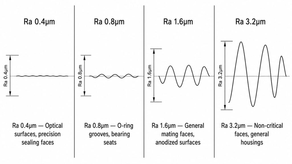
CNC machining produces surface finish in the range of Ra 0.8 to Ra 3.2μm off the machine, depending on tooling, feed rate, and material. The values below are achievable at EPOC CRAFTER under standard production conditions.
| Ra Value | Appearance | Typical Application |
| Ra 0.4μm | Mirror-like, requires hand finishing or fine grinding | Optical surfaces, precision sealing faces, gauge blocks |
| Ra 0.8μm | Smooth, light tool marks barely visible | O-ring grooves, bearing seats, hydraulic sealing faces |
| Ra 1.6μm | Standard finish, fine tool marks visible under light | General precision mating faces, anodized surfaces |
| Ra 3.2μm | Standard machined finish | Non-critical faces, internal pockets, general housings |
| Ra 6.3μm | Visible tool marks | Rough passes, surfaces that will be welded or bonded |
Default finish at EPOC CRAFTER: Ra 1.6μm on functional faces, Ra 3.2μm on non-functional faces, unless otherwise specified on the drawing.
Post-processing effect on Ra: Bead blasting moves Ra from 1.6 to 3.2μm with a texture change (not necessarily smoother). Anodize Type II does not significantly change Ra. Hard anodize (Type III) can increase Ra by 0.2 to 0.4μm due to coating build-up. Electropolishing on stainless reduces Ra by approximately 50 percent.
GD&T and Drawing Requirements
Parts submitted without explicit tolerance callouts are machined to ISO 2768-m. Parts with GD&T callouts per ASME Y14.5-2018 or ISO 1101 are machined and inspected to those callouts directly.
The most common GD&T callouts on prototype parts at EPOC CRAFTER:
Flatness: Applied to sealing faces and reference datums. A flatness callout of 0.02mm on a gasket face means the entire face must fall within a 0.02mm tolerance zone. No single point can deviate beyond that band.
Cylindricity: Applied to bearing bores and precision shafts. Controls roundness, straightness, and taper simultaneously in one callout.
True position: Applied to hole patterns, bolt circles, and mating hole arrays. Defines the allowable deviation of a hole center from its theoretically exact position. A true position of Ø0.1mm at MMC on a bolt circle controls both location and size simultaneously.
Perpendicularity: Applied to bosses, dowel pin holes, and press-fit features. A perpendicularity callout of 0.02mm on a dowel bore means the bore axis cannot deviate more than 0.02mm from the datum plane across the full depth of the bore.
Inspection Methods
| Method | Capability | Used When |
| Hand metrology (calipers, micrometers, bore gauges) | ±0.005mm | Standard prototype inspection, features accessible by hand tools |
| CMM (Coordinate Measuring Machine) | ±0.002mm | GD&T callouts, true position, flatness, multi-feature relationships |
| Laser scanning | 0.02–0.05mm point accuracy | Complex freeform surfaces, full-part dimensional mapping |
| Pin gauges and go/no-go gauges | Fixed size verification | High-volume inspection of critical hole diameters |
Engineering note: If your drawing has GD&T callouts and you need a First Article Inspection (FAI) report, state that explicitly in the order notes. CMM inspection is not run by default on every prototype order. Specify it, and specify which features need CMM measurement, to avoid inspection gaps on critical dimensions.
6. Lead Time and Cost Drivers
Lead time and cost on a CNC prototype order are not fixed numbers. Both are outputs of the same set of variables. Understanding what drives each one lets you adjust the design or the order spec before quoting, not after receiving a price that does not fit the budget or a delivery date that misses the review cycle.
Lead Time
Standard lead time at EPOC CRAFTER for CNC prototype orders:
| Order Type | Quantity | Standard Lead Time | Expedited Lead Time |
| Simple parts (3-axis, 1–2 setups) | 1–5 pcs | 3–5 business days | 1–2 business days |
| Moderate complexity (3–4 setups, standard tolerances) | 1–5 pcs | 5–7 business days | 3–4 business days |
| Complex parts (5-axis, tight tolerances, multiple ops) | 1–5 pcs | 7–10 business days | 5–7 business days |
| Low-volume batch | 10–50 pcs | 10–15 business days | 7–10 business days |
| Low-volume batch | 50–500 pcs | 15–25 business days | 12–18 business days |
What adds lead time
Post-processing adds 1 to 5 business days depending on the process. Anodize Type II adds 2 to 3 days. Hard anodize adds 3 to 5 days. Passivation adds 1 to 2 days. CMM inspection with a full FAI report adds 1 to 2 days on top of machining.
Material procurement adds lead time when the required grade or stock size is not in inventory. Al 6061-T6 and SS 304/316L are stocked. Ti-6Al-4V, SS 17-4 PH, and PEEK require procurement lead time of 3 to 7 business days before machining begins. Confirm material availability at the quoting stage.
Tight tolerances on multiple features extend cycle time per part and require intermediate inspection steps between operations. A part with five features called out at ±0.005mm takes longer to machine and inspect than a part with one.
Cost Drivers
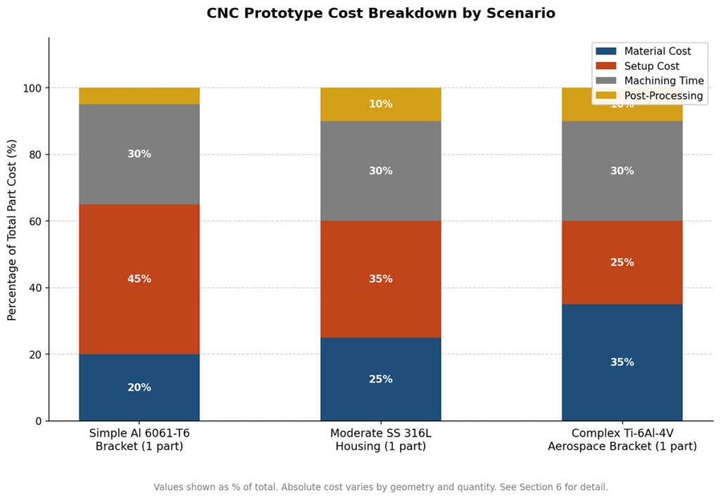
CNC prototype cost breaks into four components: material cost, setup cost, machining time, and post-processing cost. Of these, setup cost and machining time are the two levers most directly controlled by design decisions.
Material cost scales with stock weight removed, not final part weight. A part machined from a 200mm × 150mm × 80mm block of Al 7075-T6 that ends up weighing 300g still carries the cost of the full billet. Designs with very high material removal ratios (above 90 percent) cost more per gram of finished part than near-net-shape designs.
Setup cost is fixed per setup, not per part. A part requiring four setups on a 3-axis machine costs the same setup fee as four separate parts, each requiring one setup. Consolidating features into fewer setups through 5-axis machining or design simplification cuts this cost directly. At quantities of 1 to 3 parts, setup cost frequently exceeds machining time cost.
Machining time scales with material hardness, depth of cut, feed rate, and total volume removed. Al 6061-T6 machines roughly 3 to 4 times faster than SS 316L at equivalent material removal rates, and approximately 6 to 8 times faster than Ti-6Al-4V. On a complex part, material choice alone can shift machining cost by a factor of 3.Post-processing cost is additive and often underestimated at the design stage. Hard anodize on a complex aluminum part with multiple masked features costs more than hard anodize on a simple plate. Every masked feature requires manual preparation time before the anodize bath.
Cost Reduction Without Redesigning the Part
Several adjustments reduce cost without changing the part geometry or function:
Relax tolerances on non-critical features. Every feature tighter than ±0.05mm requires either a dedicated inspection step or a finish pass. Audit the drawing before submitting. If a clearance hole is called out at ±0.01mm and it only needs to clear an M5 bolt, change it to ±0.1mm.
Remove cosmetic surface finish requirements from non-visible faces. Ra 0.8μm on an internal pocket that will never be seen or touched adds a finish pass and inspection time with no functional return.
Consolidate the order. At 1 part, setup cost is 100 percent attributed to that part. At 5 identical parts, setup cost is spread across all five. Unit cost at 5 parts is typically 30 to 50 percent lower than at 1 part on simple geometries.
Choose a stocked material. Switching from Ti-6Al-4V to Al 7075-T6 for a load validation prototype that does not need titanium’s corrosion resistance cuts material cost and lead time simultaneously.
Avoid deep cavities with small-diameter tools. A 3mm end mill cutting a 20mm deep pocket requires slow feed rates, multiple passes, and high tool wear risk. If the cavity depth-to-diameter ratio exceeds 4:1, expect a cost premium. Redesign to a shallower pocket or open the geometry if function allows.
Cost at Low-Volume Scale
Unit cost behavior changes as quantity increases. The table below shows approximate relative cost index (1 part = 100) for a moderate-complexity aluminum housing across quantity breaks
| Quantity | Relative Unit Cost Index | Driver |
| 1 part | 100 | Full setup cost on one part |
| 3 parts | 68 | Setup cost spread across 3 |
| 5 parts | 55 | Setup cost further diluted |
| 10 parts | 42 | Program optimization justified |
| 25 parts | 33 | Dedicated fixturing considered |
| 50 parts | 27 | Fixture amortized, cycle time optimized |
| 100 parts | 22 | Batch scheduling, material bulk buy |
| 500 parts | 16 | Production machining territory |
Engineering note: The steepest unit cost drop happens between 1 and 10 parts. If the prototype review is likely to result in a repeat order within 30 days, ordering 3 to 5 parts on the first run rather than 1 cuts per-part cost substantially and provides spares for destructive testing or parallel validation tracks.
7. DFM Rules for CNC Prototypes
DFM failures on CNC prototype orders fall into two categories: features that cannot be machined as drawn, and features that can be machined but cost far more than necessary. Both types show up at the quoting stage. Catching them before submitting the file saves a round of revision, a delayed quote, and in some cases a scrapped first article.
For a focused analysis of each failure mode with real-order examples, see CNC Prototype DFM Mistakes: 10 Issues That Delay Parts and Inflate Costs.
The ten rules below cover the most common issues seen on prototype submissions at EPOC CRAFTER.
Rule 1: Minimum Wall Thickness
Metal: 0.5mm absolute minimum. Below 1.0mm, expect vibration during machining, deflection under cutting forces, and dimensional variation across the wall. For walls between 0.5mm and 1.0mm, design in support geometry where possible and expect a cost premium.
Engineering plastic (Delrin, PEEK, Nylon): 1.0mm minimum. Plastics deflect more than metals under cutting load. At 1.0mm wall thickness in PEEK, chatter marks and dimensional drift are common without specialized fixturing.
Rule of thumb: Wall thickness should be at least 3 times the end mill diameter used to cut the adjacent pocket. A 2mm end mill cutting a pocket next to a 1mm wall will deflect that wall.
Rule 2: Cavity Depth-to-Width Ratio
Maximum recommended depth-to-width ratio for milled pockets: 4:1. A 4mm wide pocket should not exceed 16mm depth with a standard end mill.
Beyond 4:1, tool deflection increases, chip evacuation becomes difficult, and surface finish degrades on the cavity walls. Beyond 6:1, expect either a specialty long-reach tool with cost premium, or a redesign request.
Practical fix: Where function requires a deep narrow cavity, split the feature into two opposing pockets machined from opposite faces, or add a radius at the base to allow a larger tool diameter.
Rule 3: Internal Corner Radii
All internal corners in milled pockets require a radius. A square internal corner is not machinable with a standard end mill.
Minimum internal corner radius: 1mm for most work. The radius must be equal to or larger than the radius of the tool cutting the pocket.
Recommended practice: Set internal corner radii to at least 1.5 times the pocket depth divided by 4. For a 12mm deep pocket, use a minimum 3mm corner radius. This allows a 6mm diameter end mill, which has better rigidity than a 2mm tool at that depth.
Clearance note: If the part will mate with another component at the internal corner, add a relief groove or undercut to clear the mating part’s external radius rather than calling out a 0.1mm internal corner radius that requires a specialty tool.
Rule 4: Hole Depth-to-Diameter Ratio
Standard drilled holes: Depth up to 3× diameter with standard drills. Up to 10× diameter with deep-hole drilling at cost premium.
Tapped holes: Thread engagement of 1× to 1.5× diameter in aluminum, 1× diameter in stainless steel, is sufficient for prototype load conditions. Deeper tapped holes add cost without meaningful strength gain in most prototype applications.
Blind vs. through holes: Through holes are faster to drill and easier to deburr. Specify blind holes only when the design requires it. A blind hole with a flat bottom requires an end mill operation after drilling, adding time and cost.
Rule 5: Thread Specifications
Use standard thread sizes. Non-standard thread pitches require custom tooling procurement, which adds lead time and cost.
Preferred metric threads for prototype work: M2, M2.5, M3, M4, M5, M6, M8, M10, M12 at standard pitch (per ISO 68-1).
Preferred unified threads: UNC and UNF series per ASME B1.1.
Avoid: Fine-pitch threads in soft aluminum on prototype parts. An M6×0.5 fine pitch thread in Al 6061-T6 strips under torque levels that an M6×1.0 standard pitch handles without issue. Use fine pitch only where axial adjustment or vibration resistance requires it.
Minimum thread depth: 1.5× nominal diameter for metric threads in aluminum. 1× nominal diameter in steel. Shallower than this and the thread will strip before the fastener yields.
Rule 6: Undercuts
Standard end mills cannot reach undercut geometry. Three options exist:
T-slot cutters reach simple rectangular undercuts. Standard T-slot widths are 3mm, 4mm, 5mm, 6mm, and 8mm. Specify the undercut width to match a standard T-slot size.
Lollipop (spherical) cutters reach curved undercuts and dovetail profiles. Available in limited diameters; confirm availability at quoting stage.
5-axis repositioning can reach many apparent undercuts by rotating the part to expose the feature to a standard end mill. This is the cleanest solution for complex geometries but requires 5-axis capability and adds setup time.
If none of the above apply: Split the part into two pieces, machine separately, and join by fastener, press fit, or adhesive bond.
Rule 7: Datum and Fixturing Reference
Every part needs at least one flat reference face and two locating features for fixturing. Parts without a clear datum strategy require custom fixtures, which adds cost and lead time on prototype orders.
Design in at least one face that is: flat to within 0.1mm across its full extent, large enough to clamp without distortion, and free of features that interfere with a vise or clamp.
Avoid: Fully radiused outer profiles with no flat face. A round part with no flats requires a custom soft jaw, which is a fixturing cost added to the first prototype order.
Rule 8: Tolerances on Post-Processed Features
Features that will be anodized, hard-coated, or plated must account for coating build-up in the machined dimension.
Anodize Type II build-up: 0.005 to 0.015mm per surface (total 0.010 to 0.030mm on a diameter).
Hard anodize (Type III) build-up: 0.012 to 0.025mm per surface (total 0.025 to 0.050mm on a diameter).Electropolishing material removal: 0.005 to 0.020mm per surface.
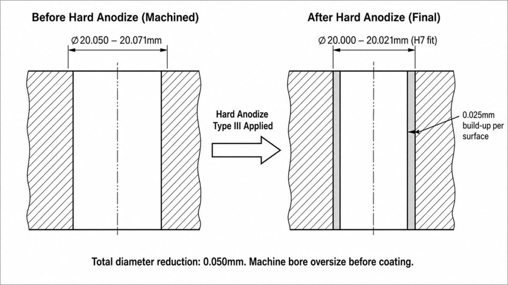
A bore called out at Ø20.000 to Ø20.021mm (H7 fit) after hard anodizing must be machined to Ø20.050 to Ø20.071mm before coating to hit the final dimension. Miss this adjustment and the bore will be undersize after anodizing, requiring a recut or a scrap part.
Rule 9: Text and Markings
Engraved text on CNC parts is machinable. Embossed text requires material to be left standing, which limits tool access and increases machining time.
Minimum engraved text height: 2.5mm for standard V-bit engraving. Below 2mm, character legibility degrades on aluminum. Below 1.5mm, do not specify engraving.
Preferred: Engraved text, 3mm height minimum, 0.3mm depth minimum, located on a flat face with clear cutter access.
Avoid: Text located on a curved or angled face without a flat reference. Text positioned inside a pocket where tool access is restricted.
Rule 10: File Format and Drawing Requirements
Accepted 3D file formats: STEP (.stp, .step), IGES (.igs), Parasolid (.x_t), SolidWorks (.sldprt). STEP is preferred. It carries solid geometry accurately across all CAM systems.
2D drawing requirements: PDF with tolerance callouts, surface finish symbols, GD&T annotations per ASME Y14.5-2018 or ISO 1101, material specification, and finish specification. A 3D file without a 2D drawing is acceptable for simple parts machined to ISO 2768-m. For any part with GD&T callouts or post-processing requirements, a 2D drawing is required.
Avoid: Sending DXF only. DXF carries 2D geometry without solid model data. CAM programming from DXF alone introduces interpretation errors on complex parts.
DFM Checklist
Downloadable PDF: “CNC Prototype DFM Checklist” 10-point checklist matching the rules above, formatted for print. Each rule has a checkbox, a pass/fail criterion, and a field for drawing reference. Available at CNC Prototype DFM Checklist.
Engineers who want to see how these DFM rules apply to real prototype failures can read CNC Prototype DFM Mistakes
| # | Check | Pass Criterion |
| 1 | Minimum wall thickness | Metal ≥ 0.5mm, plastic ≥ 1.0mm |
| 2 | Cavity depth-to-width ratio | ≤ 4:1 for standard tooling |
| 3 | Internal corner radii | ≥ 1mm, match or exceed tool radius |
| 4 | Hole depth-to-diameter ratio | ≤ 3× for standard drills |
| 5 | Thread specifications | Standard metric or unified series |
| 6 | Undercut geometry | T-slot, lollipop, or 5-axis accessible |
| 7 | Datum and fixturing reference | One flat face ≥ clamping area |
| 8 | Post-processing dimensional allowance | Coating build-up accounted for |
| 9 | Text and markings | ≥ 2.5mm height, flat face location |
| 10 | File format | STEP + PDF drawing with full callouts |
8. From Prototype to Low-Volume Production
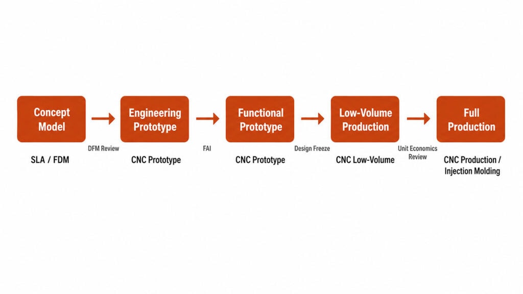
The transition from prototype to low-volume production is not a single decision point. It is a sequence of three questions: is the design frozen, is the process validated, and does the unit economics justify the switch. Getting the sequence wrong costs more than staying in prototype mode longer than necessary.
For the full decision framework covering fixture strategy, batch economics, and crossover thresholds, see From Prototype to Low-Volume Production: When and How to Make the Switch.
Stage 1: Design Freeze
A prototype order is still exploratory. A low-volume production order assumes the drawing is correct, the tolerances are achievable, and the material is final. Placing a 100-part order on a drawing that has not been through at least one full functional test cycle is a common and expensive mistake.
Indicators that design is not yet frozen:
- No first-article inspection (FAI) has been completed and accepted
- Tolerance callouts have not been verified against actual assembly fit
- Material has not been tested in the target environment (temperature, chemical exposure, load)
- Post-processing specification has not been confirmed against functional requirements
Minimum before moving to low-volume production: At least one prototype batch with a completed FAI report, confirmed fit in the assembly, and sign-off from the engineering team on the drawing revision.
Stage 2: Process Validation
A prototype machined in a single setup on a 5-axis machine may not be the most economical route for 200 parts. At low-volume scale, the process route is re-evaluated for repeatability and cost.
What changes between prototype and low-volume production:
| Parameter | Prototype (1–5 parts) | Low-Volume Production (50–500 parts) |
| Fixturing | Soft jaws or vise, adjusted per part | Dedicated fixture, set once per batch |
| Setup frequency | Every part or every 2–3 parts | Once per batch |
| Program optimization | Standard toolpaths | Optimized toolpaths, reduced air cuts |
| Inspection | Per-part, full dimensional | First article + sampling per batch |
| Material procurement | From stock, small quantity | Bulk order, cost reduction on material |
| Surface finish | Per drawing, no batch optimization | Batch processing for post-processing ops |
Typical unit cost reduction from prototype to low-volume production: 25 to 45 percent on simple to moderate complexity parts. Complex parts with tight tolerances see smaller reductions because setup and inspection costs remain high regardless of quantity.
Stage 3: Unit Economics Crossover Points
| Quantity | Recommended Approach | Rationale |
| 1–5 parts | CNC prototype, no dedicated fixture | Setup cost amortized across too few parts to justify fixture investment |
| 5–25 parts | CNC with soft jaw optimization | Program retained from prototype run, minor toolpath optimization |
| 25–100 parts | CNC with dedicated fixture | Fixture cost amortized, cycle time reduction justifies investment |
| 100–500 parts | CNC low-volume production, batch scheduling | Material bulk buy, batch post-processing, scheduling efficiency |
| 500–2,000 parts | CNC production or injection molding evaluation | Injection molding tooling cost begins to amortize at this range for thermoplastics |
| 2,000+ parts | Injection molding (thermoplastic) or production CNC (metal) | Per-part cost crossover favors injection molding for plastics |
Engineering note: These thresholds shift with part complexity and material. A simple aluminum plate reaches the injection molding crossover at a lower quantity than a complex stainless housing. A titanium aerospace bracket never reaches the injection molding crossover because titanium is not injection moldable.
What to Prepare Before Placing a Low-Volume Production Order
Drawing package:
- Final released drawing with revision number
- All tolerances verified against prototype FAI data
- Material and finish specification confirmed
- GD&T callouts reviewed against inspection capability
Reference data from prototype run:
- FAI report from prototype batch
- Any deviation notes or drawing updates made after prototype inspection
- Assembly fit confirmation data
Order information:
- Confirmed quantity and delivery schedule
- Packaging requirements (individual bags, protective foam, bulk)
- Inspection requirements (full FAI on first article of production run, AQL sampling plan for batch)
- Certification requirements (material certs, CoC, PPAP if applicable)
Bridge Production: The Gap Between Prototype and Full Production
Bridge production covers the quantity range where the design is functionally validated but full production tooling is not yet justified. For CNC-machined metal parts, bridge production at EPOC CRAFTER typically runs from 25 to 500 parts per batch, with dedicated fixturing, batch post-processing, and sampling inspection.
Bridge production is the right call when:
- Product launch is imminent but full production tooling lead time is too long
- Market demand is uncertain and full tooling investment carries financial risk
- The part is metal and injection molding is not the production process
- Design changes are still possible and locking into production tooling is premature
Bridge production is not the right call when:
- The design is frozen, volume is confirmed above 2,000 parts per year, and the part is a thermoplastic that can be injection molded
- The per-part cost delta between bridge CNC and production injection molding is large enough to affect product margins materially
The decision criteria and unit economics for each quantity break are covered in detail in From Prototype to Low-Volume Production. Engineers planning a transition from prototype to low-volume production can review EPOC CRAFTER’s low-volume production capabilities and request a batch quote directly through the quoting page.
9. How to Prepare and Submit Your Files
A complete file submission gets a quote back faster and reduces the risk of a part being machined to the wrong spec. Incomplete submissions are the most common cause of quote delays and first-article failures on prototype orders.
What to Submit
Minimum required for a quote: A STEP file of the 3D model. This covers simple parts with no tight tolerances, no GD&T callouts, and no post-processing requirements. Parts will be machined to ISO 2768-m general tolerance and Ra 3.2μm default finish.
Required for production-intent prototype orders: A STEP file plus a 2D drawing in PDF format. The drawing must include:
| Drawing Element | Requirement |
| Title block | Part name, part number, revision, material specification, finish specification, drawing standard (ASME Y14.5-2018 or ISO 1101) |
| Tolerance callouts | All features requiring tighter than ISO 2768-m called out explicitly with ±mm or IT grade |
| GD&T annotations | Flatness, cylindricity, true position, perpendicularity per ASME Y14.5-2018 or ISO 1101 |
| Surface finish symbols | Ra value on all functional faces, default finish noted in title block |
| Thread callouts | Standard designation (M6×1.0-6H, UNC 1/4-20-2B), depth, and whether blind or through |
| Post-processing notes | Anodize type and class, passivation spec, masking requirements for coated features |
| Datum references | At least three mutually perpendicular datum planes identified and labeled |
File Preparation Checklist
3D model:
- Solid model, no surface model or mesh file
- All features fully resolved, no open geometry or missing faces
- Units confirmed (mm preferred, inches accepted)
- File saved as STEP AP214 or AP203
2D drawing:
- All views sufficient to fully define the part geometry
- No conflicting dimensions between drawing views
- Tolerances consistent with manufacturing capability (no ±0.001mm callouts on features that do not require it)
- Material called out by full designation: “Aluminum 6061-T6 per ASTM B209” not just “aluminum”
- Finish called out specifically: “Anodize Type II, Class 2, per MIL-A-8625” not just “anodize”
Multiple parts in one assembly:
- Submit each part as a separate STEP file
- Include an assembly STEP file showing the relationship between parts
- Number each part file to match the drawing part number
Common Submission Errors That Delay Quotes
Sending DXF only. DXF is a 2D format. Without a 3D model, the shop must interpret all depth dimensions from drawing views alone. Interpretation errors are common on complex parts. Always include a STEP file.
Material listed as “stainless steel” with no grade. SS 303, SS 304, and SS 316L have different cost, lead time, and corrosion performance. An unspecified stainless order will be quoted at SS 304 by default. If the part requires 316L, specify it.
Tolerances tighter than the process can hold. A tolerance of ±0.001mm on a 50mm bore is below the capability of standard CNC machining without grinding. Submitting drawings with unrealistic tolerances triggers a DFM review flag and delays the quote while the tolerance is clarified.
No masking instructions on anodized parts with press-fit or threaded features. Anodize build-up in a threaded hole will cause the fastener to seize. Anodize build-up in a press-fit bore will change the interference. Mask these features or call out post-machine thread chase on the drawing.
Sending native CAD files only (SolidWorks .sldprt, CATIA .CATPart). Native files require the receiving shop to have the same CAD software version. STEP is software-agnostic and is the only format that guarantees geometry transfer without version dependency.
Quoting and Order Process at EPOC CRAFTER
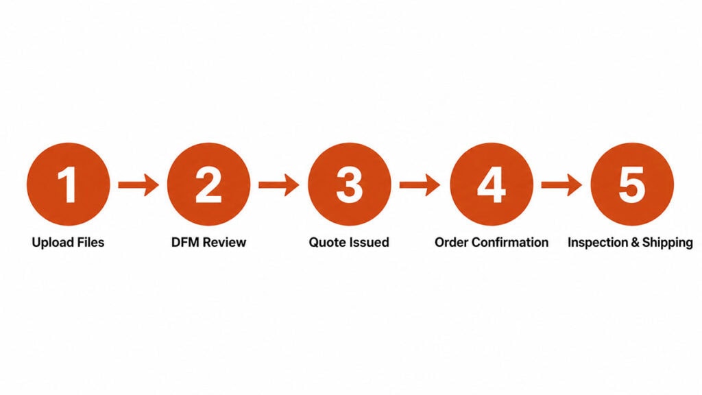
Step 1: Upload files Submit STEP file and PDF drawing through the quote request page. Include quantity, required lead time, and any special inspection or certification requirements in the notes field.
Step 2: DFM review EPOC CRAFTER reviews the submission for manufacturability before issuing a quote. If DFM issues are found, a written DFM report is returned with specific feature callouts and recommended modifications. No charge for DFM review.
Step 3: Quote issued Quote covers per-part price, setup cost, post-processing cost, lead time, and any material procurement lead time if the specified material is not in stock. Quote validity: 30 days.
Step 4: Order confirmation Confirm the order with purchase order or written approval. Production begins after order confirmation and drawing sign-off.
Step 5: Inspection and shipping Parts are inspected per the drawing before shipping. FAI report included if specified in the order. Certificate of Conformance (CoC) available on request. Material certifications available on request for all stocked materials.
Engineers ready to submit files can go directly to the quote request page. For material certification requirements on aerospace or medical prototype orders, the capabilities overview at CNC machining covers certification and inspection options in detail.
10. Frequently Asked Questions
Q1: How much does a CNC prototype cost?
CNC prototype cost depends on material, geometry complexity, number of setups, tolerances, and post-processing. A simple aluminum bracket machined from Al 6061-T6 in one or two setups runs USD 80 to 200 per part at quantity 1. A moderate-complexity stainless housing with four setups and anodize finish runs USD 300 to 600 per part. A complex titanium aerospace bracket with tight GD&T callouts and CMM inspection runs USD 500 to 1,500 per part. The steepest cost driver is setup count, not machining time. Reducing setups through design consolidation or 5-axis machining cuts cost more than any other single change. At quantity 5, unit cost drops 40 to 50 percent compared to quantity 1 on simple geometries.
Q2: How long does CNC prototype machining take?
Standard lead time at EPOC CRAFTER is 3 to 5 business days for simple parts at quantity 1 to 5, and 7 to 10 business days for complex parts with multiple setups and tight tolerances. Post-processing adds 1 to 5 business days depending on the process: anodize Type II adds 2 to 3 days, hard anodize adds 3 to 5 days, passivation adds 1 to 2 days. Material procurement adds 3 to 7 business days for non-stocked grades such as Ti-6Al-4V, SS 17-4 PH, and PEEK. Expedited lead time is available on most orders: simple parts can be delivered in 1 to 2 business days. State the required delivery date at the quoting stage so material availability and scheduling can be confirmed before order placement.
Q3: What tolerances can CNC machining hold for prototypes?
Standard commercial CNC machining holds ±0.01mm on general features. Precision features with dedicated fixturing and finish passes reach ±0.005mm. Features without explicit callouts are machined to ISO 2768-m (medium grade), which covers ±0.1mm on dimensions up to 30mm and ±0.15mm on dimensions from 30 to 120mm. For GD&T callouts, flatness to 0.02mm, true position to Ø0.05mm, and cylindricity to 0.01mm are achievable on prototype parts with proper datum setup. Calling out tight tolerances on every feature adds cost without functional benefit. Specify ±0.005mm only on features that mate, seal, or locate against another component.
Q4: What is the best material for a CNC prototype?
Al 6061-T6 covers most general prototype requirements: good strength, excellent machinability, compatible with anodizing, and low cost relative to steel or titanium. Move to Al 7075-T6 when tensile strength above 310 MPa is required. Use SS 316L for corrosion-resistant or medical applications. Use Ti-6Al-4V when weight-to-strength ratio is the primary constraint or when the prototype will go directly into regulatory testing. For engineering plastic prototypes, Delrin machines cleanly and covers most mechanical applications below 90°C. Use PEEK only when the application genuinely requires operation above 150°C or exposure to aggressive chemicals. Selecting an unnecessarily high-performance material on a prototype that only needs dimensional validation adds cost and lead time with no engineering return.
Q5: CNC machining vs. 3D printing: which is better for prototyping?
CNC machining is better when the part requires functional testing in production-equivalent material, tolerances tighter than ±0.1mm, or surface finish below Ra 3.2μm. 3D printing is better for concept models, organic geometries with no flat reference datums, internal lattice structures, and situations where getting a physical shape in hand within 24 hours matters more than material accuracy. The two processes are not in direct competition for most prototype programs: SLA or FDM covers early concept iterations, CNC covers engineering validation and functional testing. DMLS is the exception, covering metal geometries that cannot be machined, at higher cost and longer lead time than CNC for equivalent simple geometries.
Q6: What is the minimum order quantity for CNC prototype machining?
One part. There is no minimum order quantity for CNC prototype machining at EPOC CRAFTER. Setup cost on a single part is fully attributed to that part, which is why unit cost at quantity 1 is the highest point on the cost curve. Ordering 3 to 5 parts instead of 1, where the design allows, cuts unit cost by 40 to 55 percent and provides spares for parallel testing or destructive evaluation. For low-volume production orders, dedicated fixturing becomes cost-justified at quantities above 25 parts per batch.
Q7: What file format do I need for CNC prototype machining?
STEP format (.stp or .step) is the preferred 3D file format. STEP transfers solid geometry accurately across all CAM systems without software version dependency. IGES, Parasolid (.x_t), and SolidWorks (.sldprt) are also accepted. For any part with tolerance callouts, GD&T annotations, or post-processing requirements, a 2D drawing in PDF format is required alongside the 3D model. The drawing must include material specification by full grade designation, surface finish callouts in Ra values, tolerance callouts on all critical features, and post-processing notes with masking instructions where applicable. DXF files alone are not sufficient for complex parts.
Q8: Can CNC machining produce production-equivalent prototypes?
Yes, when the production process is also CNC machining. A CNC prototype machined from the same material grade, to the same tolerances, with the same post-processing as the production part is production-equivalent by definition. It validates the drawing, the process capability, and the material behavior in a single step. Where the production process differs (injection molding, casting, forging), the CNC prototype approximates the production part’s geometry and material but does not replicate the grain structure, residual stress, or surface condition of the production process. In those cases, the CNC prototype serves as a functional geometry check, not a full production-equivalent test article.
CNC machining covers the full range from first-article validation to bridge production. The process delivers tolerances to ±0.005mm, surface finishes from Ra 0.8μm, and no tooling cost at quantities from 1 to 500 parts. It is not the right process for every prototype: organic geometries, internal lattice structures, and pure concept models belong on additive processes. For any part that will be load-tested, pressure-cycled, or installed into a mating assembly, CNC in the production material is the lowest-risk path to a validated design.
Three conditions determine whether a CNC prototype order will go smoothly: the drawing is complete with explicit tolerance and finish callouts, the material is specified by full grade designation, and DFM rules on wall thickness, corner radii, and cavity depth are met before the file is submitted. Most first-article failures trace back to one of these three gaps, not to the machining process itself.
For orders at EPOC CRAFTER, submit a STEP file and PDF drawing through the quote page. DFM review is included at no charge. Standard lead time is 3 to 7 business days depending on complexity.
Ready to Quote Your CNC Prototype?
Upload your STEP file and get a DFM review + quote within 12 hours. No tooling cost. Minimum 1 part.
