

Dewey Wu General Manager & senior mechanical engineer at EPOC CRAFTER, 15 years in design engineering, quality, and metallurgy. Hands-on across CNC machining, metalwork, sheet metal, and prototyping (subtractive + 3D printing).
A surface roughness chart is a reference that pairs each Ra value with its RMS equivalent, its ISO N grade, and the machining process that reaches it, across standard values from Ra 0.025 µm (N1) to Ra 50 µm (N12). Reading it correctly changes what you pay. A milled face at Ra 3.2 µm comes off the tool in one pass, while Ra 0.4 µm on the same face needs a separate grinding setup.
This guide gives you three things: the conversion values you came to look up, what each CNC process delivers as-machined on 6061-T6, 7075-T6, 304, 316, POM, and PA6, and how a single Ra callout is accepted under the ISO 21920 maximum rule that replaced ISO 4287 in 2021. Three moves decide a finish: Read the callout, match it to what each process can Reach, and apply the Rule that accepts the part.
1. Surface roughness chart at a glance
A surface roughness chart lines up the values that name one finish: the ISO N grade, Ra in micrometers, Ra in microinches, and RMS. Ra 3.2 µm, 125 µin, and N8 all describe the same surface, the standard finish off a CNC mill or lathe. RMS reads about 11 percent above Ra.
| N12 | 50 | 2000 | 2220 | Sand casting, flame cutting |
| N11 | 25 | 1000 | 1110 | Rough turning, sawing |
| N10 | 12.5 | 500 | 555 | Heavy milling |
| N9 | 6.3 | 250 | 278 | Rough machining, drilling |
| N8 | 3.2 | 125 | 139 | Standard mill or turn, as-machined |
| N7 | 1.6 | 63 | 70 | Fine milling or turning |
| N6 | 0.8 | 32 | 36 | Precision turning, grinding |
| N5 | 0.4 | 16 | 18 | Grinding |
| N4 | 0.2 | 8 | 8.9 | Fine grinding, honing |
| N3 | 0.1 | 4 | 4.4 | Honing, lapping |
| N2 | 0.05 | 2 | 2.2 | Lapping |
| N1 | 0.025 | 1 | 1.1 | Superfinishing, lapping |
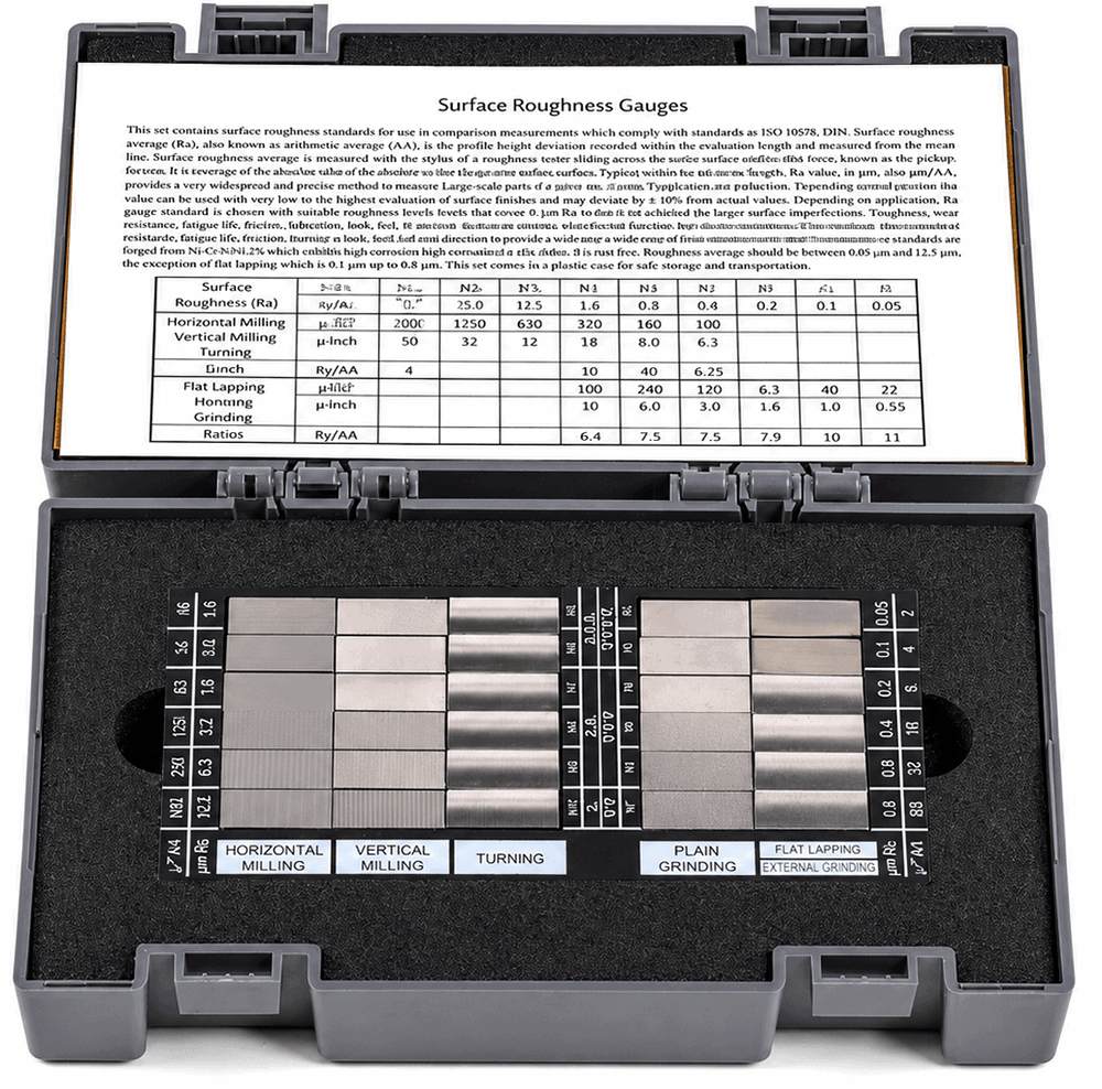
RMS runs about 11 percent above Ra, so RMS ≈ Ra × 1.11 (Machinery’s Handbook, 32nd ed., p.801). RMS is a calibration offset from Ra, not a separate standard. Rz is left out on purpose: Ra and Rz have no fixed conversion, covered in Section 2.
Engineering note. On a non-mating face, N8 (Ra 3.2 µm) beats N7 (Ra 1.6 µm), because N8 comes off the roughing pass while N7 adds a finishing pass and cycle time. The exception is a face that later carries a gasket, seal, or bonded joint, where N7 or finer earns the time. A drawing showing only 125 sets Ra 3.2 µm as a ceiling, not an average, and Section 5 explains why.
These columns tell you what a finish is called, not whether to call for it. That choice sits one level up, in your drawing tolerance decisions, where finish trades against dimensional tolerance on the same feature.
2. Ra vs Rz vs RMS, and why Ra and Rz never convert
Ra reports the average of a surface. Rz reports its extremes. A profilometer reads the same Ra 1.6 µm on two surfaces where one is uniform and the other hides a valley twice as deep, because Ra averages that valley away and Rz does not. The parameter you pick, not just the value, decides whether the part works.
| Ra, arithmetic mean height | Average height deviation over the evaluation length | Overall texture and consistency | Default for most machined surfaces |
| Rz, maximum height | Mean of the largest peak-to-valley heights across the section lengths | One deep scratch or high peak that Ra hides | Sealing faces, fatigue-loaded surfaces |
| Rq / RMS, root mean square height | Same profile as Ra, squared before averaging | Larger peaks and valleys, weighted heavier | Reading older US drawings; runs about 11% above Ra |
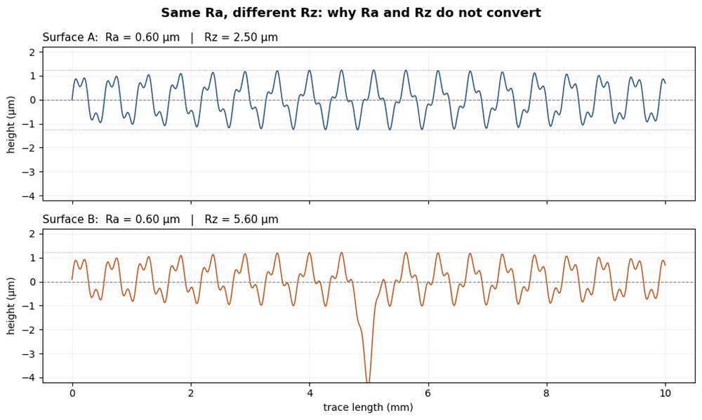
ISO 21920-2:2021 defines Ra and Rz on the same profile but publishes no formula between them. The shop habit of writing Rz around 4 to 7 times Ra is a process-dependent estimate, and the multiplier shifts with the cut. Accepting a part by converting a measured Ra into an Rz, or the reverse, has no basis in the standard and passes parts that should fail.
Engineering note. On an O-ring groove or a dynamic seal, specify Rz, because one valley deeper than the average leaks under pressure even when the Ra reading passes. On a structural bracket face, Ra alone is enough, and an Rz callout there only raises inspection cost. The same split sets finish on a bearing seat, where the fit and the surface work together and both belong on the drawing next to the H7/g6 clearance fit.
3. What each CNC process delivers as-machined
Standard CNC parts come off the mill or lathe at Ra 3.2 µm (N8). Milling and turning reach Ra 1.6 µm and Ra 0.8 µm with a finishing pass and sharp tooling. Below Ra 0.4 µm the part leaves the cutting machine for grinding, honing, or lapping. The table shows the range each process holds, not a value it guarantees.
| Milling | 1.6-12.5 / 63-500 | 0.20 / 8 | Sharp carbide, light finishing pass, rigid setup |
| Turning and boring | 0.80-3.2 / 32-125 | 0.025 / 1 | Fine nose radius, higher speed, no built-up edge |
| Drilling | 3.2-12.5 / 125-500 | 1.6 / 63 | A drill alone stays rough; ream or bore to improve |
| Reaming | 1.6-3.2 / 63-125 | 0.80 / 32 | Self-guiding reamer on long holes |
| Broaching | 1.6-6.3 / 63-250 | 0.80 / 32 | Burnishing pass after the broach |
| EDM | 3.2-12.5 / 125-500 | 1.6 / 63 | Low discharge energy, fine finishing settings |
| Grinding | 0.20-1.6 / 8-63 | 0.025 / 1 | Required for anything below Ra 0.4 off the mill |
| Honing | 0.20-0.80 / 8-32 | 0.025 / 1 | Bore finishing after grinding |
| Lapping | 0.05-0.40 / 2-16 | 0.012 / 0.5 | Final finishing, removes less than 0.13 mm |
Source: Machinery’s Handbook, 32nd ed., Table 1, p.803 (milling reaches Ra 0.20 µm at the less-frequent low end). ASM Handbook Vol.16 (Fig.5) gives comparable process bands. Both call these ranges typical, so treat them as a starting point, not an acceptance limit.
Your finish depends on the material and the feature, so we log Ra by feature: a milled face, a side wall, and a bored hole off the same tool read differently.
According to Dewey Wu, “The chart value assumes a sharp tool. On 6061-T6 we hold Ra 1.6 µm off a single finishing pass, but as that insert wears the same pass drifts rougher from edge buildup, so we index tools on measured finish, not on flank wear alone.”
Feed rate and a sharp edge move a finish most. Built-up edge, where work material welds to the tool, is the main cause of a rough turned surface. It is why a finish that passed last week can fail this week on the same CNC machining program with a worn tool.
4. Why the callout changed in 2021
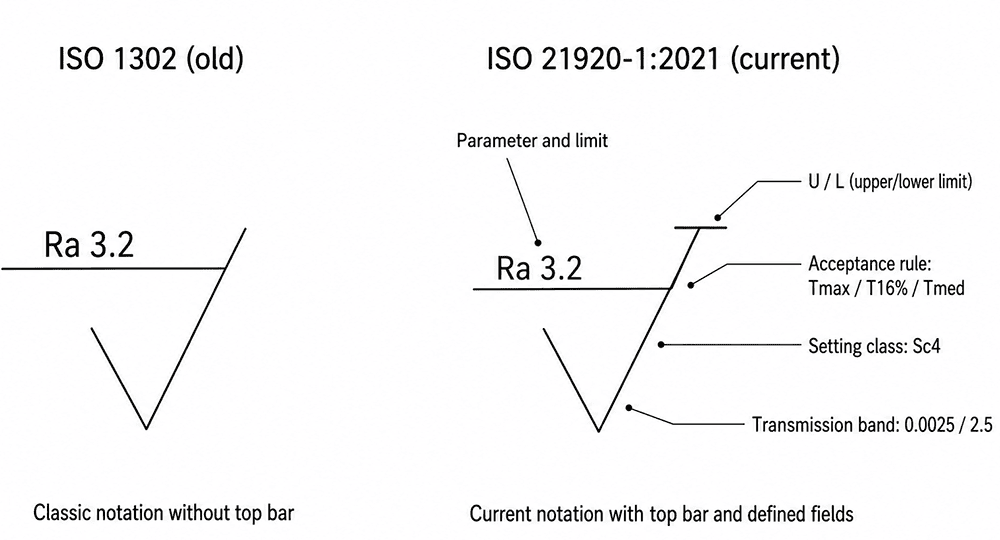
ISO 21920 replaced the old surface texture standards in 2021: ISO 21920-2 cancels ISO 4287, ISO 21920-3 cancels ISO 4288. The number looks the same, but three things moved under it. The symbol now carries a bar across the top that separates it from the old ISO 1302 tick. The old sampling length (lr) is now the section length (lsc). And the cut-off follows from the Ra value you specify.
Under ISO 4288, shops defaulted almost everything to a 0.8 mm cut-off. ISO 21920-3 ties the cut-off to the tolerance through a setting class, so an Ra 3.2 µm surface and an Ra 0.4 µm surface measure over different lengths.
| Sc1 | 0.08 | 0.4 | U ≤ 0.02 |
| Sc2 | 0.25 | 1.25 | 0.02 < U ≤ 0.1 |
| Sc3 | 0.8 | 4 | 0.1 < U ≤ 2 |
| Sc4 | 2.5 | 12.5 | 2 < U ≤ 10 |
| Sc5 | 8 | 40 | U > 10 |
Source: ISO 21920-3:2021, Table 3. Evaluation length is five section lengths. The filter is Gaussian per ISO 16610-21.
An Ra 3.2 µm surface falls in Sc4: default cut-off 2.5 mm over a 12.5 mm evaluation length, not the 0.8 mm many operators still dial in. Ra 1.6 and Ra 0.8 µm fall in Sc3 at 0.8 mm. Measure Ra 3.2 at 0.8 mm and you filter out waviness the drawing meant to catch, and the reading comes back low.
Engineering note. When a drawing gives only Ra 3.2 with no cut-off, apply the Sc4 default of 2.5 mm, not 0.8 mm, because the standard derives the cut-off from the value. The exception is a title block that names ISO 4287 or ISO 4288, where the older defaults govern until reissue. A part fails inspection more from measurement setup than from machining. Where a size is left untoleranced, the default comes from ISO 2768 general tolerances, on a separate track from finish.
5. The acceptance rule nobody reads, maximum not 16 percent
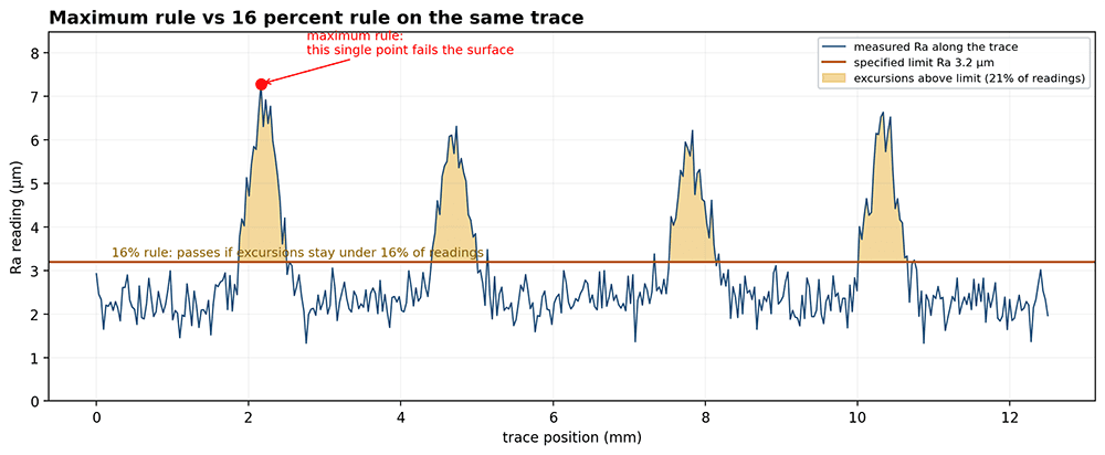
A single roughness limit is now a hard ceiling. ISO 21920 makes the maximum rule the default, so no measured value may exceed it. Write Ra 3.2 and every trace has to come in at or under 3.2 µm. A lone 125 on a print is a maximum, not an average, and not a value allowed to exceed the limit 16 percent of the time.
ISO 4288 used the 16 percent rule, where a surface passed if no more than 16 percent of readings crossed the limit. ISO 21920 demoted it, so a supplier and customer now reach the same verdict: one deep reading fails the surface outright.
| Maximum (default) | Tmax, or no symbol | No measured value exceeds the limit | Where the worst values are expected |
| 16 percent | T16% | Up to 16% of values may exceed the limit | Spread evenly across the surface |
| Median | Tmed | The median value meets the limit | Spread evenly across the surface |
Source: ISO 21920-1:2021 and 21920-3:2021. The maximum rule holds with or without the Tmax symbol. ISO 21920-1 Annex F records why 16 percent lost the default: in most companies it was unknown and unused, and it contradicts a designer treating a limit as a real limit.
The rules also move the probe. Maximum tells the inspector to measure where the worst finish sits: the tool-lift mark, the entry burr, the chatter zone near a corner. The 16 percent rule spreads traces evenly. Different inspection plan, different reject rate.
Engineering note. On a bore that must seal, leave the default and let the maximum rule apply, because it rejects the one bad trace a seal will find anyway. On a cosmetic surface where an occasional deeper mark does no harm, specify T16% to avoid scrapping over one reading. State the rule you want; a drawing that predates 2021 was written under the opposite one.
According to Dewey Wu, “We flag any incoming drawing that carries a single Ra number with no acceptance rule and no standard year. Drawn under ISO 4288 we inspect to 16 percent, under ISO 21920 we inspect to maximum, and the same surface can pass one and fail the other. That one line decides scrap, so we confirm it before the first cut.”
6. How Ra is measured, cut-off and lay direction
A roughness reading repeats only when the cut-off, the evaluation length, and the probe direction are fixed. Change the cut-off and the same surface returns a different Ra. The cut-off comes from the setting class in Section 4, and the probe runs across the lay.
| 0.006 < Ra ≤ 0.02 | 0.08 | 0.4 |
| 0.02 < Ra ≤ 0.1 | 0.25 | 1.25 |
| 0.1 < Ra ≤ 2 | 0.8 | 4 |
| 2 < Ra ≤ 10 | 2.5 | 12.5 |
| 10 < Ra ≤ 80 | 8 | 40 |
Source: Machinery’s Handbook, 32nd ed., Table 3, p.815; it matches the ISO 21920 setting classes and gives a second source for the same defaults. With no cut-off stated on an older ANSI/ASME drawing, 0.8 mm applies (p.807). Under ISO 21920 the cut-off follows the setting class, so Ra 3.2 µm measures at 2.5 mm.
Roughness is read across the lay, the direction that gives the highest value, because a probe running along the tool marks slides down the grooves and reads the surface as smoother than it is. On a turned OD the lay is circumferential, so the probe runs along the axis; on a milled face it crosses the tool path.
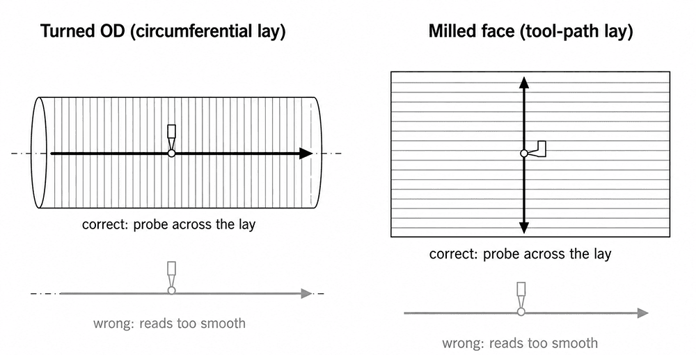
A skidded stylus gauge reads Ra but cannot report waviness or form. A skidless stylus or optical profiler captures the full profile. A contract report needs a skidless instrument with a stated cut-off and traceable calibration, so it holds on re-measure.
Engineering note. When a supplier’s Ra passes and yours fails on the same part, check the cut-off and the lay direction before questioning the machining. A 0.8 mm cut-off on an Ra 3.2 µm surface reads low, and a probe drawn along the lay reads low again, so two setup errors hide a real defect. The exception is a face with no clear lay, such as bead-blasted or cast, where only the cut-off and instrument type matter. A coating sits outside this reading: the shift from [anodizing on machined 6061][URL: /machining-6061-for-anodize/] is measured before and after plating.
7. How to call out surface finish on a drawing, ISO and US
A finish callout needs three parts to be unambiguous: the parameter, the limit value, and the acceptance rule. Under ISO 21920 the minimum callout is the graphical symbol plus the parameter and its limit, such as Ra 3.2. If you stack two parameters, the first line drives the default settings.
ISO 21920-1 fixes what sits at each position.
| Parameter and limit | The parameter symbol, tolerance type, and value | Ra 3.2 or U Ra 3.2 |
| Tolerance limit U or L | Upper or lower limit; upper is the default | U 3.2 / L 0.8 |
| Acceptance rule | Tmax, T16%, or Tmed; maximum applies if none is shown | Tmax |
| Setting class or nesting index | Sets cut-off and evaluation length | Sc4 |
| Transmission band | Short and long wavelength cut-off, with a slash | 0.0025-2.5 |
Source: ISO 21920-1:2021. The bar across the top of the symbol distinguishes it from the old ISO 1302 symbol; a slash separates the specification sections.
US drawings run on a different standard. ASME Y14.36-2018 keeps its own symbol, and the field positions do not match the ISO order, so reading a US print with ISO habits misplaces the values.
| a | Transmission band, the cut-off values |
| b | Parameter designation and limit value, such as Ra 3.2 |
| c | Evaluation length as a number of sample lengths |
| e | Lay symbol |
| f | Material removal modifier |
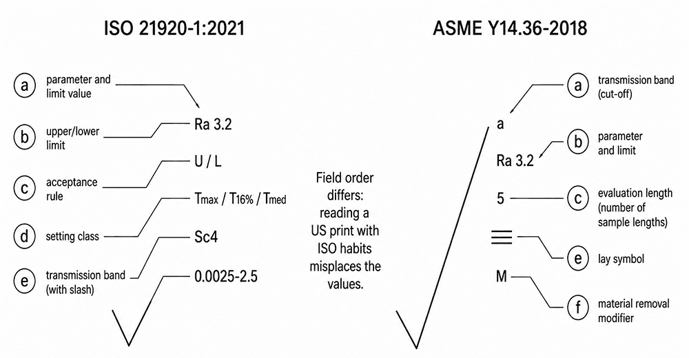
Source: ASME Y14.36-2018, Figure 4-2. A single value is a maximum: the standard’s own Figure 6-1 example treats Ra 3.2 µm as the maximum, any process acceptable. The 2018 revision added all-around and all-over symbols and removed the material removal allowance value the 1996 version carried. Parameters point to ASME B46.1, and the normative reference is ISO 1302, not ISO 21920.
Two things follow. A US drawing to Y14.36-2018 still sits in the ISO 1302 world, while an ISO drawing to 21920-1 uses the newer top-bar symbol, so the same Ra 3.2 face can carry two different-looking callouts. And a single value is a maximum under both, matching Section 5.
Engineering note. When you send a drawing to another region, name the standard in the title block: a bare Ra 3.2 means the ISO 1302 symbol to a US supplier and the ISO 21920 symbol to a European one, and the cut-off defaults differ. State Sc4 or the cut-off directly when the value sits near a setting-class boundary, since a reader who assumes 0.8 mm on Ra 3.2 measures it wrong. Keep the tapped hole surface requirements in the same block when threaded features share the part.
8. Surface finish after coating
A coating changes the surface you measured. Anodizing grows the oxide layer and shifts both the dimension and the Ra; thick plating fills the peaks. The finish on this chart is the as-machined value, before treatment. When a part is anodized or plated, measure Ra before and after and state which the drawing controls, because a callout that ignores the coating accepts the wrong surface. The pre-anodize numbers sit in pre-anodize machining allowances.
9. Frequently asked questions
What is a 125 finish?
A 125 finish is Ra 125 µin, equal to Ra 3.2 µm and ISO grade N8. It is the standard finish off a CNC mill or lathe. Under ISO 21920 a lone 125 is a maximum, so every trace must come in at or under it. It suits brackets, housings, and non-mating faces, but not a dynamic seal or a press fit, which need Ra 1.6 µm or finer.
How is Ra measured?
A stylus or optical profiler traces the surface across the lay, in the direction that gives the highest reading. The cut-off and evaluation length come from the value: an Ra 3.2 µm surface uses a 2.5 mm cut-off over a 12.5 mm evaluation length under ISO 21920. A skidded shop gauge reads Ra only; a skidless profiler captures the full profile for a traceable report.
Does bead blasting change Ra?
Bead blasting raises Ra and replaces directional tool marks with a uniform matte texture. A milled face at Ra 1.6 µm reads rougher after blasting, so treat it as a cosmetic finish, not a controlled Ra target. Blasting removes the lay, so direction stops mattering and only the cut-off and instrument type apply to the reading.
What surface finish do I get as-machined?
As-machined CNC parts come off the tool at Ra 3.2 µm (N8). A finishing pass with sharp tooling reaches Ra 1.6 µm, and precision turning or milling reaches Ra 0.8 µm. Below Ra 0.4 µm the part needs grinding, honing, or lapping. The value shifts with the material and the feature, so a milled side wall and a turned OD off the same job read differently.
Is RMS the same as Ra?
RMS and Ra describe the same profile with different math. RMS squares the height deviations before averaging, so it reads about 11 percent above Ra, near 70 µin RMS at Ra 63 µin. RMS shows up on older US drawings; Ra is the modern default on ISO and ASME prints. Convert with RMS ≈ Ra × 1.11, and do not apply this factor to Rz, which converts to neither.
Can I convert Ra to Rz?
No fixed conversion exists. ISO 21920-2 defines both on the same profile but publishes no formula linking them, and the shop estimate of Rz around 4 to 7 times Ra changes with the process. Converting a measured Ra into an Rz passes surfaces that should fail, because Rz catches a single deep valley that Ra averages away. Specify Rz directly on sealing and fatigue-loaded surfaces; do not derive it.
Why does my supplier’s Ra pass when mine fails?
Two settings explain most gaps: the cut-off and the lay direction. A 0.8 mm cut-off on an Ra 3.2 µm surface reads lower than the correct 2.5 mm cut-off, and a probe drawn along the tool marks reads lower than one drawn across them. Confirm both labs used the same cut-off, evaluation length, and probe direction, and the same acceptance rule, before you question the machining.
10. Related resources
Related Article: How to tolerance a CNC drawing covers the three-layer decision framework (default / explicit ± / GD&T) that decides where an Ra callout belongs on the drawing in the first place.
Related Standards Reference: the ISO 2768 class tables give the default limits for any dimension left untoleranced, on a separate track from finish.
Related Article: ISO 286 fits for bearing seats shows how finish and the fit class work together on a bearing seat or bushing bore.
Related Capability: surface finishing services cover bead blasting, anodizing, and the processes that reach below Ra 0.4 µm.
Related Article: metric thread and tapped hole callouts cover finish on threaded features and where it belongs in the callout.
Confirm the standard and the acceptance rule on every drawing before the first cut, and send us the print for a finish and cost review through our RFQ.
Ready to Quote Your CNC Prototype?
Upload your STEP file and get a DFM review + quote within 12 hours.
No tooling cost. Minimum 1 part.
