

Dewey Wu General Manager & senior mechanical engineer at EPOC CRAFTER, 15 years in design engineering, quality, and metallurgy. Hands-on across CNC machining, metalwork, sheet metal, and prototyping (subtractive + 3D printing).
Sheet metal design guidelines are the engineering rules governing minimum bend radii (≥1× material thickness), hole-to-bend distances (≥2.5t + r), flange lengths (≥4t), and tolerance callouts (per ISO 2768-1:1989 medium class, ±0.1 mm to ±0.5 mm depending on nominal dimension) that determine whether a flat-pattern part can be cut, bent, and formed without rework. Violating one rule at the design stage creates rework at forming, finishing, or both. A 3 mm diameter hole placed 1 mm from a bend line in 1.5 mm 5052-H32 aluminum distorts during press brake forming, forces a secondary deburring pass, and adds 15–20% to per-part cost on a 200-piece run. This guide covers six DFM checkpoints from material selection through surface finish, with values referenced to ISO 2768-1:1989 and EPOC CRAFTER production data, giving you a repeatable audit sequence to close DFM gaps before the drawing reaches the fabrication floor.

1. What Makes Sheet Metal Parts Fail DFM Review
Sheet metal DFM failures cluster in six areas: wrong material-to-bend-radius pairing, features inside the bend deformation zone, missing bend relief, over-tight tolerance callouts, unfavorable grain orientation, and insufficient hardware clearance.
Sheet metal production follows a fixed sequence that constrains every upstream design choice. A blank is cut by laser, waterjet, or CNC punch, then formed on a press brake, then finished with deburring, hardware insertion, and surface treatment. Each stage adds geometric constraints that feed back to the flat-pattern layout. A 4 mm slot that clears all spacing rules on the flat pattern can warp into an hourglass shape after forming if the slot sits within 2.5t + r of the bend centerline, where t is material thickness and r is the inside bend radius.
Six recurring failure areas map to this production sequence in a predictable order. Organizing them into a fixed audit turns ad hoc review into a repeatable process. This guide uses a framework called the Six-Gate DFM Check, where each gate corresponds to one production-stage constraint. You run through the six gates on your flat pattern before sending the drawing out; any gate that flags a violation gets resolved before the next gate is checked.
| 1 | Material and Thickness Selection | Alloy grade, gauge, min. bend radius compatibility |
| 2 | Bend Radius, Relief, and Flange Rules | Min. radius ≥ 1t, relief width ≥ t, flange ≥ 4t |
| 3 | Hole, Slot, and Feature Placement | Hole-to-bend ≥ 2.5t + r, hole-to-edge ≥ 3t, min. diameter ≥ t |
| 4 | Tolerances and Drawing Callouts | ISO 2768-1:1989 medium class, angular tolerance per shorter-side length |
| 5 | Grain Direction and Forming Sequence | Bend axis perpendicular to rolling direction |
| 6 | Surface Finish and Hardware | Coating thickness offset, PEM insert edge clearance |
Gate-by-gate checking catches each failure mode at the lowest-cost point in the production chain. Revising a hole-to-bend violation at the drawing stage costs you one revision cycle of 1–2 days and zero material. Discovering the same violation after press brake setup has started costs scrap blanks, brake re-setup time, and a schedule push. For parts with bends crossing multiple planes in 1.0–2.0 mm aluminum or stainless steel, Gate 5 (grain direction) prevents crack-related scrap that single-plane parts never encounter, because multi-plane bends force at least one bend to run parallel to the rolling direction where elongation drops and fracture risk increases.
EPOC CRAFTER’s sheet metal fabrication team runs a Six-Gate DFM review on every incoming drawing before quoting, flagging violations with specific revision recommendations rather than generic reject notices.
Engineering Note: For a 500-piece run of 1.5 mm 304 stainless steel brackets, a single bend-radius violation discovered after forming adds 2–3 hours of press brake re-setup and generates 5–8% scrap from deformed blanks. The same violation caught during DFM review costs zero material and zero machine time. The cost gap widens at higher volumes: on a 2,000-piece run, post-forming scrap from one uncaught violation can consume the equivalent of 100–160 blanks.
2. The Six-Gate DFM Check for Sheet Metal Parts
The Six-Gate DFM Check is a sequential audit that maps each design decision to the production stage where it creates cost, scrap, or delay if left unresolved. Gates 1 through 3 lock the flat-pattern geometry. Gates 4 through 6 lock the drawing callouts, forming strategy, and post-process specs.
2.1 Gate 1. Material and Thickness Selection
Material grade and sheet thickness set the boundary conditions for every downstream gate. Bend radius limits, achievable tolerances, cutting method, and surface treatment options all derive from the alloy and gauge selected at this stage. Changing material after tooling setup on a 300-piece batch costs a full re-quote, new nesting layout, and press brake re-programming.
Five alloys cover the majority of commercial sheet metal applications at EPOC CRAFTER. The table below lists each alloy with its standard gauge range, yield strength, minimum bend radius multiplier, and application context.
| 5052-H32 Al | 0.8, 1.0, 1.5, 2.0, 3.0 | 193 | ≥ 1t | Enclosures, brackets, HVAC panels |
| 6061-T6 Al | 1.0, 1.5, 2.0, 3.0 | 276 | ≥ 3t | Structural brackets, heatsinks, chassis |
| 304 Stainless | 0.8, 1.0, 1.2, 1.5, 2.0 | 215 | ≥ 1t | Food-grade housings, marine panels |
| 1018 CRS | 1.0, 1.2, 1.5, 2.0, 3.0 | 370 | ≥ 1t | Mounting plates, motor brackets |
| Galvanized Steel | 1.0, 1.2, 1.5, 2.0 | 250–350 (varies) | ≥ 1t | Outdoor enclosures, electrical panels |
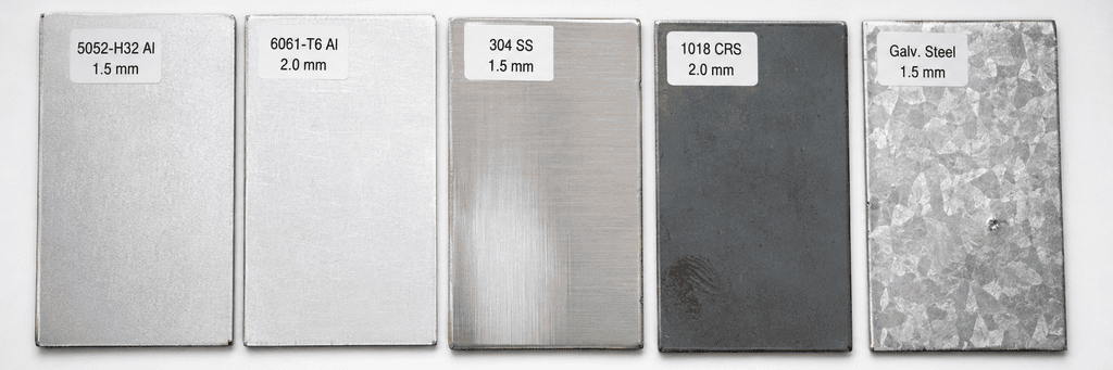
Thinner gauges (0.8–1.0 mm) reduce blank weight and laser cutting time per part but increase springback after bending, demanding tighter press brake control and sometimes a second forming hit. Thicker gauges (2.0–3.0 mm) produce more stable bends with less springback but require higher tonnage press brakes, longer laser pierce times, and wider minimum bend radii on harder alloys.
6061-T6 aluminum requires a minimum bend radius of 3× material thickness to avoid cracking on the outer fiber. Bending 2.0 mm 6061-T6 at 1× thickness (R2.0) produces visible micro-cracks on the tensile surface that propagate under vibration loading. Switching the same geometry to 5052-H32 at R2.0 (1× thickness) produces a clean bend with no cracking, because 5052-H32 elongation at break reaches 12–17% compared with 8–10% for 6061-T6. When your design requires both the structural stiffness of 6061-T6 and tight bend radii below 3t, consider redesigning the bend zone with a wider radius or switching to a two-piece welded assembly.
For a complete property comparison across these five alloys, covering tensile strength, elongation, corrosion resistance, weldability, and gauge-to-millimeter conversion, see the sheet metal materials selection guide in this cluster.
Engineering Note: Galvanized steel adds a zinc coating layer of 7–20 μm per side. When you bend galvanized sheet at radii below 2t, the zinc layer can crack and flake at the outer surface of the bend, exposing bare steel to corrosion. For parts requiring both tight bends and corrosion protection, specify post-bend galvanizing or switch to 304 stainless steel.
2.2 Gate 2. Bend Radius, Relief, and Flange Rules
Bend geometry generates the highest scrap rate in sheet metal fabrication when design rules are violated. Press brake forming applies concentrated force along a narrow line, and the material response at that line depends on alloy ductility, grain orientation, sheet thickness, tooling radius, and bend angle. Gate 2 locks four parameters: minimum inside bend radius, bend relief dimensions, minimum flange length, and minimum distance between parallel bends.
Minimum inside bend radius.
R ≥ 1× material thickness for ductile alloys (5052-H32, 304 SS, 1018 CRS, galvanized steel) and R ≥ 3× material thickness for low-ductility alloys (6061-T6, 7075-T6). These values assume bending perpendicular to the rolling direction. Bending parallel to grain raises the required radius by 1–2× thickness increments, depending on alloy temper.
| 5052-H32 | ≥ 1t | ≥ 1.5t | Most forgiving; standard for enclosures |
| 6061-T6 | ≥ 3t | ≥ 4t–5t | Cracking likely below 3t; annealed 6061-O accepts 1t |
| 304 SS | ≥ 1t | ≥ 1.5t | Work hardens during forming; springback 2–5° |
| 1018 CRS | ≥ 1t | ≥ 1.5t | Low springback; reliable for multi-bend parts |
| Galvanized | ≥ 1t | ≥ 1.5t | Zinc cracking risk below 2t radius |
According to Dewey Wu, General Manager & Senior Mechanical Engineer at EPOC CRAFTER: “On 1.5 mm 6061-T6 brackets, we see cracking in roughly 1 out of 3 first-article parts when the drawing specifies R1.5 (1× thickness). Moving to R4.5 (3× thickness) eliminates the failure across all orientations, and the dimensional change on a 40 mm flange is under 0.3 mm, which most enclosure designs absorb without layout changes.”
Bend relief.
Every bend that does not extend to the edge of the part requires a relief cut at each end to prevent the material from tearing or bulging. Minimum relief width equals material thickness (w ≥ t). Minimum relief length equals material thickness plus inside bend radius (L ≥ t + r). Omitting bend relief on a 1.5 mm stainless part with R1.5 inside radius produces a visible tear or bulge at the bend termination, requiring manual grinding that adds 30–60 seconds per part and leaves an inconsistent edge.

Minimum flange length.
The shortest flange a press brake can form without the part slipping from the die is 4× material thickness. On 1.5 mm stock, the minimum flange is 6.0 mm. Specifying a 4.0 mm flange on 1.5 mm material (2.7t) forces the fabricator to use a specialized acute-angle die or a secondary hemming operation, raising per-part forming cost by 20–40% on runs under 500 pieces.
Minimum distance between parallel bends.
Two parallel bends placed too close together prevent the press brake back gauge from registering the part for the second bend. Minimum center-to-center distance between parallel bends should be at least 6 mm + material thickness for gauges up to 2.0 mm, and at least 8 mm + material thickness for gauges above 2.0 mm. Below this spacing, the fabricator must use a custom stage tool or hand-position the part, both of which add cost and reduce repeatability.
For complete K-factor charts by alloy and temper, bend allowance calculation formulas, flat pattern development methods, and springback compensation values, see the sheet metal bend radius and K-factor guide.
Engineering Note: Springback on 304 stainless steel runs 2–5° on a 90° bend with air bending, compared with 0.5–2° on 1018 cold rolled steel under identical tooling. For parts requiring angular tolerance tighter than ±1° on stainless bends, specify bottoming or coining in the drawing notes, or add a note allowing the fabricator to overbend and verify with a first-article check. The tighter forming method increases press brake tonnage by 3–5× over air bending, which limits maximum part length on a given machine.
2.3 Gate 3. Hole, Slot, and Feature Placement
Feature placement on a sheet metal flat pattern determines whether holes, slots, notches, and tabs survive forming without distortion. Press brake forming displaces material in a zone extending outward from the bend centerline, and any feature sitting inside that zone deforms as the material flows. Gate 3 locks five spacing rules that keep features outside the deformation zone and within the capability window of laser, waterjet, or CNC punch cutting.
Minimum hole diameter.
Hole diameter should equal or exceed material thickness (d ≥ t). A 0.8 mm hole in 1.5 mm stock requires specialized micro-punching or EDM drilling, adding a secondary operation that raises per-hole cost by 3–5× compared with standard laser or CNC punch piercing. For holes below 1× thickness, evaluate whether the function can be served by a larger clearance hole with a pressed-in bushing.
Hole-to-bend distance.
The minimum distance from the edge of a hole to the nearest bend centerline is 2.5× material thickness plus the inside bend radius (d_bend ≥ 2.5t + r). On a 1.5 mm part with R1.5 inside radius, the minimum hole-to-bend distance is 5.25 mm. Placing a 4 mm mounting hole at 3 mm from the bend line on this part produces an oval distortion of 0.15–0.30 mm on the hole diameter after forming, enough to prevent an M4 screw from seating flush.
Hole-to-edge distance.
The minimum distance from the edge of a hole to the nearest part edge is 3× material thickness (d_edge ≥ 3t). Below this limit, the strip of material between hole and edge lacks sufficient rigidity to resist deformation during cutting and handling. On a 2.0 mm steel bracket, 3t equals 6.0 mm. A hole placed 4 mm from the edge on this part risks edge rollover during deburring and may produce a raised burr that interferes with mating surfaces.

Slot and notch sizing.
Minimum slot width should equal or exceed material thickness (w ≥ t). Slot length-to-width ratio should stay below 5:1 for laser cutting and below 3:1 for CNC punching to avoid tool deflection or heat-affected zone distortion. Notch depth and tab width follow the same ≥ t minimum, with corner radii ≥ 0.5t to prevent stress concentration and crack initiation during forming or in-service loading.
Hole-to-hole distance.
Minimum center-to-center spacing between adjacent holes is 2× material thickness (c ≥ 2t). Below this threshold, the web between holes deforms under cutting forces or collapses during forming if both holes straddle a bend zone. For a 1.2 mm aluminum panel with 24 ventilation holes on a 2.0 mm pitch (1.67t), increasing the pitch to 2.4 mm (2t) eliminates web deformation with negligible impact on airflow.
| Min. hole diameter | d ≥ t | d ≥ 1.5 mm | Secondary op cost 3–5× higher |
| Hole to bend | ≥ 2.5t + r | ≥ 5.25 mm | Oval distortion 0.15–0.30 mm |
| Hole to edge | ≥ 3t | ≥ 4.5 mm | Edge rollover, burr interference |
| Slot width | w ≥ t | w ≥ 1.5 mm | Heat distortion or tool deflection |
| Slot L:W ratio | ≤ 5:1 (laser), ≤ 3:1 (punch) | 7.5 mm max L at 1.5 mm W (laser) | HAZ distortion on narrow slots |
| Hole to hole | c ≥ 2t | c ≥ 3.0 mm | Web collapse between holes |
| Notch corner radius | ≥ 0.5t | ≥ 0.75 mm | Stress crack at sharp corners |
For complete feature design rules broken down by cutting method (laser vs waterjet vs CNC punch), tolerance stack-up across multiple features, and countersink/counterbore placement constraints, see the sheet metal tolerances and feature design rules.
Engineering Note: Countersink features require extra attention. A 90° countersink in 1.5 mm stock leaves a remaining material web of 0.3–0.5 mm at the thin edge. Placing countersinks within 5 mm of a bend line combines the forming deformation zone with the already-thin countersink web, producing dimpling or blowout on the back surface. Move countersinks to flat zones at least 2.5t + r from any bend, or switch to a counterbore with a flat bottom that retains more web thickness.
2.4 Gate 4. Tolerances and Drawing Callouts
Tolerance callouts translate design intent into measurable acceptance criteria on the shop floor. Sheet metal tolerances are governed by two variables that CNC-machined parts do not face: springback after forming and cumulative error across multiple bends. A CNC-milled pocket holds ±0.025 mm as a routine capability, but a sheet metal bend angle holds ±0.5–1.0° with air bending and the linear dimension across two bends accumulates ±0.3–0.5 mm of stack-up on a 150 mm span in 1.5 mm 304 stainless steel.
ISO 2768-1:1989 as the default tolerance framework.
ISO 2768-1:1989 (current version, confirmed active as of 2026) defines four general tolerance classes for linear and angular dimensions that do not carry individual tolerance callouts on the drawing. Specifying “ISO 2768-m” in the title block applies the medium class, which gives ±0.1 mm for dimensions 0.5–3 mm, ±0.2 mm for 3–30 mm, ±0.3 mm for 30–120 mm, and ±0.5 mm for 120–400 mm. For sheet metal parts designed for manufacturing, the medium (m) class aligns with standard press brake and laser cutting capability on most alloys and gauges.
| 0.5–3 | ±0.05 | ±0.1 | ±0.2 | — |
| >3–6 | ±0.05 | ±0.1 | ±0.3 | ±0.5 |
| >6–30 | ±0.1 | ±0.2 | ±0.5 | ±1.0 |
| >30–120 | ±0.15 | ±0.3 | ±0.8 | ±1.5 |
| >120–400 | ±0.2 | ±0.5 | ±1.2 | ±2.5 |
| >400–1000 | ±0.3 | ±0.8 | ±2.0 | ±4.0 |
| >1000–2000 | ±0.5 | ±1.2 | ±3.0 | ±6.0 |
| >2000–4000 | — | ±2.0 | ±4.0 | ±8.0 |
Choosing a tolerance class tighter than the production process can achieve forces 100% inspection, secondary machining, or both. On a 500-piece batch of 2.0 mm 1018 CRS brackets, changing the title block from ISO 2768-m to ISO 2768-f on a 200 mm overall length dimension shifts the tolerance from ±0.5 mm to ±0.2 mm. Press brake repeatability on a 200 mm bent dimension in cold rolled steel runs ±0.3–0.4 mm with standard tooling, which means ISO 2768-f fails process capability and every part requires CMM verification. The cost per part rises by the inspection time alone, before any reject-and-rework cost.
Angular tolerances on bends.
ISO 2768-1:1989 specifies angular tolerances by the length of the shorter side of the angle. For the medium (m) class, angles with a shorter side ≤ 10 mm carry ±1°, and shorter sides > 120 mm carry ±0°10′. Air bending on a press brake produces angular variation of ±0.5–1.0° on most alloys; bottoming reduces this to ±0.25–0.5° but requires 3–5× the tonnage and limits part length. When your drawing specifies ±0.5° on a 90° bend, confirm with your fabricator whether that tolerance can be held with air bending or requires bottoming, because the forming method directly affects quoting.
Tolerance stack-up across bends.
Every bend adds its own angular and positional error to the cumulative tolerance chain. A part with three sequential 90° bends in 1.5 mm material accumulates angular error of up to ±1.5° and linear position error of up to ±0.6 mm on the final flange relative to the first datum surface, assuming air bending with standard press brake repeatability. Reducing this stack-up requires one of three strategies: fewer bends (redesign to reduce bend count), tighter individual bend tolerances (bottoming or coining at higher cost), or post-bend machining of critical datum features.
ISO 22081:2021 and the transition from ISO 2768-2.
ISO 22081:2021 replaced ISO 2768-2:1989 for geometrical tolerances. The new standard does not carry forward the old H/K/L tolerance grade tables. Instead, it requires explicit declaration of general geometrical specifications using surface profile tolerances referenced to a defined datum system. For sheet metal drawings that previously referenced “ISO 2768-mK” in the title block, the “m” (linear/angular from ISO 2768-1) remains valid, but the “K” (geometrical from the withdrawn ISO 2768-2) should be replaced with an explicit surface profile tolerance and datum reference per ISO 22081:2021. Your drawing title block should now read “General tolerances ISO 22081” with a declared surface profile value and datum system, rather than relying on the legacy H/K/L letter.
Drawing callout recommendations for sheet metal.
| Title block tolerance | ISO 2768-m for general dimensions | ISO 2768-f on formed dimensions (exceeds process capability) |
| Bend angle tolerance | ±1° for air bending, ±0.5° for bottoming; state forming method in notes | Unspecified angular tolerance (defaults to ISO 2768 table, may be tighter than process) |
| Critical dimensions | Individual tolerance callout on drawing (e.g., 150 ±0.15) | Relying on general tolerance for assembly-critical features |
| Geometrical tolerance | Explicit surface profile per ISO 22081:2021 with datum | Legacy “K” or “H” grade reference to withdrawn ISO 2768-2 |
| Hole position | ±0.1 mm on flat, ±0.25 mm across one bend, ±0.4 mm across two bends | Single tolerance value ignoring bend stack-up |
For the full ISO 2768-1:1989 tolerance table across all four classes, tolerance values broken down by feature type and cutting method, and a worked stack-up analysis example for a multi-bend bracket, see the sheet metal tolerances and feature design rules.
Engineering Note: EPOC CRAFTER holds ±0.1 mm on laser-cut flat features and ±0.3 mm on formed dimensions (single bend, ISO 2768-m class) as standard production capability. Tighter tolerances on formed features are achievable with bottoming dies and first-article CMM verification, quoted on a per-part basis. When your design has one or two critical dimensions that must hold tighter than the general tolerance, call them out individually on the drawing rather than tightening the entire title block class.
2.5 Gate 5. Bend Sequence, Grain Direction, and Forming Limits
Bend sequence and grain orientation govern whether a part forms cleanly or cracks on the press brake. Gates 1 through 4 lock geometry on the flat pattern; Gate 5 evaluates how that geometry behaves when the flat blank is physically bent into shape, in what order, and against which material grain axis.
Grain direction.
Sheet metal is rolled at the mill in one direction, producing elongated grain structure along the rolling axis. Ductility parallel to the rolling direction (longitudinal) is higher than ductility perpendicular to it (transverse), but the critical bending axis is the one perpendicular to the bend line. Bending with the bend line perpendicular to the rolling direction (bending across the grain) produces the safest result because the outer fiber stretches along the higher-ductility longitudinal axis. Bending with the bend line parallel to the rolling direction (bending along the grain) forces the outer fiber to stretch in the transverse direction where elongation is 15–30% lower, raising crack risk on alloys with limited ductility.
On single-bend parts, aligning the bend perpendicular to grain is straightforward. On multi-bend parts with bends on two or more axes, at least one bend must run parallel to the rolling direction. For these parts, assign the tightest radius bend to the perpendicular-to-grain orientation and relax the radius on the parallel-to-grain bend by 1–2× thickness. A bracket in 1.5 mm 6061-T6 with two perpendicular bends at R4.5 (3t) can crack on the parallel-grain bend; increasing that bend to R6.0 (4t) while keeping the cross-grain bend at R4.5 eliminates the failure without changing the overall envelope by more than 1.5 mm.

Bend sequence.
Press brake forming is sequential: each bend changes the part geometry and affects how the part registers against the back gauge for the next bend. Incorrect bend order creates three problems: the part physically collides with the press brake ram or frame during a later bend, the back gauge cannot locate the part because a previous flange blocks access, or cumulative angular error from earlier bends propagates into the final dimension.
Sequence planning follows two principles. Form inside bends before outside bends, so the part opens outward and clears the tooling on subsequent operations. Form bends closest to critical datum features last, so the datum surface remains flat and undistorted during gauging for the final bend. On a U-channel bracket with two 90° side flanges and one 45° stiffening rib, bending the rib first prevents it from colliding with the die on the second and third bends.
Springback.
Every alloy springs back toward its original flat state after the press brake ram retracts. Springback magnitude depends on yield strength, material thickness, bend radius, and bend angle. Higher yield strength produces more springback: 304 stainless steel springs back 2–5° on a 90° air bend, while 1018 cold rolled steel springs back 0.5–2° under identical conditions. Press brake operators compensate by overbending, but compensation accuracy depends on consistent material properties across the batch.
| 5052-H32 Al | 1–3° | Overbend + first-article check | Angular ±0.5–1.0° achievable |
| 6061-T6 Al | 2–4° | Overbend; higher variation lot-to-lot | Angular ±1.0–1.5° without bottoming |
| 304 SS | 2–5° | Overbend; verify per coil/lot | Angular ±1.0° with experienced operator |
| 1018 CRS | 0.5–2° | Overbend; most predictable | Angular ±0.5° routine |
| Galvanized | 1–3° | Same as substrate; zinc does not affect springback | Angular ±0.5–1.0° |
Springback variation between material lots is the hidden tolerance killer on sheet metal parts. Two coils of 304 stainless from different heats can produce 1.5° difference in springback on the same bend, even when both coils meet the same ASTM A240 specification. For parts requiring ±0.5° angular tolerance on stainless bends, request that the fabricator hold material from a single coil for the entire production run, or specify bottoming at higher tonnage to reduce springback sensitivity.
For K-factor tables, bend allowance formulas, flat pattern calculation methods, and springback compensation charts, see the sheet metal bend radius and K-factor guide.
Engineering Note: Forming limit diagrams (FLDs) published by material suppliers show the strain combinations (major vs minor strain) at which sheet metal fractures. For standard 90° bends in gauges 0.8–3.0 mm, the rules in Gate 2 (R ≥ 1t or ≥ 3t) keep the outer-fiber strain well below the forming limit curve. FLDs become relevant on complex drawn or stretched features that exceed simple bending, such as deep lance-and-form louvers or embossed stiffening ribs where both major and minor strains are positive.
2.6 Gate 6. Surface Finish, Hardware, and Assembly Considerations
Surface treatment and hardware insertion are the final production stages that feed back dimensional constraints to the flat-pattern layout. Gate 6 catches two categories of late-stage DFM violations: coating thickness that pushes formed dimensions outside tolerance, and hardware insertion points that lack sufficient edge or bend clearance.
Coating thickness offset.
Every surface treatment adds material thickness to the finished part. Powder coating deposits 50–100 μm per surface. Type II anodizing adds 5–12 μm (approximately half the oxide layer grows inward, half outward). Type III hardcoat anodizing adds 25–75 μm. Electroplating (zinc, nickel) adds 5–25 μm. Chromate conversion (Alodine/chem film) adds less than 1 μm and has negligible dimensional impact.
On a slot-and-tab assembly where the tab width is 10.0 mm ±0.2 mm and the mating slot is 10.3 mm ±0.2 mm, powder coating both parts at 75 μm per surface adds 0.15 mm to the tab width and removes 0.15 mm from the slot opening. Net clearance drops from 0.3 mm nominal to 0.0 mm nominal, creating an interference fit that was never intended. Accounting for coating thickness at the design stage means either widening the slot, narrowing the tab, or masking the mating surfaces during coating.
| Powder coat | 50–100 μm | +0.10 to +0.20 mm total | Yes, on mating/sliding surfaces |
| Type II anodize | 5–12 μm (net outward ~3–6 μm) | +0.006 to +0.012 mm total | Rarely |
| Type III hardcoat | 25–75 μm (net outward ~12–38 μm) | +0.024 to +0.076 mm total | Yes, on precision bores and fits |
| Zinc/nickel plate | 5–25 μm | +0.01 to +0.05 mm total | On threads and press-fit holes |
| Chromate conversion | < 1 μm | Negligible | No |

Hardware insertion.
Self-clinching fasteners (PEM studs, standoffs, nuts) are pressed into the sheet after forming. Each fastener type requires a minimum edge distance and a minimum distance from the nearest bend to prevent pull-through or installation distortion. PEM clinch nuts in 1.0–2.0 mm stock require a minimum of 3× fastener diameter from any edge and 2.5t + r from any bend line, following the same logic as hole-to-bend spacing in Gate 3. Broaching hardware (keyhole standoffs, panel fasteners) requires flat material around the insertion zone; placing broaching hardware within 5 mm of a bend creates a raised ring on the opposite surface that interferes with mating panels.
Weld and assembly joint design.
Spot welding requires a minimum flange overlap of 3× material thickness plus 6 mm for electrode access. On 1.5 mm stock, the minimum overlap for spot welding is 10.5 mm. Tab-and-slot self-locating joints reduce fixture cost on multi-piece assemblies: the tab width matches the slot width with 0.05–0.10 mm clearance per side, and the tab length extends at least 2× material thickness through the slot to create a positive registration. Undersizing the tab clearance below 0.05 mm per side on powder-coated parts creates interference; oversizing beyond 0.15 mm per side introduces rattle and misalignment.
Hardware insertion sequence.
Install press-in hardware after forming but before surface treatment. Hardware pressed into a powder-coated surface cracks the coating film around the fastener head, creating a corrosion initiation site. Hardware pressed before forming can shift position during bending or crack the surrounding material if the fastener sits inside the bend deformation zone. The correct sequence is: cut blank → form all bends → install hardware → deburr → surface treat → final inspect.
For detailed surface finishing options, including finish specifications, color matching, and corrosion resistance ratings by coating type, refer to the EPOC CRAFTER finishing capability page.
Engineering Note: On assemblies where two or more sheet metal parts mate at a welded or fastened joint, tolerance stack-up from both parts compounds. A two-part L-bracket assembly where each part carries ±0.3 mm formed tolerance produces a worst-case mating error of ±0.6 mm at the joint. For assemblies requiring joint alignment within ±0.3 mm, either tighten individual part tolerances to ±0.15 mm (which moves into bottoming territory and raises per-part cost), or add self-locating features (tab-slot, pilot hole-pin) that mechanically register the parts regardless of dimensional variation.
3. DFM Rules Summary Table
The table below consolidates every gate’s parameters into a single reference. Each row gives the rule, formula, a worked value for 1.5 mm stock with R1.5 inside radius, and the production consequence of violating the rule.
| 1 | Min. sheet thickness | 0.8–3.0 mm | — | Out-of-range gauge requires special tooling |
| 1 | Material vs bend radius | 5052/304/1018: R ≥ 1t; 6061-T6: R ≥ 3t | R1.5; R4.5 | Outer-fiber cracking |
| 2 | Min. inside bend radius | R ≥ 1t or ≥ 3t | R1.5 or R4.5 | Cracking, surface fracture |
| 2 | Bend relief width | w ≥ t | w ≥ 1.5 mm | Tearing at bend termination |
| 2 | Bend relief length | L ≥ t + r | L ≥ 3.0 mm | Material tear, manual grinding |
| 2 | Min. flange length | ≥ 4t | ≥ 6.0 mm | Part slips; hemming op +20–40% |
| 2 | Min. parallel bend spacing | ≥ 6 mm + t | ≥ 7.5 mm | Back gauge cannot register |
| 3 | Min. hole diameter | d ≥ t | d ≥ 1.5 mm | Secondary op 3–5× cost |
| 3 | Hole to bend | ≥ 2.5t + r | ≥ 5.25 mm | Oval distortion 0.15–0.30 mm |
| 3 | Hole to edge | ≥ 3t | ≥ 4.5 mm | Edge rollover, burr |
| 3 | Slot width | w ≥ t | w ≥ 1.5 mm | HAZ distortion or tool deflection |
| 3 | Slot L:W ratio | ≤ 5:1 (laser); ≤ 3:1 (punch) | Max L 7.5 mm | Thermal distortion |
| 3 | Hole to hole | c ≥ 2t | c ≥ 3.0 mm | Web collapse |
| 3 | Notch corner radius | ≥ 0.5t | ≥ 0.75 mm | Stress crack |
| 4 | General linear tolerance | ISO 2768-1:1989 medium | ±0.1 to ±0.5 mm | 100% inspection if over-tight |
| 4 | Angular tolerance (air bend) | ±0.5–1.0° | — | Bottoming at 3–5× tonnage |
| 4 | Bend stack-up (3 bends) | ±0.5–0.6 mm linear | 150 mm span, 304 SS | Assembly misalignment |
| 5 | Grain direction | Bend line ⊥ rolling dir. | — | Crack risk +15–30% |
| 5 | Springback (304 SS) | 2–5° on 90° air bend | — | Lot-to-lot variation up to 1.5° |
| 6 | Powder coat thickness | 50–100 μm/surface | +0.10 to +0.20 mm | Interference on mating joints |
| 6 | PEM insert edge distance | ≥ 3× fastener dia. | M4: ≥ 12 mm | Pull-through or distortion |
| 6 | Spot weld overlap | ≥ 3t + 6 mm | ≥ 10.5 mm | Weak joint, electrode access |
4. EPOC CRAFTER Sheet Metal Design Review and Capabilities
EPOC CRAFTER runs the Six-Gate DFM Check on every sheet metal drawing before generating a quote. The review output is a marked-up drawing with specific revision callouts per gate, not a pass/fail stamp. Parts that clear all six gates move to quoting within 24 hours of file receipt.
| Max. part size (flat) | 1500 × 800 mm |
| Min. material thickness | 0.8 mm |
| Max. material thickness | 6.0 mm (alloy-dependent) |
| Laser cutting tolerance (flat features) | ±0.1 mm |
| Press brake tolerance (single bend) | ±0.3 mm (ISO 2768-m class) |
| Angular tolerance (air bend) | ±0.5° standard; ±0.25° with bottoming |
| Materials | 5052-H32, 6061-T6, 304 SS, 316L SS, 1018 CRS, galvanized steel, copper, brass |
| Surface finishes | Powder coat, Type II/III anodize, zinc/nickel plate, chromate, passivation, bead blast |
| Hardware insertion | PEM studs, standoffs, clinch nuts, rivet nuts, weld nuts |
| Batch size range | 1–10,000+ pieces |
| DFM review turnaround | 24 hours from STEP/DXF file receipt |
| Certifications | ISO 9001 quality management system |
Send your STEP or DXF file to receive a Six-Gate DFM review with revision-specific markup and a production quote. For the full list of precision manufacturing capabilities across CNC machining, injection molding, and additive manufacturing, visit the EPOC CRAFTER capability hub.
A printable Six-Gate DFM Checklist PDF covering all parameters in this guide, formatted as a single-page audit sheet for your design review workflow, is available on the EPOC CRAFTER DFM design guidelines resource page.
5. FAQ
What are sheet metal design guidelines?
Sheet metal design guidelines are the set of dimensional rules, spacing constraints, and tolerance standards that control whether a flat-pattern part can be laser-cut, press-brake-formed, and finished without rework. The core rules govern minimum bend radius (≥ 1t for ductile alloys, ≥ 3t for 6061-T6), hole-to-bend distance (≥ 2.5t + r), minimum flange length (≥ 4t), and general tolerances per ISO 2768-1:1989. These sheet metal design rules exist because each production stage constrains the geometry of the previous stage: a feature that looks correct on the flat pattern can distort, crack, or fall outside tolerance after forming. Following these rules at the CAD stage eliminates rework, scrap, and re-quoting downstream.
What is the minimum bend radius for sheet metal?
Minimum inside bend radius depends on alloy ductility and grain orientation. For ductile alloys (5052-H32 aluminum, 304 stainless steel, 1018 cold rolled steel), the minimum is 1× material thickness when bending perpendicular to the rolling direction. For low-ductility alloys (6061-T6 aluminum), the minimum is 3× material thickness. Bending parallel to the rolling direction increases the required radius by 1–2× thickness. On 1.5 mm 6061-T6, specifying R1.5 (1t) produces cracking in roughly 1 out of 3 first-article parts; R4.5 (3t) eliminates the failure. For K-factor charts and bend allowance formulas by alloy, see the sheet metal bend radius and K-factor guide.
What tolerance standard applies to sheet metal parts?
ISO 2768-1:1989 is the most widely referenced general tolerance standard for sheet metal parts. Specifying “ISO 2768-m” in the drawing title block applies the medium class: ±0.1 mm for dimensions 0.5–3 mm, ±0.2 mm for dimensions >3–30 mm, ±0.3 mm for 30–120 mm, and ±0.5 mm for 120–400 mm. For geometrical tolerances, ISO 22081:2021 has replaced the withdrawn ISO 2768-2:1989 and requires explicit surface profile values with a datum system instead of the legacy H/K/L grade letters. The 1989 version of ISO 2768-1 remains the current valid edition as of August 2026.
How close can a hole be to a bend in sheet metal?
The minimum distance from the edge of a hole to the bend centerline is 2.5× material thickness plus the inside bend radius (2.5t + r). On a 1.5 mm part with R1.5 inside radius, the minimum is 5.25 mm. Holes placed closer than this distance sit inside the bend deformation zone, where material flow during press brake forming distorts the hole into an oval shape. Distortion of 0.15–0.30 mm on a 4 mm mounting hole is enough to prevent an M4 screw from seating flush. When your design cannot meet this distance, relocate the hole or add a secondary machining operation after forming.
What are the most common sheet metal DFM mistakes?
Five violations account for the majority of DFM rejections on sheet metal drawings: holes placed inside the bend deformation zone (below 2.5t + r from the bend line), missing or undersized bend relief cuts, bend radii below the alloy’s minimum (especially on 6061-T6 at less than 3t), tolerance callouts tighter than press brake capability (ISO 2768-f on formed dimensions), and coating thickness not accounted for on mating surfaces. Each of these violations is invisible on the flat-pattern drawing and only manifests during or after forming, when the cost of correction is 5–20× higher than a drawing revision.
How thin can sheet metal be?
Standard sheet metal fabrication handles gauges from 0.5 mm to 6.0 mm, with 0.8–3.0 mm covering the majority of commercial applications. Below 0.8 mm, the material lacks rigidity for reliable press brake forming and is prone to warping during laser cutting. Above 3.0 mm in aluminum or 4.0 mm in steel, press brake tonnage requirements escalate and minimum bend radii widen, pushing the design toward plate fabrication or CNC machining. EPOC CRAFTER’s standard range is 0.8–6.0 mm, with material and alloy determining the achievable bend parameters at each thickness.
Should I use sheet metal or CNC machining for my part?
Sheet metal wins on thin-walled enclosures, brackets, panels, and chassis where the geometry consists of flat surfaces connected by bends, and production volumes exceed 20–50 pieces. CNC machining wins on solid parts requiring tight tolerances (below ±0.05 mm), complex 3D pockets, threaded bosses, or geometries that cannot be formed from a flat blank. For hybrid parts with both flat panels and precision-machined features, use sheet metal for the body and CNC-machine the critical interfaces as a secondary operation. Per-part cost on a 200-piece sheet metal bracket in 1.5 mm 5052-H32 runs 40–60% lower than CNC-machining the same geometry from 6061-T6 billet.
How do I reference ISO 2768 on a sheet metal drawing?
Write “ISO 2768-m” in the drawing title block to apply the medium general tolerance class for all linear and angular dimensions that do not carry individual callouts. For geometrical tolerances, write “General tolerances ISO 22081” followed by the declared surface profile value and datum system. Do not reference “ISO 2768-mK” on new drawings: the “K” refers to the withdrawn ISO 2768-2:1989, which is no longer a valid standard reference. For dimensions where the general tolerance is too loose or too tight for the function, add an individual tolerance callout next to that dimension on the drawing, overriding the general class for that feature only.
Related Resources
Related Capability: EPOC CRAFTER Sheet Metal Fabrication — Laser cutting, press brake forming, hardware insertion, and finishing for 0.8–6.0 mm stock across aluminum, stainless, and steel alloys.
Related Article: Sheet Metal Bend Radius and K-Factor Guide— K-factor charts, bend allowance formulas, flat pattern calculations, and springback compensation values by alloy and temper.
Related Article: Sheet Metal Tolerances and Feature Design Rules — Complete ISO 2768-1 tolerance tables, hole/slot/notch rules by cutting method, and a worked tolerance stack-up analysis.
Related Article: Sheet Metal Materials Guide— Full property comparison of 5052, 6061, 304, 1018, and galvanized steel covering strength, formability, corrosion, weldability, and gauge conversion.
Related Standard: Tolerances and Standards Reference — ISO 2768-1:1989, ISO 22081:2021, and GD&T fundamentals for engineering drawings.
Ready to Quote Your CNC Prototype?
Upload your STEP file and get a DFM review + quote within 12 hours.
No tooling cost. Minimum 1 part.
