

Dewey Wu General Manager & senior mechanical engineer at EPOC CRAFTER, 15 years in design engineering, quality, and metallurgy. Hands-on across CNC machining, metalwork, sheet metal, and prototyping (subtractive + 3D printing).
Sheet metal bend radius is the distance from the inside surface of a bend to its center of curvature, with minimum values from 0.5t for soft alloys such as 5052-H32 to 6t for heat-treated alloys such as 6061-T6 per ASTM B209/B209M-21a. A 1.2 mm 5052-H32 sheet bends to R = 0.5t without cracking; 6061-T6 at the same thickness requires R = 2.0t. Select below minimum and the outer surface fractures, scrapping the part and adding a second press brake setup. K-factor is the ratio of neutral axis offset to material thickness (K = δ/t), ranging from 0.33 to 0.50 for standard sheet metal alloys and bend methods. A K-factor error of 0.05 shifts developed length by 0.3 to 0.8 mm per bend on a 90° bend in 2 mm stock, and that error compounds across every bend in a multi-bend part. This guide covers bend radius selection by material and thickness, K-factor charts for air bending and bottom bending, bend allowance and bend deduction formulas with three worked examples, and flat pattern verification against press brake results. For the full DFM rule set covering holes, edge distances, and material selection alongside bend parameters, see our sheet metal design guidelines.
1. What Bend Radius and K-Factor Control in Sheet Metal
Bend radius sets the tightest curve a sheet can take without cracking. K-factor locates the neutral axis inside that curve. Together they determine bend allowance, bend deduction, and flat pattern length for every bend on your part.
1.1 Bend Radius Defined
Bend radius (R) is measured from the inside surface of the bend to the center of curvature. Outside radius equals R + t, where t is sheet thickness. Air bending produces an inside radius governed by V-die opening width, material properties, and press tonnage, not by the punch tip alone. Bottom bending and coining force R to match the die profile, giving you tighter angular repeatability.
Minimum bend radius depends on material ductility, grain direction relative to the bend line, and sheet thickness. ASTM B209/B209M-21a quantifies this through a bend diameter factor N, where the 180° test pin diameter equals N × t and the inside radius R = (N × t) / 2. For 5052-H32 at 1.20 to 3.20 mm, N = 2, giving R = 1.0t. For 6061-T6 at 1.65 to 3.25 mm, N = 5, giving R = 2.5t. That 2.5× gap between two common aluminum alloys changes die selection, flat pattern dimensions, and whether the part survives forming.
Engineering note: Choosing R below the ASTM bend factor produces an outer-surface fracture, a scrapped blank, and a second press brake setup. On 6061-T6, re-running cracked parts costs 20 to 40 minutes of machine time per batch, plus the full material cost of replacement blanks.
1.2 K-Factor Defined
K-factor (K) equals the neutral axis offset divided by sheet thickness: K = δ / t. The neutral axis is the plane inside the bend zone where material neither stretches nor compresses. In a flat sheet the neutral axis sits at the geometric center (K = 0.50). During bending, compressive stress on the inside and tensile stress on the outside shift the neutral axis inward, dropping K below 0.50.
Soft materials under air bending (5052-H32, 1018 cold-rolled steel with YS in the 140 to 275 MPa range per ASTM A1008/A1008M-26 Table 3) produce K = 0.33 to 0.38. Harder materials under bottom bending (6061-T6 with YS ≥ 240 MPa, 304 stainless with YS ≥ 205 MPa and UTS ≥ 515 MPa per ASTM A240/A240M-25) push K toward 0.42 to 0.50 because higher yield strength resists inward neutral axis migration.
K-factor is not the same as Y-factor. Y-factor = K × (π / 2). Entering K in a Y-factor field (or the reverse) produces a flat pattern error on every bend. Before setting values in SolidWorks, Fusion 360, or any other sheet metal module, confirm which convention the software expects.
Engineering note: A K-factor error of 0.05 on a 90° bend in 2 mm material shifts bend allowance by 0.3 to 0.8 mm per bend. On a bracket with four bends, that compounds to 1.2 to 3.2 mm total deviation in flat pattern length, enough to miss hole-to-hole alignment on the mating assembly.
1.3 The Three-Layer Bend Calculation Framework
Three-Layer Bend Calculation is a structured sequence for locking bend parameters before you release a flat pattern to the shop floor.
Layer 1, Geometry. Define R, t, and bend angle (A) from the 3D model. Confirm that R meets or exceeds the minimum bend radius for your chosen material at the specified thickness.
Layer 2, Material. Select K-factor using material yield strength, bending method (air, bottom, or coining), and the R/t ratio. Cross-check minimum R against ASTM bend factor tables (B209 for aluminum, A1008 Appendix X1 for structural steel grades) or validated shop data.
Layer 3, Verification. Run bend allowance and bend deduction formulas to calculate flat pattern length. Compare against a physical test bend. A flat pattern that matches the test piece within ±0.25 mm per bend is ready for production blanking.
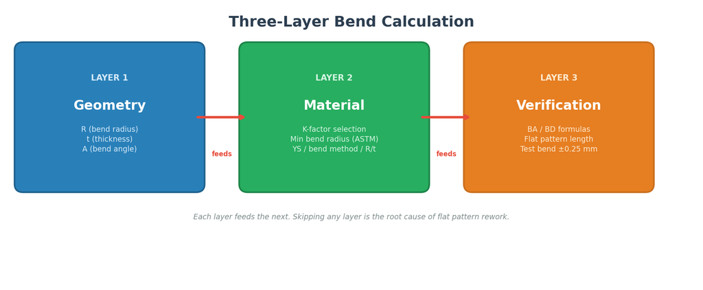
Table 1. Bend Parameter Quick Reference
| Parameter | Definition | Range | Governing Source |
| Bend radius (R) | Inside surface to center of curvature | 0.5t to 6t (material-dependent) | ASTM B209 bend factor N; shop validation |
| K-factor (K) | Neutral axis offset / thickness (δ / t) | 0.33 to 0.50 | Material YS, bend method, R/t ratio |
| Bend angle (A) | Included angle of the bend from flat | 0° to 180° | Part geometry (3D model) |
| Bend diameter factor (N) | ASTM 180° test pin diameter / t | 0 to 6 | ASTM B209 Table 3 / Table 4 |
| Y-factor | Alternate neutral axis scalar (K × π/2) | 0.52 to 0.79 | Legacy tables; confirm software convention |
2. K-Factor Charts by Material and Bend Method
K-factor values shift with material yield strength, bend method, and the ratio of bend radius to thickness (R/t). Air bending allows more neutral axis migration, producing lower K values. Harder alloys resist that migration, pushing K higher.
2.1 K-Factor Reference Table
Table 2. K-Factor Ranges by Material and Bend Method
| Material | Condition | YS (MPa) | Air Bending K | Bottom Bending K | Coining K |
| 5052 Aluminum | H32 | ≥ 160 (ASTM B209) | 0.33–0.36 | 0.38–0.42 | 0.42–0.44 |
| 6061 Aluminum | T6 | ≥ 240 (ASTM B209) | 0.36–0.39 | 0.40–0.44 | 0.44–0.46 |
| 1018 Cold-Rolled Steel | Annealed / Temper Rolled | 140–275 (ASTM A1008 Table 3) | 0.33–0.38 | 0.40–0.44 | 0.44–0.46 |
| 304 Stainless Steel | Annealed | ≥ 205 (ASTM A240) | 0.38–0.42 | 0.44–0.48 | 0.46–0.50 |
| Galvanized Steel (G90) | Temper Rolled | 205–345 | 0.35–0.40 | 0.42–0.46 | 0.44–0.48 |
Use the lower end of each range when R/t ≥ 2.0 and the upper end when R/t approaches the minimum. These ranges apply to 0.5 to 4.0 mm sheet. For plate above 4.0 mm, K trends toward 0.50 regardless of material.
2.2 K-Factor Selection Logic
For soft material air bending (5052-H32, 1018 CR): start at K = 0.33 to 0.36. For hard material bottom bending or coining (304 SS, 6061-T6): use K = 0.42 to 0.50. R/t ratio creates a secondary adjustment: below R/t = 1.5, K drops toward the lower bound; above R/t = 3.0, K rises toward the upper bound.
According to Dewey Wu, General Manager & senior mechanical engineer at EPOC CRAFTER: “On 304 stainless air bends at R = 1.5t, we measure K between 0.39 and 0.41 across batches. Switch to bottom bending at R = 2.0t on the same material and K jumps to 0.44 to 0.46. The difference produces 0.4 mm of flat pattern offset per bend on 2 mm sheet. Missing that offset on a four-bend enclosure puts the mating holes out of alignment by over 1.5 mm.”

Engineering note: V-die opening width affects K-factor in air bending. A wider V-die (8t to 12t opening) pushes K 0.01 to 0.03 higher than a narrow V-die (6t opening). If your shop switches dies between prototype and production, recalculate flat patterns for the new die width.
3. Minimum Bend Radius Chart by Material and Thickness
Minimum bend radius sets the lower limit of R for a given material, thickness, and grain orientation. Going below this limit fractures the outer fiber of the bend.
3.1 Bend Radius Chart
Table 3. Minimum Bend Radius by Material, Thickness, and Source
| Material | Thickness Range | Bend Factor N | Min Inside Radius R | Source | Decision |
| 5052-H32 | 0.40–0.63 mm | 0 | 0 (flat on itself) | ASTM B209 Table 3 | Tightest bends, complex enclosures |
| 5052-H32 | 0.63–1.20 mm | 1 | 0.5t | ASTM B209 Table 3 | Brackets, chassis folds |
| 5052-H32 | 1.20–3.20 mm | 2 | 1.0t | ASTM B209 Table 3 | General fabrication, flanges, panels |
| 5052-H32 | 3.20–6.30 mm | 3 | 1.5t | ASTM B209 Table 3 | Thick panels, structural brackets |
| 6061-T6 | 0.25–0.51 mm | 2 | 1.0t | ASTM B209 Table 4 | Thin structural skins |
| 6061-T6 | 0.53–0.91 mm | 3 | 1.5t | ASTM B209 Table 4 | Structural brackets |
| 6061-T6 | 0.94–1.63 mm | 4 | 2.0t | ASTM B209 Table 4 | Load-bearing formed parts |
| 6061-T6 | 1.65–3.25 mm | 5 | 2.5t | ASTM B209 Table 4 | Heavy brackets, mounting plates |
| 6061-T6 | 3.28–6.32 mm | 6 | 3.0t | ASTM B209 Table 4 | Thick structural; consider 5052 if R constrained |
| 304 SS | 0.5–3.0 mm | Not specified by ASTM A240 | ≥ 1.0t (shop-validated) | Shop practice | General stainless enclosures, food-grade panels |
| 304 SS | 3.0–6.0 mm | Not specified by ASTM A240 | ≥ 1.5t–2.0t | Shop practice | Thick stainless; springback compensation required |
| 1018 CR Steel | 0.5–3.0 mm | 180° flat-on-itself per A1008 | ≥ 0.5t–1.0t | ASTM A1008 §8.2.4; shop practice | Brackets, covers, general mild steel |
| Galvanized Steel | 0.5–3.0 mm | Varies by base grade | ≥ 1.0t–1.5t | Zinc coating integrity | HVAC panels, outdoor enclosures |
ASTM B209 values are 180° bend test parameters. For 304 SS and 1018 CR, ASTM A240 and A1008 do not provide R/t factors in this format; listed radii reflect press brake practice on annealed material bent perpendicular to rolling direction. Bending parallel to grain adds 0.5t to 1.0t to the practical minimum.
Quick-reference default: For 5052-H32 and 1018 cold-rolled in 0.8 to 3.0 mm, R = 1.0t works for most bracket, enclosure, and panel applications with cross-grain bending. 6061-T6 and 304 SS require material-specific R from Table 3. When in doubt, start at R = 1.5t and tighten after a test bend.
3.2 Grain Direction and Edge Condition Effects
Bending perpendicular to the rolling direction (cross-grain) allows tighter radii than bending parallel (with-grain). On 5052-H32 at 2.0 mm, cross-grain holds R = 1.0t; with-grain requires R = 1.5t. On 6061-T6, with-grain bending at the ASTM minimum R risks visible fracture. When part geometry forces a with-grain bend on 6061-T6, increase R by at least 1.0t above the ASTM minimum, or switch to 5052-H32 if the sheet metal material properties allow the lower yield strength.
Edge quality adds a second variable. Sheared edges with burrs on the outer (tension) surface concentrate stress and trigger cracking. Position burrs on the inside (compression) surface. 304 stainless amplifies this effect: ASTM A240/A240M-25 lists 304 elongation at ≥ 40% and UTS ≥ 515 MPa, but rapid work hardening near sheared edges locally reduces ductility. Deburring sheared edges before bending 304 below R = 1.5t prevents edge-initiated fracture.
Table 4. Grain Direction and Edge Condition Quick Reference
| Factor | Favorable Condition | Unfavorable Condition | Practical R Impact |
| Grain direction | Bend line perpendicular to rolling | Bend line parallel to rolling | Adds 0.5t to 1.0t |
| Edge condition | Laser-cut or deburred edge | Sheared edge, burr on tension side | Adds 0.5t to 1.5t |
| Combined worst case | Cross-grain + burr-in | With-grain + burr-out | Adds 1.0t to 2.5t |
For the tolerance impact of bend proximity on holes and features, see our guide on sheet metal tolerances for holes and features. EPOC CRAFTER’s sheet metal fabrication capabilities cover aluminum, stainless, and mild steel bending on CNC press brakes with tooling validated against Table 3.
4. Bend Allowance and Bend Deduction Formulas
Bend allowance (BA) is the arc length of the neutral axis through the bend zone. Bend deduction (BD) is the material “consumed” by bending, subtracted from outside leg dimensions to get the flat pattern length.
4.1 Bend Allowance (BA) Formula
BA = (π / 180) × (R + K × t) × A
Table 5. Bend Allowance Formula Variables
| Variable | Definition | Unit | Source |
| BA | Bend allowance (neutral axis arc length) | mm | Calculated |
| R | Inside bend radius | mm | Part geometry or Table 3 |
| K | K-factor (neutral axis offset / thickness) | Dimensionless | Table 2 |
| t | Sheet thickness (nominal) | mm | Material specification |
| A | Bend angle from flat | Degrees | Part geometry |
For a 90° bend, BA simplifies to (π / 2) × (R + K × t).
4.2 Bend Deduction (BD) and Outside Setback (OSSB)
OSSB = tan(A / 2) × (R + t). For a 90° bend, OSSB = R + t.
BD = 2 × OSSB − BA
Flat pattern length: L_flat = Leg 1 + Leg 2 − BD, where legs are measured from the inside of each bend to the flange edge.
Engineering note: Confusing inside leg measurement with outside leg measurement is the most common flat pattern input error. An outside-measured leg on a 90° bend in 2 mm stock at R = 2.0 mm overstates each leg by R + t = 4.0 mm. Always confirm whether your CAD dimensions reference the inside or outside face.
4.3 Three Worked Examples
Example 1: 2 mm 5052-H32, 90° air bend, K = 0.33
Given: t = 2.0 mm, R = 2.0 mm (1.0t per Table 3), A = 90°, K = 0.33. Legs: L1 = 25.0 mm, L2 = 40.0 mm (inside).
BA = (π / 2) × 2.66 = 4.178 mm. OSSB = 4.000 mm. BD = 3.822 mm. L_flat = 61.178 mm.
A test bend on this setup at EPOC CRAFTER’s press brake produced a measured flat of 61.0 to 61.3 mm across five samples. K = 0.33 is validated for this combination.
Example 2: 1.5 mm 304 Stainless, 90° bottom bend, K = 0.44
Given: t = 1.5 mm, R = 1.5 mm (1.0t, shop-validated), A = 90°, K = 0.44. Legs: L1 = 20.0 mm, L2 = 30.0 mm (inside).
BA = (π / 2) × 2.16 = 3.393 mm. OSSB = 3.000 mm. BD = 2.607 mm. L_flat = 47.393 mm.
Sensitivity check: Setting K to 0.33 instead of 0.44 shifts L_flat to 47.134 mm, a 0.259 mm deviation per bend. On a four-bend part, that compounds to ~1.0 mm total offset, enough to shift mounting holes out of position.
Example 3: 3 mm 6061-T6, 120° air bend, K = 0.38
Given: t = 3.0 mm, R = 7.5 mm (2.5t per Table 3), A = 120°, K = 0.38. Legs: L1 = 35.0 mm, L2 = 50.0 mm (inside).
BA = (π / 180) × 8.64 × 120 = 18.096 mm. OSSB = 1.732 × 10.5 = 18.186 mm. BD = 18.276 mm. L_flat = 66.724 mm.
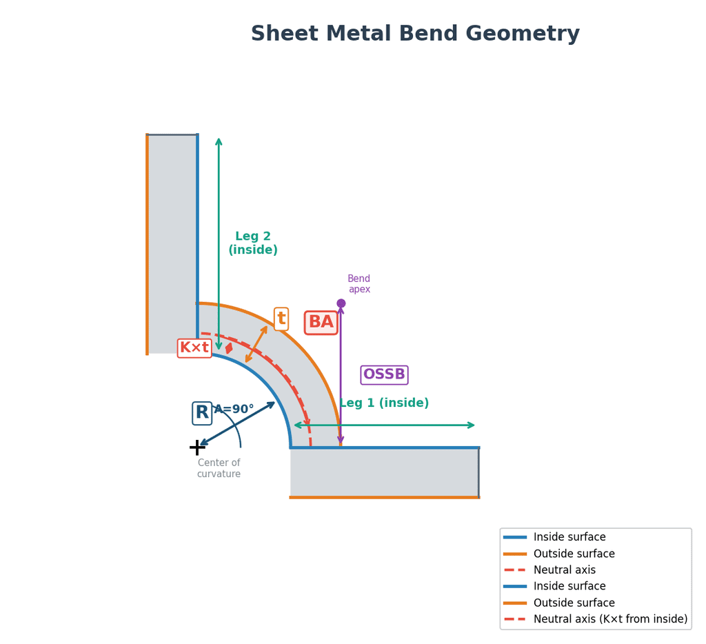
Table 6. Worked Examples Comparison
| Example | Material | t (mm) | R (mm) | R/t | A (°) | K | BA (mm) | BD (mm) | L_flat (mm) |
| 1 | 5052-H32 | 2.0 | 2.0 | 1.0 | 90 | 0.33 | 4.178 | 3.822 | 61.178 |
| 2 | 304 SS | 1.5 | 1.5 | 1.0 | 90 | 0.44 | 3.393 | 2.607 | 47.393 |
| 3 | 6061-T6 | 3.0 | 7.5 | 2.5 | 120 | 0.38 | 18.096 | 18.276 | 66.724 |
5. Flat Pattern Calculation and CAD Validation
Flat pattern length is the total blank dimension before bending. For a single bend: L_flat = Leg 1 + BA + Leg 2. For multi-bend parts: L_flat = Leg 1 + BA₁ + Leg 2 + BA₂ + Leg 3 + … + BAₙ + Leg (n+1). Each BA uses the R, K, and A specific to that bend.
5.1 CAD K-Factor Settings
Table 7. Default K-Factor Behavior in Common CAD Systems
| CAD Platform | Default K-Factor | What to Check |
| SolidWorks | 0.50 (gauge table dependent) | Confirm K vs. bend allowance input mode; SolidWorks allows BA override |
| Fusion 360 | 0.44 | Check whether K-factor field uses K or Y-factor convention |
| Creo / Pro-E | Varies by bend table | Review .bnd file for each material; legacy files may use outdated values |
Fusion 360’s default K = 0.44 works for mild steel air bends at R ≈ 1.0t. Applied to 5052-H32 air bends where correct K is closer to 0.33, the default overstates bend allowance by ~0.35 mm per 90° bend in 2 mm stock. On a four-bend bracket, the cumulative error reaches 1.4 mm. When you have shop data from a test bend, enter BA directly in SolidWorks to bypass the K-factor approximation.
Engineering note: CAD default K-factor values are starting points, not production specifications. A single test piece costs 5 to 10 minutes of press brake time and one blank. A batch cut to the wrong flat pattern costs material for the full run plus a second setup.
5.2 Verifying Flat Patterns Against Press Brake Results
A validated flat pattern matches the physical test bend within ±0.25 mm per bend. Cut one test blank, bend it on the production press brake, measure leg lengths and feature-to-feature distances. If deviation exceeds ±0.25 mm, adjust K-factor by 0.01 to 0.02 and retest. Two consecutive test bends within tolerance confirm K for that material/die combination.
Record validated K-factors in a material and die log indexed by grade, thickness, R/t, and die width. At EPOC CRAFTER, validated K-factor data covers the five materials in Table 2 across 0.5 to 4.0 mm, reducing first-article validation to one confirmation bend. For design rules governing hole placement and feature tolerances near bend zones, see our DFM design guidelines.
6. Common Errors and Troubleshooting
Most press brake rework on prototype runs traces back to four repeating errors.
Table 8. High-Frequency Bend Calculation Errors
| Error | Cause | Symptom | Fix |
| Flat pattern off by 0.3–1.5 mm/bend | Wrong K-factor (e.g., CAD default 0.44 for 5052-H32 air bend, correct K ≈ 0.33) | Leg lengths wrong; holes misaligned | Test bend, measure BA, back-calculate K, update CAD |
| Outer surface cracking | R below minimum (e.g., R = 1.0t on 6061-T6 where B209 requires R = 2.5t) | Visible fracture; part scrapped | Increase R per Table 3; confirm cross-grain bending |
| Intermittent cracking, same R | Bend line parallel to grain, or burr on tension side | Some blanks crack, others pass | Rotate blank 90° for cross-grain; flip burr to compression side |
| CAD flat pattern mismatch | K/Y-factor confused; inside vs. outside leg dimensions mixed | Consistent offset across all bends | Verify CAD field label (K vs. Y); confirm inside leg reference |
Springback and K-factor are independent parameters. K-factor controls flat pattern length; springback controls final bend angle after the press brake ram retracts. On 304 stainless at R = 1.5t, springback ranges from 2° to 5°. On 5052-H32 at R = 1.0t, springback is 0.5° to 1.5°. Correct springback with overbend angle at the press brake, not by changing K-factor.
Engineering note: When a bend cracks on a combination that should pass, check three things: grain direction (mill certificate), burr side (visual inspection), and actual thickness (micrometer at the bend zone) against certified values. EPOC CRAFTER’s materials and properties database lists thickness tolerance ranges by alloy for cross-reference. For tolerance specifications around bend zones, see our tolerances and standards reference.
7. FAQ
7.1 What is K-factor in sheet metal bending?
K-factor is the ratio of neutral axis offset (δ) to material thickness (t): K = δ / t. In a flat sheet, K = 0.50. During bending, the neutral axis shifts inward, dropping K below 0.50. Typical values range from 0.33 for soft alloys under air bending to 0.50 under coining. K-factor enters the bend allowance formula BA = (π / 180) × (R + K × t) × A, so an error in K directly scales flat pattern length. For 2 mm stock at 90°, each 0.01 change in K shifts BA by ~0.03 mm per bend.
7.2 How do you calculate bend allowance for sheet metal?
BA = (π / 180) × (R + K × t) × A. R is inside bend radius in mm, K is K-factor, t is thickness in mm, A is bend angle in degrees. For a 90° bend in 2 mm 5052-H32 with R = 2.0 mm and K = 0.33, BA = 4.178 mm. Flat pattern length = Leg 1 + Leg 2 − BD, where BD = 2 × OSSB − BA and OSSB = tan(A/2) × (R + t). Validated values from a test bend produce flat patterns accurate to ±0.25 mm per bend.
7.3 What is the minimum bend radius for aluminum sheet metal?
Per ASTM B209/B209M-21a, 5052-H32 at 1.20 to 3.20 mm achieves R = 1.0t (bend factor N = 2). 6061-T6 at the same range requires R = 2.0t to 2.5t (N = 4 to 5). 5052-H32 has lower yield strength (≥ 160 MPa) and better formability. Bending 6061-T6 below its ASTM minimum R fractures the outer surface. When tight R is needed and 6061-T6 strength is not required, 5052-H32 allows R as low as 0.5t below 1.20 mm.
7.4 K-factor vs Y-factor: what is the difference?
K = δ / t. Y = K × (π / 2) ≈ K × 1.5708. K = 0.33 corresponds to Y = 0.52. K = 0.50 corresponds to Y = 0.79. Entering K = 0.33 into a Y-factor field treats the neutral axis as if K = 0.21, producing a flat pattern that is too short and an oversized finished part. Always verify whether your CAD or bend table expects K or Y before entering a value.
7.5 How do you set K-factor in SolidWorks and Fusion 360?
In SolidWorks, open Sheet Metal > Bend Allowance tab and select K-Factor from the drop-down. SolidWorks also accepts direct BA entry from test bend data. In Fusion 360, open Sheet Metal Rules and override the default K = 0.44 per material. Fusion 360 uses K-factor convention (not Y-factor). After setting K, run a flat pattern preview, cross-check BA against your formula result, and verify leg dimensions match inside measurements.
7.6 Does grain direction affect bend radius?
Cross-grain bending (perpendicular to rolling direction) distributes strain more evenly, allowing tighter radii. With-grain bending raises practical minimum R by 0.5t to 1.0t. On 5052-H32 at 2.0 mm, cross-grain holds R = 1.0t; with-grain requires R = 1.5t. On 6061-T6, with-grain bending at the ASTM minimum R risks visible fracture. Adding 1.0t to minimum R is standard when grain orientation cannot be controlled.
7.7 What K-factor should you use for stainless steel?
For 304 SS (YS ≥ 205 MPa, UTS ≥ 515 MPa per ASTM A240/A240M-25), use K = 0.38 to 0.42 for air bending, K = 0.44 to 0.48 for bottom bending. 304’s high work-hardening rate pushes K higher than the same method on 5052-H32 or 1018 CR. Springback is also greater: the press brake must overbend by 2° to 5° depending on R/t. K-factor and springback are independent corrections: K controls flat pattern length, overbend controls final angle.
7.8 How do you calculate flat pattern length for multiple bends?
L_flat = Leg 1 + BA₁ + Leg 2 + BA₂ + … + BAₙ + Leg (n+1). Each BA uses R, K, and A specific to that bend. A four-bend bracket in 2 mm 5052-H32 at K = 0.33, R = 2.0 mm has total BA = 4 × 4.178 = 16.712 mm. Measure all legs from the inside face. Double-counting the bend zone overstates flat length by R + t per duplicated segment.
Download the EPOC CRAFTER Bend Calculation Quick-Reference Sheet: K-factor values for five materials, minimum bend radius charts, and the BA/BD/OSSB formulas on a single printable page for your shop floor. Download the Quick-Reference PDF
Related Resources
Related Capability: EPOC CRAFTER Sheet Metal Fabrication — CNC press brake bending, laser cutting, and forming for aluminum, stainless, and mild steel sheet from 0.5 mm to 6.0 mm.
Related Article: Sheet Metal Design Guidelines — The complete DFM rulebook covering bending, feature placement, material thickness, and tolerance strategy.
Related Article: Sheet Metal Tolerances and Feature Design — How tolerances stack across bends and cut features, with ISO 2768 charts and hole spacing rules.
Related Material Guide: Sheet Metal Materials Guide — 5052, 6061, 304, 1018, and galvanized steel compared on strength, formability, weldability, and cost.
Ready to Quote Your CNC Prototype?
Upload your STEP file and get a DFM review + quote within 12 hours.
No tooling cost. Minimum 1 part.
