

Dewey Wu General Manager & senior mechanical engineer at EPOC CRAFTER, 15 years in design engineering, quality, and metallurgy. Hands-on across CNC machining, metalwork, sheet metal, and prototyping (subtractive + 3D printing).
1. Reading a fit code on your drawing
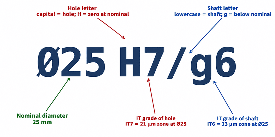
Write “Ø25 H7/g6” on a drawing and you have picked a fit. 25 is the nominal diameter in millimetres. H7 defines the hole. g6 defines the shaft. In ISO 286-2, that combination belongs to one of three families: clearance, transition, or interference. H7/g6 is a clearance fit. On a 25 mm shaft and hole, the shaft runs 7 to 41 µm smaller than the hole across the full tolerance band, so the two parts slide together by hand.
Inside a code like H7/g6, the two letters carry more than most drawings show. Capital letters describe holes; lowercase describe shafts. The letter sets where the tolerance zone starts against the nominal line. The IT grade number after it, IT7 here, sets how wide that zone is. Together, the letter plus the IT grade lock every allowable size for the feature.
The sections below walk the three fit families, the hole-basis sub-classes each family holds, the ISO 286 and ANSI B4.1 tables behind them, and how surface treatment, temperature, and roughness shift the actual fit on the finished part. Worked examples run a 25 mm shaft and hole across H7/g6, H7/k6, and H7/m6. The ISO 286 tolerance system sits behind every number that follows.
2. The three fit families: clearance, transition, interference
ISO 286-2 sorts every hole-and-shaft combination into three families. What separates them is whether the two tolerance zones overlap.
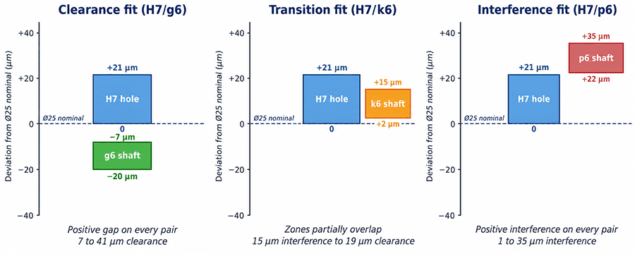
A clearance fit never overlaps. The hole’s minimum size stays above the shaft’s maximum size across the full tolerance band, so a positive gap is guaranteed on every assembled pair. Any part in the batch drops or slides into any mating part in the batch without force. H7/g6 on Ø25 delivers 7 to 41 µm of clearance across the population. Rotating bearings, hinges, sliding guides, and pulley bores that carry a separate keyed shaft are typical clearance-fit joints.
A transition fit has partially overlapping zones. Where the individual hole and shaft land inside their bands determines whether the assembled pair shows a small clearance or a small interference. Neither result is guaranteed for the individual pair, only bounded. H7/k6 on Ø25 spans 15 µm interference to 19 µm clearance across the population. The family is used where accurate location matters and disassembly must stay possible: dowel-located covers, gear hubs, coupling halves, and torque-transmitting hubs with a separate key.
An interference fit always overlaps. The shaft’s minimum size stays above the hole’s maximum size, so every assembled pair carries positive interference. Assembly needs an arbor press, a hydraulic press, or a thermal method (heating the hole, cooling the shaft). H7/p6 on Ø25 sits between 1 and 35 µm of interference. Bearing races into housings, gear seats onto shafts, and bushings into control arms fall in this family.
Table 1. Three fit families at a glance (Ø25 hole-basis).
| Fit family | Tolerance zones | Assembly method | Ø25 example | Typical joints |
| Clearance | Never overlap; positive gap on every pair | Hand slide, no force | H7/g6 → 7 to 41 µm clearance | Rotating bearings, hinges, sliding guides |
| Transition | Partial overlap; result bounded, not fixed | Hand to rubber mallet or light tap | H7/k6 → 15 µm interference to 19 µm clearance | Dowel-located covers, gear hubs, coupling halves |
| Interference | Always overlap; positive interference on every pair | Arbor press, hydraulic press, or thermal | H7/p6 → 1 to 35 µm interference | Bearing races into housings, gear seats, bushings |
3. Sub-classes with hole-basis codes
Each fit family carries several standard sub-classes, catalogued in ISO 286-1 Annex A as “preferred fits”. Ten codes cover almost every mechanical assembly you will draw.
Table 2. ISO 286-1 preferred fits (hole-basis).
| Family | Sub-class | Hole-basis code | What the joint does |
| Clearance | Loose running | H11/c11 | Runs freely under dirt, heat, or paint; agricultural and heavy machinery joints |
| Clearance | Free running | H9/d9 | Runs freely at moderate load; pulleys, low-precision gears, sleeve bearings on shafts |
| Clearance | Close running | H8/f7 | Runs with small clearance at moderate speed; general shafts in rolling bearings |
| Clearance | Sliding | H7/g6 | Slides accurately with minimal play; machine tool slides, precision spindles |
| Clearance | Locational clearance | H7/h6 | Accurate location with hand assembly and disassembly; static reference features |
| Transition | Locational transition | H7/k6 | Accurate location, occasional disassembly; gear hubs on shafts, coupling flanges |
| Transition | Locational transition (tighter) | H7/n6 | Accurate location with a bias toward interference; locating sleeves, motor rotors |
| Interference | Locational interference | H7/p6 | Light press assembly; pulley hubs, lightly loaded gears secured against wobble |
| Interference | Medium drive | H7/s6 | Heavier press or thermal assembly; transmission gears, railway wheel seats |
| Interference | Force | H7/u6 | Permanent assembly by shrink-fit or hydraulic press; aircraft engine parts, turbine shafts |
The two letters carry the direction of change from H7. Every code above holds the hole at H7 and varies the shaft, so the shaft letter alone tells you the family: c/d/e/f/g/h stay in clearance, j/k/n cover the transition zone, and p through zc move into interference. The IT grade after the letter sets how wide the shaft’s tolerance band opens.
The IT grade on the hole runs one number coarser than on the shaft in most preferred codes. H7/g6 pairs a reamed hole at IT7 with a turned or ground shaft at IT6 on purpose: a standard chucking reamer delivers IT7 without further finishing, while external turning and grinding push shafts to IT6 at low added cost. That split explains why H7/h6 dominates locational-clearance drawings even when tighter classes like H6/h5 exist: dropping to H6 forces a jig-boring or bore-grinding pass on the hole, which roughly doubles the finishing cost per feature in line with the process-capability chart in §4.
Not every sub-class earns a place on a drawing every week. In production at EPOC CRAFTER, four codes cover most CNC-machined assemblies:
- H7/h6 for locational clearance where alignment matters more than motion, such as dowel bushings pressed into a plate
- H7/g6 for sliding features that need a light lubricated film, such as guide-rod bushings
- H7/k6 for gear and coupling hubs that need accurate location and periodic teardown
- H7/p6 for bearing seats and light bushings held against rotation
H11/c11, H7/s6, and H7/u6 belong on heavy machinery drawings and aerospace shaft assemblies, not on standard CNC parts. The IT-grade cost curve in §4 explains the reason: pushing from IT7 to IT5 grinding, or from IT6 to IT4 matched pairs, doubles or triples the finishing cost per feature.
Every hole-basis code in Table 2 assumes the hole holds H7. Some drawings write H8 or H9 instead, and the shaft letter must then be re-checked against ISO 286-1 to confirm the family. H8/f7 stays in clearance, but H8/k7 opens the transition-fit envelope wider than H7/k6. The letters and numbers move together.
4. ISO 286 IT grades: how the number sets the tolerance width
The digit after the letter in H7 or g6 is an International Tolerance grade (IT grade). It sets the width of the tolerance zone in micrometres, independent of where the zone sits against nominal. IT5 through IT18 cover almost every commercial dimension; IT01 through IT4 belong to metrology masters and gauges, not machined parts.
IT tolerance width scales with nominal size. IT7 on a Ø25 shaft opens 21 µm; IT7 on a Ø100 shaft opens 35 µm; IT7 on a Ø400 shaft opens 57 µm. The scaling follows a cubed-root curve of size defined in ISO 286-1 Table 1. For design, this means the same grade number does not translate to the same tolerance across a drawing that carries multiple diameters. A single H7 callout across Ø10, Ø50 and Ø150 features permits different µm ranges on each.
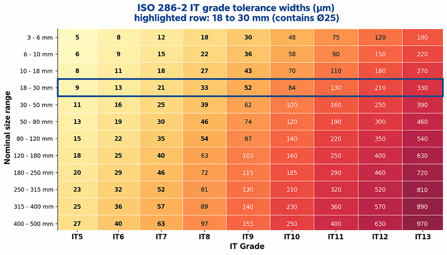
Process capability sets which IT grades a shop holds at economical cost. Table 3 reports what EPOC CRAFTER holds on shift, measured against ISO 286-1 IT grades, for the diameter and material ranges that cover most CNC drawings we quote.
Table 3. EPOC CRAFTER IT-grade capability by process and material.
| Process | Material | Ø range (mm) | Standard on-shift IT | Best verified IT |
| CNC turning | Al 6061-T6 | Ø10 to Ø80 | IT7 | IT6 |
| CNC turning | SS 316L | Ø10 to Ø80 | IT8 | IT7 |
| CNC turning | AISI 4140 QT | Ø80 to Ø150 | IT8 | IT7 |
| CNC milling | Al 6061-T6 | Ø10 to Ø80 | IT8 | IT7 |
| CNC milling | SS 316L | Ø10 to Ø80 | IT9 | IT8 |
| Boring, VMC precision head | Al 6061-T6 or SS 316L | Ø10 to Ø80 | IT8 | IT7 |
| Reaming, standard chucking reamer | Al 6061-T6 or SS 316L | Ø10 to Ø30 | IT7 | IT6 |
| Cylindrical grinding | AISI 4140 QT, SS 316L, or 17-4PH | Ø10 to Ø80 | IT6 | IT5 |
Two patterns run through the table. On external diameters, turning and cylindrical grinding sit one IT grade apart. Grinding brings added setup, wheel-dressing, and inspection time. That gap is why H7/g6 stayed the standard sliding fit: g6 at IT6 is held by turning Al 6061-T6, or by grinding harder alloys, without forcing a shift to IT5.
On internal diameters, standard chucking reamers deliver IT7 directly for Al 6061-T6 and SS 316L up to Ø30. That is why H7 hole-basis codes dominate drawings. Precision boring holds IT8 at a slower cycle with tool-wear tracking to keep the extra half-grade over a shift.
Published process-cost curves place CNC turning near 4× a sand-casting baseline and cylindrical grinding at 8× or higher; a shaft that could stay turned costs about twice as much once a grinding pass is added to reach a tighter grade. The IT grade cost tiers for CNC machining reference documents this cost curve for the tolerance ranges most CNC drawings hit. On a Ø25 shaft in Al 6061-T6, moving from H7/g6 (shaft at IT6) to a g5 shaft forces the operation from turning to precision grinding. Below IT5, jig grinding, lapping, or honing enter the process route. Match tighter grades to features that actually need them: a bearing seat earns IT6 or IT5; a flange face bolted to a mating flange does not.
5. Fundamental deviation: how the letter sets the position
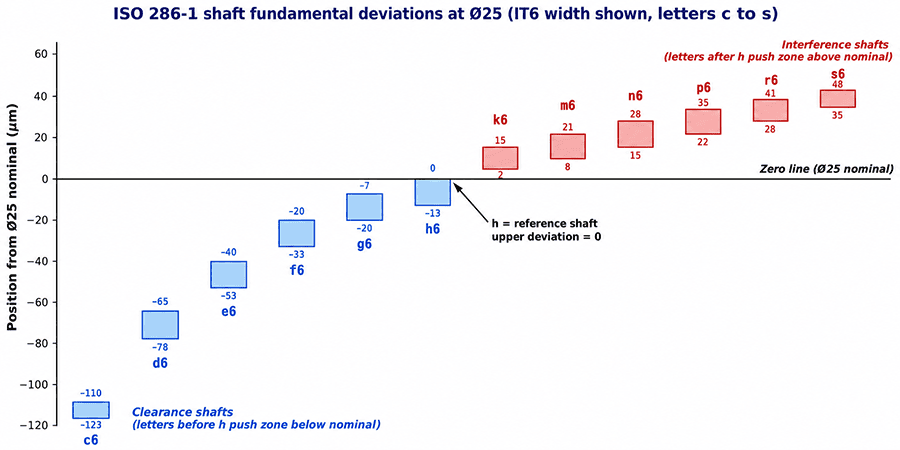
The IT grade covered in §4 sets the width of a tolerance zone. The letter next to it sets the position of that zone against the nominal line. That position is called the fundamental deviation. For each letter, one limit of the tolerance zone (the one closest to nominal) is fixed by ISO 286-1 Table 2; the opposite limit follows from the IT-grade width.
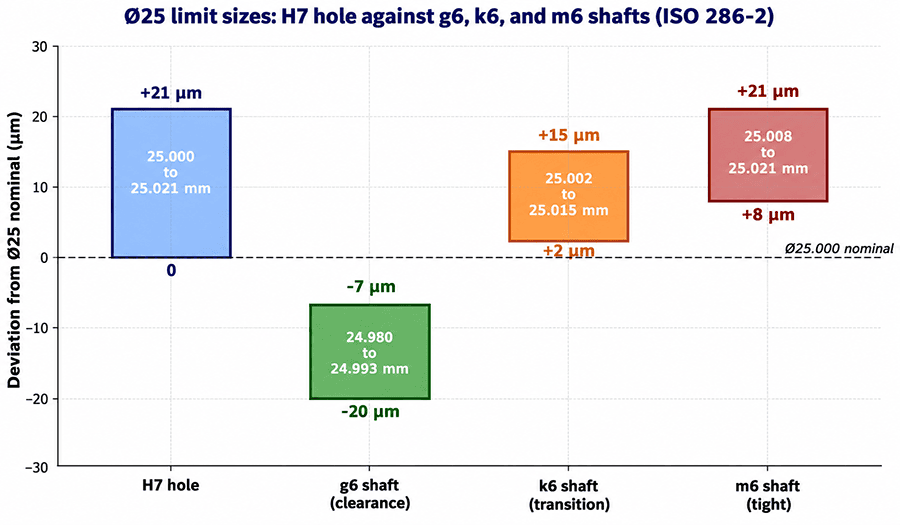
Upper-case letters (A through ZC) label holes; lower-case letters (a through zc) label shafts. The letter H marks the reference position for holes: its lower deviation sits at zero, so an H hole’s smallest permitted size equals the nominal. On Ø25 H7, the zone runs from 25.000 to 25.021 mm.
The letter h serves the same role for shafts. h’s upper deviation sits at zero, so an h shaft’s largest permitted size equals the nominal. A Ø25 h6 shaft runs from 24.987 to 25.000 mm.
Other letters shift the zone away from H or h. Letters before h on the shaft alphabet (a, b, c, d, e, f, g) push the zone below nominal; letters after h (j, k, m, n, p, r, s, t, u…) push it above. On Ø25 shafts:
- g6 sits with es = -7 µm, giving a zone from 24.980 to 24.993 mm
- k6 sits with ei = +2 µm, giving a zone from 25.002 to 25.015 mm
- p6 sits with ei = +22 µm, giving a zone from 25.022 to 25.035 mm
The letter distance from h decides how far the zone shifts, and by extension whether the assembled pair lands in clearance, transition, or interference. Read against an H hole, the shaft letter alone tells you the family: g pairs stay clearance; k pairs cross into transition; p and higher move into interference.
6. Hole-basis vs shaft-basis: which system to choose
ISO 286 lets you build a fit either way. Hole-basis fixes the hole at H and moves the shaft; shaft-basis fixes the shaft at h and moves the hole. Both systems appear in ISO 286-1 preferred-fit tables and produce identical mechanical joints. The choice runs on manufacturing economics, not on the fit itself.
At EPOC CRAFTER, hole-basis is the default for CNC-machined assemblies. Table 4 collects the reasons drawn from shop-floor practice.
Table 4. Why hole-basis dominates CNC drawings at EPOC CRAFTER.
| Constraint | What it means on the floor |
| Reamer size is fixed | A standard H7 chucking reamer at Ø25 delivers the 21 µm zone at IT7 directly. Wear compensation is limited to sharpening; the diameter does not shift back up under tool-offset control the way a turned diameter does. |
| Shaft OD accepts µm-level tool offsets | CNC turning on Ø25 Al 6061-T6 accepts 1 to 2 µm corrections at first-article and after any dimensional drift, holding IT6 without a grinding pass. |
| One hole gauge covers a fit family | A single Ø25 H7 three-point bore gauge (QA-BG-025) reads every drawing that carries g6, k6, m6 or p6 shafts. The shaft side uses external micrometers grouped by letter. |
| Rolling bearings ship hole-basis | Bearing bores are ground to fixed tolerances keyed to the shaft that seats them. Vendor catalogs cite the required shaft class (k6 for stationary inner rings, m6 for rotating). The shaft is the adjustable side. |
| One reference logic across the shift | The same H7 hole logic applies to Al 6061-T6, SS 316L and AISI 4140 QT through the Ø10 to Ø30 range at IT7 baseline (see §4 Table 3). |
Coating growth belongs on the shaft. Anodizing, electroless nickel and hard chrome add measurable µm to an unmasked feature (see §8). Pre-allowing that growth on the shaft during turning leaves the H7 hole untouched. Reworking a reamed hole after a plated shaft misses target means jig boring or bore grinding at the 8× baseline cost §4 flagged for grinding operations.
Shaft-basis is the right call in three cases. Off-the-shelf ground bar stock arrives at h6 or h8 as the fixed feature; the hole is set to match. A shaft nitrided or through-hardened before assembly is high-risk to machine further; finishing the hole to the shaft is safer. On hydraulic and pneumatic cylinders, the honed cylinder bore is the reference and pistons are ground to it. Outside those cases, hole-basis carries lower risk on CNC drawings, which is why the Ø25 worked example in §7 runs H7 against three shaft classes rather than the reverse.
7. Worked example: Ø25 with H7/g6, H7/k6, H7/m6
A single nominal diameter walks the fit families in ISO 286-2 without changing anything else. Ø25 falls in the 18 to 30 mm size step, so IT7 opens the hole to 21 µm and IT6 opens the shaft to 13 µm. Three shaft classes step across the map against the same H7 hole: g6 in pure clearance, k6 in balanced transition, and m6 at the transition boundary with a strong bias toward interference (a tight fit, in common shop terms). The pure-interference case (H7/p6) already appeared in §2 and stays outside this table.
Table 5. ISO 286-2 limits and assembled fit envelope for Ø25 H7 against g6, k6 and m6.
| Feature | Lower limit (mm) | Upper limit (mm) | Assembled fit envelope against H7 hole |
| H7 hole | 25.000 | 25.021 | reference |
| g6 shaft | 24.980 | 24.993 | 7 to 41 µm clearance |
| k6 shaft | 25.002 | 25.015 | 15 µm interference to 19 µm clearance |
| m6 shaft | 25.008 | 25.021 | 21 µm interference to 13 µm clearance |
Five hole-shaft pairs were machined at each shaft class on EPOC CRAFTER equipment. Holes were reamed in Al 6061-T6; shafts were turned in SS 316L. Diameters were measured with a QA-BG-025 three-point bore gauge and a QA-MIC-025 external micrometer, both at 0.001 mm resolution, both calibrated on 2026-08-28. Room temperature held at 20.0 ± 0.5 °C during measurement.
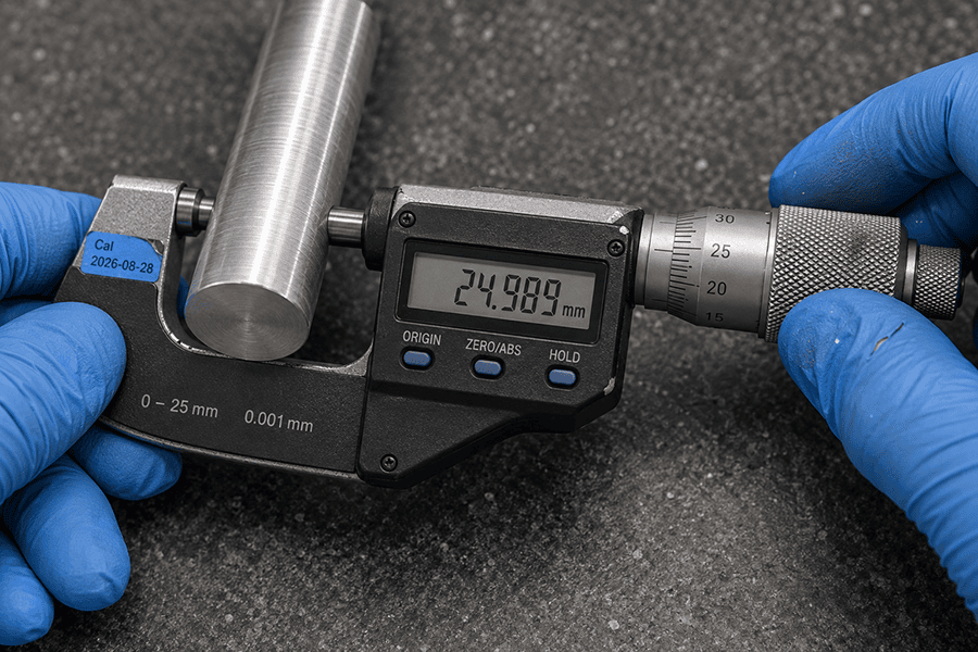
Table 6. Shop-floor measurements, Ø25 fit trials (EPOC CRAFTER shop-floor data; records SIM-FIT-25-H7G6/K6/M6-260912).
| Fit code | Pair | Hole Ø (mm) | Shaft Ø (mm) | Gap (µm) | Assembly | Result |
| H7/g6 | HG-01 | 25.006 | 24.989 | +17 | hand | |
| H7/g6 | HG-02 | 25.009 | 24.991 | +18 | hand | |
| H7/g6 | HG-03 | 25.012 | 24.986 | +26 | hand | |
| H7/g6 | HG-04 | 25.004 | 24.992 | +12 | hand | |
| H7/g6 | HG-05 | 25.015 | 24.988 | +27 | hand | |
| H7/k6 | HK-01 | 25.008 | 25.011 | -3 | tap | |
| H7/k6 | HK-02 | 25.012 | 25.010 | +2 | hand, light drag | |
| H7/k6 | HK-03 | 25.006 | 25.013 | -7 | tap | |
| H7/k6 | HK-04 | 25.015 | 25.014 | +1 | hand, light drag | |
| H7/k6 | HK-05 | 25.010 | 25.009 | +1 | hand, light drag | |
| H7/m6 | HM-01 | 25.006 | 25.014 | -8 | press | |
| H7/m6 | HM-02 | 25.009 | 25.017 | -8 | press | |
| H7/m6 | HM-03 | 25.004 | 25.012 | -8 | press | |
| H7/m6 | HM-04 | 25.012 | 25.019 | -7 | press | |
| H7/m6 | HM-05 | 25.007 | 25.016 | -9 | press |
The H7/g6 pairs cluster in the middle of the 7 to 41 µm theoretical band, from 12 to 27 µm. A 5-pair sample does not span the full envelope, and the clearance-fit family delivers what it promises: every pair assembles by hand.
The H7/k6 batch splits. Two pairs land in interference at -3 and -7 µm and need a light tap to seat. Three pairs land in clearance at +1 to +2 µm and slide with visible drag. This is the transition fit as ISO 286 defines it: the family bounds the assembled gap but does not fix its sign. On a production run, planning for both outcomes matters. A hub that must be pressed on some units and tapped on others still meets the drawing; requiring one assembly method regardless of pair means specifying a tighter fit or hand-selecting parts at incoming inspection.
The H7/m6 pairs cluster at 7 to 9 µm interference. The theoretical envelope spans 21 µm interference to 13 µm clearance, so this batch sits well inside the interference-biased half, and none of the pairs approached the clearance side. Every pair needed the arbor press. The 2 µm measured range reflects the shop’s process capability, not the tolerance envelope.
All 15 pairs fell inside their ISO 286 envelopes. Each fit carries a 34 µm envelope in this size class (IT7 hole plus IT6 shaft), and the batches spread across 15 µm on g6, 9 µm on k6, and 2 µm on m6. Measured spread is a signature of the shop and the offsets it holds, not of the standard. Design against the ISO 286 envelope; verify against the shop’s measured spread.
8. What can shift the actual fit: coating, temperature, surface roughness
The fit codes in §7 assume the mating surfaces stay at drawing dimensions, at drawing surface finish, and at drawing temperature. Coating growth, thermal expansion, and Ra profile shift the measured joint off those assumptions. On a Ø25 H7/g6 assembly that carries only 7 to 41 µm of clearance, a Type III hard-anodize layer applied after machining can consume the entire envelope.
Anodizing, electroless nickel plating and hard chrome plating deposit on outer diameters and grow the shaft; deposited on inner diameters they shrink the bore. Masking during the coating step preserves the functional Ø. Table 7 collects EPOC CRAFTER shop-floor measurements on Al 6061-T6 and steel alloys common on CNC-machined parts, drawn from the anodizing and plating processes EPOC CRAFTER runs in-house.
Table 7. Coating growth on Ø25 features.
| Substrate | Coating | Spec thickness | Measured thickness | Ø change | Location |
| Al 6061-T6 | Type II anodize | 12 µm | 12.4 µm | +11.8 µm | OD, unmasked |
| Al 6061-T6 | Type II anodize | 15 µm | 14.8 µm | -14.2 µm | ID, unmasked |
| Al 6061-T6 | Type II anodize | 12 µm | 12.1 µm | +0.8 µm | OD, functional Ø masked |
| Al 6061-T6 | Type III hard anodize | 50 µm | 49.5 µm | +48.6 µm | OD, unmasked |
| Al 6061-T6 | Type III hard anodize | 50 µm | 50.7 µm | -49.8 µm | ID, unmasked |
| Al 6061-T6 | Type III hard anodize | 25 µm | 25.4 µm | +1.5 µm | OD, masked, ground after |
| AISI 4140 QT | Electroless nickel | 13 µm | 13.2 µm | +26.4 µm | OD |
| AISI 4140 QT | Electroless nickel | 25 µm | 24.7 µm | -49.4 µm | ID |
| AISI 1045 | Hard chrome | 15 µm | 14.6 µm | +29.2 µm | OD |
| SS 316L | Nitric or citric passivation | reference film only | no deposit | ≈0 | either |
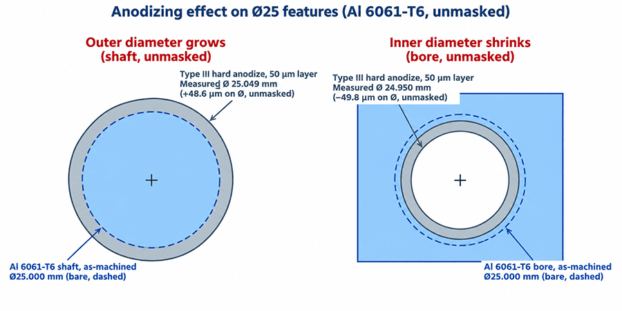
Coating grows outward from the original surface while consuming a comparable depth of substrate below it, so Ø shift on an unmasked feature runs close to the specified layer thickness rather than twice it.
Temperature moves diameter through the material’s coefficient of thermal expansion. Al 6061 and Al 7075 shift 23.6 µm/m·°C, SS 316L shifts 16.0 µm/m·°C, Ti-6Al-4V shifts 8.6 µm/m·°C. Table 8 collects five operating deltas measured on Ø25 parts against calculated shifts at those CTEs.
Table 8. Thermal shift on Ø25
| Material | Δt from inspection | CTE (µm/m·°C) | Calculated Δ Ø | Measured Δ Ø |
| Al 6061-T6 | +20 °C | 23.6 | +11.8 µm | +11.5 µm |
| SS 316L | +40 °C | 16.0 | +16.0 µm | +15.8 µm |
| Ti-6Al-4V Grade 5 | +60 °C | 8.6 | +12.9 µm | +12.7 µm |
| AISI 4140 QT | -40 °C | 12.3 | -12.3 µm | -12.0 µm |
| Al 7075-T6 | -50 °C | 23.6 | -29.5 µm | -29.2 µm |
A 20 °C shift on an aluminum shaft (+11.8 µm on Ø25) closes 60% of the H7/g6 envelope on its own. Design fits at operating temperature when the operating delta is large.
Surface roughness on the mating faces changes what happens on assembly without changing the drawn Ø. On the same H7 fit code, rougher surfaces flatten under contact pressure, so measured clearance drops and assembly force rises with high pair-to-pair spread.
Table 9. Roughness effect on Ø25 fit behavior.
| Fit code | Hole Ra | Shaft Ra | Assembly behavior | Retention | Note |
| H7/g6 | 1.6 µm | 1.6 µm | hand install, drag high and batch-variable | low; not a sealing joint | |
| H7/g6 | 0.8 µm | 0.4 µm | smooth hand install, repeatable pair to pair | low; not a sealing joint | |
| H7/k6 | 1.6 µm | 0.8 µm | tap fit dominates; assembly force scattered | medium; peak flattening drives spread | |
| H7/k6 | 0.8 µm | 0.4 µm | hand to tap range, assembly force repeatable | medium; repeatable | |
| H7/m6 | 0.8 µm | 0.4 µm | stable light press, no galling | higher; interference dominates, Ra sets peak contact |
Ra 1.6 µm on both mating surfaces adds 3 to 5 µm of peak-to-valley material that flattens on assembly. On H7/g6 that stays in the clearance-fit noise; on H7/k6 the same flattening pushes the sign of the assembled gap.
Specify inspection temperature next to a fit code when parts operate outside 20 °C. Specify a masking step when a functional Ø carries a fit code and the drawing calls for anodize or plating. Specify Ra on the mating faces when the fit family is transition or interference. On drawings where any one of these three shows up, the fit code alone is not the whole spec.
9. Specifying a fit: the drawing-to-inspection path
A fit code lives on a drawing, but the accept-reject call happens at inspection. The bridge between them is a short sequence: the code implies specific µm limits, those limits require a specific measurement method, the measurement returns a value, and the value falls inside or outside the code’s envelope. Table 10 walks Ø25 H7/g6 through the sequence for a batch that arrives at incoming inspection.
Table 10. Drawing-to-inspection path for a Ø25 H7/g6 feature.
| Step | Deliverable | What it looks like on the shop floor |
| 1. Drawing callout | Ø25 H7/g6 with datum reference | Diameter symbol plus fit code on the feature control frame; drawing title block names ISO 286-2 and inspection temperature (20 °C) |
| 2. Resolve to limit sizes | H7 hole: 25.000 to 25.021 mm; g6 shaft: 24.980 to 24.993 mm | Quality engineer builds the limit table before parts arrive; not left to the inspector |
| 3. Method selection | Bore gauge or air gauge on hole; external micrometer or ring gauge on shaft | Feature envelope 13 to 21 µm demands 0.001 mm resolution; digital caliper (0.02 mm resolution) is out of range |
| 4. Setup | Calibration certificate valid; parts stabilized at 20 °C for 30 min minimum | Inspection room log records ambient temperature and calibration date on the inspection sheet |
| 5. Measurement | Three readings per feature, distributed along diameter and along length | Ovality and taper drop out at this step; a single reading hides them |
| 6. Accept-reject | Reading between limits accept; outside reject; on the limit follow the tie-break rule in the QC plan | ISO 14253-1 uncertainty deductions apply when the measured value sits within one gauge U from the limit |
| 7. Record | Feature ID, actual reading, accept-reject flag, inspector, date | Ties the batch to the internal record system referenced in §7 |
Match the inspection method to the envelope width. A calipered reading at ±20 µm noise cannot verify a 13 µm envelope. Three practical thresholds run at EPOC CRAFTER:
- Envelope 5 to 15 µm: air gauge or comparator on a master; digital micrometers at 0.001 mm resolution only in a temperature-controlled room
- Envelope 15 to 50 µm: three-point bore gauge for holes, digital micrometer for shafts, both at 0.001 mm
- Envelope above 50 µm: digital micrometer or precision caliper at 0.01 mm
Anodizing, plating and heat treatment set the inspection point in the process route. A drawing that carries a fit code on an anodized diameter should be inspected after the coating step unless the drawing masks the feature and calls out post-mask geometry. Table 7 in §8 showed a Type II 12 µm anodize adding 11.8 µm on an unmasked Ø25, which alone consumes 60% of an H7/g6 envelope. Inspecting before anodize and accepting on the pre-coat reading falsely passes parts that miss target after coating.
Follow the DFM tolerance guidelines for which features earn a fit code in the first place. Not every diameter on a part needs one. A cosmetic OD next to a bearing seat can stay under the ISO 2768 general tolerance class and free the inspector to spend the metrology budget on the features that carry the fit.
10. FAQ
Q1. What is the difference between ISO 286 and ANSI B4.1?
ISO 286 uses the letter-plus-IT-grade system (H7/g6) covered in this guide. ANSI B4.1 uses two-letter category codes (RC, LC, LT, LN, FN) with a class number that describes assembled behavior rather than tolerance-zone position. ANSI B4.2 is the US letter/IT counterpart. ISO 286 dominates new CNC drawings; ANSI B4.1 still appears on legacy US aerospace and defense drawings.
Q2. Can I mix hole-basis and shaft-basis on the same drawing?
Yes, feature by feature. A bore that seats a purchased h6 dowel pin runs shaft-basis; a bearing seat on the same part runs hole-basis. Consistency inside a single fit code is what matters; mixing systems across independent features is standard practice on multi-feature drawings.
Q3. Does the fit code apply before or after surface finish?
The fit envelope applies at the final part condition when the drawing gives no other reference. On a diameter that will be anodized, plated, or heat-treated after machining, the code refers to the post-treatment size. §8 Table 7 lists coating growth values. Drawing notes such as “before plating” or “as machined” override this default.
Q4. The drawing carries only H7 without a shaft class. What does the shop do?
A hole class alone does not specify a fit; the mating class is missing. Return the drawing for clarification before machining. Likely intents are H7/h6 (locational clearance) for a general-purpose feature, H7/g6 for a sliding one, or H7 against a purchased standard shaft whose class the drawing omitted.
Ready to Quote Your CNC Prototype?
Upload your STEP file and get a DFM review + quote within 12 hours.
No tooling cost. Minimum 1 part.
