

Dewey Wu General Manager & senior mechanical engineer at EPOC CRAFTER, 15 years in design engineering, quality, and metallurgy. Hands-on across CNC machining, metalwork, sheet metal, and prototyping (subtractive + 3D printing).
PETG vs PLA starts with the part requirement, not a universal strength ranking. PLA can provide greater tensile strength and stiffness, while PETG may perform better when ductility, impact resistance, or heat exposure matters. The right choice depends on the material grade, print orientation, part geometry, and service conditions.
In an EPOC CRAFTER electronics bracket case, PLA showed higher XY tensile strength, but PETG met the required dimensional stability at 55°C. The final material decision came down to part performance, not tensile strength alone.
1. PETG vs PLA: Key Differences at a Glance
PLA generally suits rigid prototypes and indoor models where printing simplicity matters. PETG often offers greater ductility and better resistance to deformation at elevated temperatures, although the result depends on the formulation and printing process.
| Comparison factor | PLA | PETG |
| Tensile strength | Can exceed PETG under comparable test conditions | Not inherently stronger than PLA |
| Tensile stiffness | Often higher for common unfilled grades | Often lower for common unfilled grades |
| Ductility | Typically lower elongation at break | Often higher elongation at break |
| Impact resistance | Can fracture under concentrated impact | Often more resistant to impact |
| Heat resistance | May lose dimensional stability under elevated temperature and load | Often maintains dimensional stability at higher temperatures |
| Printability | Generally easier to print with less stringing | Requires closer control of extrusion, cooling, and stringing |
| Layer bonding | Depends on deposition temperature, orientation, and process conditions | Depends on deposition temperature, orientation, and process conditions |
| Moisture control | Storage and drying conditions affect print consistency | Storage and drying conditions affect print consistency |
| Dimensional accuracy | Can produce accurate features with controlled printing conditions | Can produce accurate features, but cooling and extrusion must be controlled |
| Typical applications | Rigid prototypes, visual models, indoor fixtures | Protective covers, functional brackets, and parts exposed to moderate heat |
The comparison describes tendencies, not guaranteed limits. A specific formulation, filler system, print orientation, or thermal treatment can change the result.
2. Material Identity: What Are PETG and PLA?
PLA (polylactic acid) is a thermoplastic polyester commonly used in FDM 3D printing. PETG generally refers to glycol-modified PET-based copolyester formulations. Both are available as 3D printing filaments, but neither name identifies a specific manufacturer’s formulation or guarantees a particular mechanical property.
Compare identified filament grades, not just polymer names.
2.1. PETG Copolyester Identity and PLA Material Grades
ISO 20028-1:2019 provides a designation system for thermoplastic polyester moulding and extrusion materials. It identifies PET as poly(ethylene terephthalate) and provides methods for distinguishing copolyesters by chemical composition.
The standard does not establish a single universal PETG formulation. Differences in copolymer composition, additives, fillers, and processing history can affect material behavior. PET resin properties therefore cannot be assigned directly to PETG filament.
PLA also varies by grade. Standard PLA, impact-modified PLA, filled PLA, and commercially labeled PLA+ products should not be treated as interchangeable.
A material name cannot establish finished-part performance.
2.2. Filament Specifications and Feedstock Traceability
The broader 3D printer filament selection guide covers material families beyond this PETG and PLA comparison.
ISO/ASTM 52903-1:2020 addresses plastic feedstock requirements for material extrusion additive manufacturing. It covers material identification, relevant feedstock characteristics, consistency, packaging, storage, and traceability.
Before comparing PLA and PETG for production, identify the following:
- Material identity: Manufacturer, commercial grade, formulation, and applicable technical data sheet.
- Filament specification: Nominal diameter, applicable dimensional tolerance, and spool characteristics.
- Material condition: Storage history, drying procedure, and moisture information where available.
- Traceability: Lot identification, manufacturing date, and applicable conformity documentation.
Feedstock records identify the material entering the printer; finished-part performance requires testing.
In EPOC CRAFTER case EC-FDM-26-1008-P01, the trial materials were identified as PLA-NAT-01 and PETG-NAT-01, with separate recorded lots. Both used nominal 1.75 mm unfilled filament. Their manufacturing conditions and test results were recorded separately.
The commercial grade identities and manufacturer TDS revisions remain to be confirmed before production release.
3. PETG vs PLA Strength, Stiffness, Toughness and Layer Bonding
Is PETG stronger than PLA? Not necessarily. PLA can outperform PETG in tensile strength and stiffness, while PETG may accommodate more deformation before fracture. These properties describe different material responses and should not be combined into a single strength ranking.
3.1. Tensile Strength, Modulus and Elongation
The tensile stress testing guide explains the stress calculation and orientation limits without repeating that procedure here.
Tensile strength describes the stress a specimen can withstand under tension. Tensile modulus measures its resistance to elastic deformation, while elongation at break describes how much it stretches before fracturing.
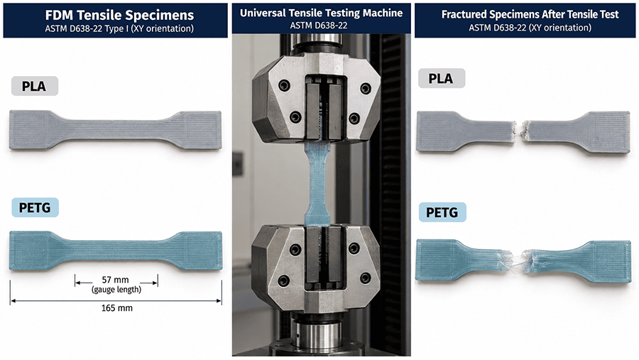
For a meaningful PETG vs PLA tensile strength comparison, ASTM D638-22 provides a common testing method. Specimen geometry, conditioning, test speed, strain measurement, and the reported strength definition must be consistent. FDM specimens also require documented build orientation, raster configuration, infill, and printing conditions.
In EPOC CRAFTER’s electronics bracket case EC-FDM-26-1008-P01, five XY tensile specimens were tested for each formulation. The specimens were conditioned for 48 hours at 23 ± 2°C and 50 ± 10% relative humidity. Testing used ASTM D638-22 Type I specimens, a 5 mm/min crosshead speed, and a nominal 50 mm extensometer gauge length.
| ASTM D638-22 result | PLA | PETG |
| Tensile strength, mean ± sample SD | 46.22 ± 0.66 MPa | 36.18 ± 0.46 MPa |
| Tensile modulus, mean ± sample SD | 2.912 ± 0.043 GPa | 1.970 ± 0.036 GPa |
| Elongation at break, mean ± sample SD | 3.62 ± 0.19% | 8.58 ± 0.35% |
| Specimens tested | 5 | 5 |
Under these conditions, PLA had higher tensile strength and stiffness. PETG showed greater elongation before fracture.
This tensile test does not establish impact toughness. Elongation at break and impact resistance are different properties, and no comparative impact test was recorded for this case.
3.2. Layer Bonding, Print Orientation and Impact Behavior
A tensile specimen loaded along its printed XY direction does not measure the same failure mechanism as a specimen pulled across its deposited layers.
In FDM printing, adjacent roads and successive layers must fuse during deposition. Extrusion temperature, deposited-road contact, cooling, filament condition, and build orientation influence the resulting bond quality.
This makes part orientation an engineering decision, particularly where a mounting boss, snap feature, or bracket flange could experience tension across layer interfaces.
The EC-FDM-26-1008-P01 tensile specimens were loaded along their XY axes. No Z-oriented tensile results or direct interlayer bond strength measurements were recorded. The XY results therefore cannot be used to rank PLA and PETG for loading perpendicular to the deposited layers.
Likewise, higher elongation does not guarantee greater impact resistance in a finished bracket. Impact behavior depends on material formulation, notch geometry, loading rate, temperature, and the location of printed features.
For functional parts, identify the likely failure direction before selecting a material or orienting the build. A bracket that passes an XY tensile test may still require separate verification around bolt holes, ribs, and layer interfaces.
3.3. Strength Versus Functional Deflection
Higher tensile strength does not automatically mean better dimensional stability under every service condition.
In the same EPOC CRAFTER bracket case, finished parts were subjected to a 25 N proof load for 60 seconds at 23°C. The acceptance limits were 1.0 mm maximum peak deflection and 0.20 mm maximum residual deflection after 10 minutes.
| Functional test | PLA | PETG |
| Peak deflection | 0.61 to 0.66 mm | 0.79 to 0.84 mm |
| Residual deflection after 10 minutes | 0.04 to 0.06 mm | 0.09 to 0.12 mm |
| Proof-load acceptance | 5 of 5 passed | 5 of 5 passed |
PLA deflected less under the recorded room-temperature load, consistent with the higher stiffness measured in its XY tensile specimens. Both materials met the specified proof-load acceptance limits.
The material choice changed when the brackets were evaluated at elevated temperature, where PETG met the required mounting-hole positional stability and PLA did not. That thermal comparison is addressed in the next section.
For mechanical design, keep three questions separate: how much load the material can resist, how far the part deflects, and whether its critical features remain within tolerance after loading.
4. PETG vs PLA Heat Resistance: HDT, Tg and Service Temperature
PETG often resists heat-related deformation better than conventional PLA, but a filament’s advertised heat resistance does not tell you how a finished part will behave under load.
For functional components, the relevant question is whether critical dimensions and mechanical connections remain acceptable at the expected operating temperature.
4.1. HDT Is Not the Same as Tg or Continuous Service Temperature
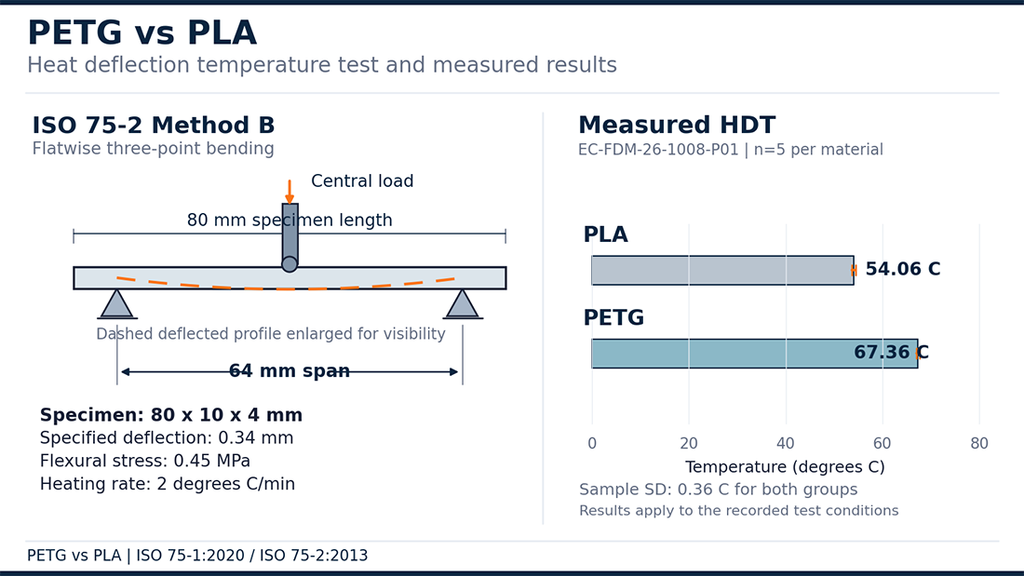
Heat deflection temperature (HDT) measures the temperature at which a plastic specimen reaches a specified deflection while subjected to a defined bending stress and heating rate.
Glass transition temperature (Tg) describes a change in the molecular mobility of the amorphous phase. It is not a loaded-part deformation limit. Melting temperature (Tm), where applicable, describes a different thermal transition.
None of these values independently establishes a safe continuous operating temperature.
ISO 75-1:2020 defines the general HDT test principles. For unfilled plastics, the applicable specimen requirements and specific test conditions must also be established under ISO 75-2.
An HDT comparison is meaningful only when the test method, bending stress, specimen geometry, preparation, conditioning, and heating conditions are identified. Differences in initial flexural modulus also affect how results should be interpreted.
4.2. Measured HDT: PLA and PETG Under the Same Test Conditions
EPOC CRAFTER tested five HDT specimens from each material in case EC-FDM-26-1008-P01.
Both groups used the following conditions:
| Test parameter | Recorded condition |
| Test method | ISO 75-1:2020 and ISO 75-2:2013, Method B |
| Flexural stress | 0.45 MPa |
| Loading configuration | Flatwise three-point bending |
| Specimen dimensions | 80 × 10 × 4 mm |
| Support span | 64 mm |
| Heating rate | 2°C/min |
| Specified deflection | 0.34 mm |
| Conditioning | 48 h at 23 ± 2°C and 50 ± 10% RH |
| Specimens per material | 5 |
The measured results were:
| HDT result | PLA | PETG |
| Mean HDT | 54.06°C | 67.36°C |
| Sample standard deviation | 0.36°C | 0.36°C |
PETG reached the specified deflection temperature 13.30°C later than PLA under these recorded test conditions.
That difference supports a comparison of the two tested formulations. It does not establish a universal 13.30°C heat-resistance advantage for PETG or prove that either material can sustain continuous loading at its measured HDT.
4.3. The 55°C Bracket Test Determined Material Selection
The electronics mounting bracket also underwent a separate functional test at 55°C for one hour under a 4.1 N load.
The allowable mounting-hole center drift was 0.30 mm.
PLA produced 0.32 to 0.37 mm drift, exceeding the requirement in all five parts. PETG produced 0.17 to 0.21 mm drift, meeting the requirement in all five parts.
This was the decisive thermal performance result for the bracket. The selected PETG formulation maintained acceptable mounting geometry under the recorded short-duration exposure.
The HDT test helped explain the difference in thermal response, but the finished-part test established which candidate met the specified assembly requirement.
Neither test verifies the intended 24-month service life, long-term creep resistance, or performance at temperatures above 55°C. Those requirements need separate qualification before they can be claimed.
5. PETG vs PLA: Moisture, Water Resistance and Environmental Exposure
Moisture affects PETG and PLA in two different ways. Water absorbed by filament before printing can interfere with extrusion and material quality. Water exposure after printing raises a separate question: whether the finished part retains its dimensions and mechanical performance in service.
Neither property can be judged from the filament name alone.
5.1. Filament Moisture and Drying Before Printing
Both PLA and PETG require appropriate storage and moisture control. Wet filament can produce bubbles, inconsistent extrusion, poor surface finish, or changes in mechanical performance. The severity depends on the formulation, moisture level, processing temperature, and exposure history.
ISO/ASTM 52903-1:2020 addresses feedstock identification, packaging, storage recommendations, and quality consistency for material extrusion additive manufacturing. It does not prescribe one universal drying temperature, drying duration, or acceptable moisture content for all PLA and PETG filaments.
For production work, follow the specific filament manufacturer’s drying instructions and record the material condition before printing.
EPOC CRAFTER documented the following preparation conditions for case EC-FDM-26-1008-P01:
| Recorded condition | PLA | PETG |
| Storage temperature | 22°C | 22°C |
| Storage relative humidity | 35% RH | 35% RH |
| Packaging | Sealed with desiccant | Sealed |
| Drying temperature | 45°C | 65°C |
| Drying duration | 4 hours | 6 hours |
| Measured filament moisture content | Not measured | Not measured |
These are the drying conditions used for the tested filament lots, not general drying recommendations for other products.
The recorded process establishes how the material was prepared. It does not establish the initial moisture content, the final moisture content, or whether one filament absorbed more water than the other.
5.2. Water Resistance of Finished PETG and PLA Parts
PETG is often considered for parts exposed to occasional moisture, but neither PETG nor PLA should be described as universally waterproof.
A finished FDM part contains deposited roads, layer interfaces, and possible internal voids. Its resistance to liquid ingress depends on wall construction, extrusion quality, geometry, and any sealing treatment. Material resistance to water and the ability of a printed enclosure to prevent leakage are different requirements.
For an electronics enclosure, confirm whether the specification calls for resistance to humidity, splashes, condensation, or liquid immersion. Each condition presents a different validation problem.
Water exposure may also affect dimensions or mechanical performance over time. A useful comparison requires the actual filament grades, defined exposure conditions, and measurements before and after exposure.
5.3. Outdoor Exposure and Chemical Resistance
Choosing PETG over PLA does not automatically qualify a printed part for outdoor service.
Ultraviolet exposure, temperature cycling, rain, and sustained loading can affect polymer components. UV stabilizers, pigments, fillers, and the specific resin formulation can change the outcome. A material described as PETG may therefore perform differently from another PETG grade in the same environment.
Chemical resistance also requires a defined exposure. Contact with cleaning agents, oils, fuels, or solvents cannot be assessed reliably from a generic PLA or PETG label.
For outdoor housings or industrial fixtures, obtain grade-specific environmental data and verify the finished geometry under the expected conditions.
The EPOC CRAFTER electronics bracket case was limited to indoor use without direct UV exposure or chemical washing. Its recorded tests do not establish water ingress resistance, outdoor durability, or chemical compatibility.
For that bracket, the documented material selection rests on mechanical and short-duration thermal verification, not on an untested environmental advantage.
6. PETG vs PLA: Printability, Warping and Dimensional Accuracy
PLA is generally easier to print than PETG, particularly when controlling stringing and maintaining surface quality. PETG often needs different extrusion and cooling settings. Neither material, however, guarantees better dimensional accuracy.
For engineering parts, printability is not just about completing a successful build. Mounting holes, locating features, mating surfaces, and wall dimensions must remain within the specified limits.
6.1. PETG vs PLA Print Settings
PLA and PETG require printing conditions matched to their individual formulations. Nozzle temperature, bed temperature, cooling, print speed, and extrusion flow affect deposition quality and interlayer bonding.
In EPOC CRAFTER case EC-FDM-26-1008-P01, both materials were printed on a Bambu Lab X1 Carbon with a 0.4 mm hardened-steel nozzle and a smooth PEI build plate.
| FDM parameter | PLA | PETG |
| Nozzle temperature | 215°C | 245°C |
| Bed temperature | 60°C | 75°C |
| Observed chamber temperature | 28 to 32°C | 30 to 35°C |
| Layer height | 0.20 mm | 0.20 mm |
| Extrusion line width | 0.44 mm | 0.44 mm |
| External wall speed | 40 mm/s | 40 mm/s |
| Internal print speed | 70 mm/s | 70 mm/s |
| Part cooling | 80 to 100% | 25 to 40% |
| Wall count | 4 perimeters | 4 perimeters |
| Infill | 40% gyroid | 40% gyroid |
| Build orientation | Flat, XY plane | Flat, XY plane |
These settings describe the actual builds. They are not universal PETG or PLA printing recommendations.
The same geometry, layer height, wall count, and infill were retained to support the comparison. Extrusion temperatures and cooling differed because each filament required its own processing conditions.
The brackets were manufactured in one build per material. The recorded results therefore describe those builds and do not establish long-term machine or batch repeatability.
6.2. Stringing, Warping and Surface Quality
PETG can produce fine strings between separated features when molten material continues to flow during nonprinting movements. Retraction, temperature, travel motion, and filament condition can affect the result.
Warping occurs when nonuniform cooling and contraction cause a printed region to move away from its intended geometry. Bed adhesion, thermal conditions, part geometry, and deposition strategy all matter.
PLA generally presents fewer stringing challenges, but poor adhesion, excessive cooling, or unsuitable geometry can still produce defects.
For PETG, reducing stringing by changing retraction or temperature should not come at the expense of inadequate material deposition or poor layer bonding. Adjustments need to be checked against the finished part, not just surface appearance.
The electronics bracket case does not include quantitative stringing, warpage, or surface roughness measurements. No comparative defect rate can be established from the recorded data.
6.3. Dimensional Accuracy and Critical Feature Inspection
Printed bracket geometry follows the DFM design guidelines, while dimensional tolerances and inspection standards determine the acceptance checks.
A nominal filament diameter does not determine the final dimensional accuracy of a printed component.
In the case study, both filaments had a nominal diameter of 1.75 mm. Incoming five-point micrometer measurements ranged from 1.74 to 1.76 mm for each material.
The assumed supplier tolerance was ±0.05 mm, but this was not confirmed against a manufacturer specification.
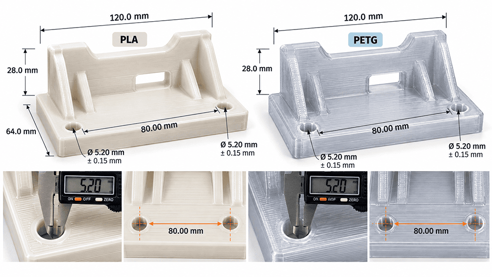
The finished brackets had two M5 clearance holes and an 80.00 mm nominal center distance. Five parts from each material were inspected.
| Critical feature | Drawing requirement | PLA measured range | PETG measured range |
| Mounting-hole diameter | Ø5.20 ± 0.15 mm | 5.17 to 5.21 mm | 5.20 to 5.23 mm |
| Hole-center distance | 80.00 ± 0.20 mm | 80.03 to 80.07 mm | 80.05 to 80.09 mm |
| Parts meeting both recorded dimensional limits | Required | 5 of 5 | 5 of 5 |
Hole diameters were checked using pin gauges or bore gauges, while the hole-center distances were measured using a coordinate measuring machine.
Both materials met the two recorded dimensional requirements after printing. Neither group required hole reaming.
PETG showed slightly larger measured hole-center distances in this batch, but the differences do not establish that PLA is inherently more dimensionally accurate. The results cover two features, five parts per material, and one recorded build condition for each material.
Dimensional acceptance at room temperature also did not guarantee equivalent performance after thermal exposure. As shown in Section 4, the PLA brackets exceeded the specified hole-center drift at 55°C, while PETG remained within the acceptance limit.
A production drawing should identify which features require inspection, how they are measured, and whether the acceptance condition applies immediately after printing or after environmental exposure.
7. PETG vs PLA: Which Material Fits Your Part?
Choose PLA or PETG according to the feature most likely to limit the part’s performance. For a rigid prototype, that might be deflection under load. For an electronics mounting bracket, it could be hole alignment after heating. An exposed enclosure may instead require impact, moisture, or environmental testing.
The part’s function matters more than a generic filament strength ranking.
7.1. Material Selection by Application
The FDM 3D printing capability page describes the process route available for functional printed parts.
| Application | Initial material choice | Engineering reason and verification |
| Visual prototypes and fit-check models | PLA | Generally straightforward printing and good rigidity. Check mating dimensions and surface requirements. |
| Indoor positioning fixtures | PLA | Suitable to consider where temperature and loads are controlled. Verify deflection, attachment features, and repeated use. |
| Electronic enclosures and protective covers | PLA or PETG | Select according to internal temperatures, impact exposure, mounting features, and dimensional requirements. |
| Loaded mounting brackets | Application dependent | Check tensile loading direction, local stress around fasteners, stiffness, and service temperature. |
| Parts requiring greater deformation before fracture | PETG | A candidate where ductility matters. Verify the actual grade and printed feature rather than relying on elongation alone. |
| Parts exposed to intermittent elevated temperatures | PETG | Often worth testing before conventional PLA. Confirm loaded dimensional stability at the required temperature. |
| Outdoor fixtures and housings | Grade dependent | Verify UV stability, weathering, temperature cycling, and moisture exposure. Neither generic filament name qualifies the part. |
These are starting points for material selection, not automatic design approvals.
For an electronics product, the enclosure body and its mounting features may have different failure risks. A cover might need impact resistance, while its screw bosses or locating ribs may be limited by local stresses or heat-induced movement.
7.2. Real Production Case: Why PETG Was Selected for an Electronics Bracket
The consumer electronics manufacturing context makes the mounting interface and retained fit more important than a generic strength ranking.
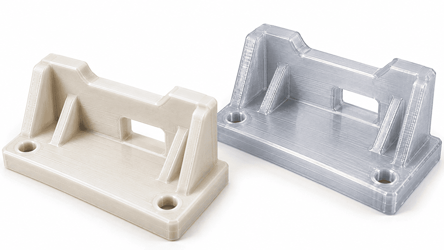
In EPOC CRAFTER production case EC-FDM-26-1008-P01, the component was a 120 × 64 × 28 mm electronics mounting bracket with a 3.2 mm nominal wall thickness, two M5 clearance holes, and two locating ribs.
It supported a 0.42 kg control module through a bolted, two-point mounting arrangement.
The bracket needed to satisfy three practical requirements:
- Maintain the specified mounting-hole dimensions.
- Withstand a 25 N proof load without cracking or exceeding the permitted deflection.
- Keep mounting-hole center drift within 0.30 mm during a one-hour exposure at 55°C under a 4.1 N load.
Both materials met the recorded room-temperature dimensional limits and proof-load requirements. PLA also showed higher XY tensile strength and tensile modulus.
The difference appeared during the heated assembly test. All five PETG brackets stayed within the allowed hole-center drift, while all five PLA brackets exceeded it.
PETG was therefore selected for this bracket.
The result illustrates a specific engineering decision: greater tensile strength did not compensate for failure to meet the critical assembly dimension at the required temperature.
The approval applies to the tested material references, geometry, build conditions, and short-duration acceptance tests. The intended 24-month service life, long-term creep response, and Z-direction performance remain separate qualification requirements.
7.3. When Neither Material Should Be Approved Without Further Testing
Rapid prototyping for material validation lets the team examine critical fit and temperature response before specifying production tooling or volume.
Neither PLA nor PETG should be selected solely from a comparison chart when the part has demanding operating conditions.
A loaded bracket near a heat source requires verification of dimensional movement and time-dependent deformation. A snap feature needs repeated assembly testing and attention to print orientation. An outdoor enclosure needs grade-specific weathering evidence. A chemically exposed fixture requires compatibility testing with the actual cleaning or process fluids.
A passed short-duration proof-load test does not establish fatigue life or creep resistance.
8. PETG vs PLA: Material Verification and Procurement Checklist
Selecting PETG or PLA is only the beginning of a production decision. The purchase specification must identify the actual filament, and the inspection plan must verify the features that matter to the assembly.
A supplier’s material data sheet can support initial screening, but it does not establish the mechanical or dimensional performance of your finished FDM part.
8.1. What to Specify in a PETG or PLA RFQ
For a functional 3D printed component, include the following information in the RFQ and technical documentation.
| Verification item | Required information | Why it matters |
| Material identity | Polymer type, manufacturer, exact filament grade, additives and fillers | Prevents substitution between formulations with different properties |
| Feedstock traceability | Lot number, relevant material documentation, manufacturing information | Connects incoming material to production and inspection results |
| Filament specification | Nominal diameter, supplier tolerance, applicable inspection requirements | Supports consistent feeding and extrusion |
| Build requirements | Orientation, layer height, perimeter count, infill specification, and controlled process settings | Defines the printed structure being evaluated |
| Mechanical verification | Applicable test method, specimen orientation, loading conditions, and acceptance criteria | Makes reported strength and deformation results interpretable |
| Thermal verification | Test standard, applied stress, specimen condition, exposure temperature, and duration | Separates standardized material tests from actual service requirements |
| Critical dimensions | Drawing tolerances, inspection method, and measurement conditions | Establishes whether the part fits its mating assembly |
| Environmental exposure | Moisture, UV, chemicals, temperature cycling, and service duration, where applicable | Identifies conditions requiring additional qualification |
ISO/ASTM 52903-1:2020 provides a basis for material extrusion feedstock identification, quality consistency, packaging, storage, and traceability. It does not establish a universal acceptance specification for every PLA or PETG printed part.
The drawing, purchase order, and agreed verification plan must define the additional requirements.
8.2. Incoming Filament and Finished-Part Inspection
Incoming inspection should confirm that the delivered filament matches the approved material specification. Record its identification, lot, packaging condition, and relevant dimensions.
For the finished part, measure the features most likely to cause assembly failure. A mounting-hole diameter, locating feature, or critical center distance may matter more than the overall appearance.
The EPOC CRAFTER electronics bracket case provides a practical example. Both material groups met their room-temperature hole-diameter and center-distance tolerances. That result alone was insufficient for material approval because the assembly also required dimensional stability during a one-hour exposure at 55°C.
The heated fit test identified the decisive difference.
This is why inspection requirements should distinguish dimensions measured after printing from dimensions that must remain acceptable under operating conditions.
8.3. Production Release and Material Substitution
Low volume production qualification should carry the approved filament identity, build configuration and inspection requirements into each release.
Before production release, confirm that the approved material grade, lot documentation, print configuration, and inspection records match the qualified process.
A change in filament manufacturer, formulation, build orientation, or critical processing conditions may require additional verification. The necessary scope depends on the affected property and the part’s failure risk.
For case EC-FDM-26-1008-P01, PETG was selected based on the recorded mechanical, thermal, and dimensional acceptance results. Commercial grade identification, supporting supplier documentation, and the remaining service-life qualification requirements must still be resolved before the applicable production release.
Do not transfer the bracket’s acceptance results to another part geometry or PETG formulation without checking the relevant conditions.
9. PETG vs PLA: Frequently Asked Questions
9.1. Is PETG Stronger Than PLA?
Not necessarily. PLA can have higher tensile strength and stiffness, while PETG may exhibit greater elongation before fracture. The result depends on the specific filament grade, print orientation, specimen geometry, and testing conditions. Compare tensile strength, impact resistance, and layer bonding separately rather than treating them as one property.
9.2. Is PETG Better Than PLA for Functional Parts?
PETG is often worth considering for parts requiring greater ductility or resistance to short-term heat exposure. PLA remains a practical option for rigid, lightly loaded components in controlled conditions. Neither material should be approved without checking the actual load, temperature, critical dimensions, and expected failure mode.
9.3. Is PETG More Heat Resistant Than PLA?
Many conventional PETG formulations show higher heat deflection temperatures than standard PLA formulations, but this is not universal. Compare HDT values obtained at the same bending stress and under equivalent test conditions. HDT does not establish a safe continuous service temperature.
9.4. Does PETG Absorb More Moisture Than PLA?
There is no reliable universal ranking for every PLA and PETG filament formulation. Moisture uptake depends on material composition, exposure conditions, and time. Follow the manufacturer’s drying and storage requirements rather than assuming one drying procedure applies to all products.
9.5. Is PETG More Difficult to Print Than PLA?
PETG generally requires closer control of extrusion temperature, cooling, and retraction to manage stringing and surface quality. PLA is usually easier to print, but either material can produce poor results when the filament condition or process settings are unsuitable.
9.6. Can PLA or PETG Be Used for Outdoor Parts?
Both require grade-specific evaluation before outdoor use. PETG may be a candidate for certain outdoor applications, but UV stability, weathering, thermal cycling, and mechanical loading must be checked. A generic PETG label does not establish outdoor durability.
9.7. Which Has Better Dimensional Accuracy, PETG or PLA?
Neither material guarantees better dimensional accuracy. Part geometry, printer calibration, extrusion flow, cooling, and build orientation influence the finished dimensions. Inspect the critical features against the drawing and verify their stability under relevant service conditions.
10. PETG or PLA: Final Material Decision
PLA is a strong candidate for rigid prototypes and indoor parts where printing simplicity and stiffness matter. PETG deserves closer consideration when ductility, impact exposure, or short-term thermal deformation could determine whether a part passes inspection.
For the EPOC CRAFTER electronics bracket, PLA delivered higher XY tensile strength and stiffness, but PETG met the critical mounting-hole drift requirement at 55°C. That requirement determined the material choice.
Before approving either filament for production, identify the exact grade, control the print process, and test the finished part against its operating loads, temperature exposure, and critical dimensions. A material comparison is useful for screening. The part’s acceptance results should drive the final decision.
Ready to Quote Your CNC Prototype?
Upload your STEP file and get a DFM review + quote within 12 hours.
No tooling cost. Minimum 1 part.
