

Dewey Wu General Manager & senior mechanical engineer at EPOC CRAFTER, 15 years in design engineering, quality, and metallurgy. Hands-on across CNC machining, metalwork, sheet metal, and prototyping (subtractive + 3D printing).
Sheet metal tolerances span ±0.05 mm on laser-cut linear dimensions to ±1.0° on press brake bend angles, with feature position accuracy dropping by a factor of five when holes or slots sit inside bend deformation zones. A hole placed at the recommended minimum distance of 2.5t + r from a bend centerline (t = material thickness, r = inside bend radius) holds position within ±0.10 mm. The same hole at 1.5t from the bend drifts past ±0.50 mm, adding a secondary machining step that raises unit cost 20 to 40%. ISO 2768-1:1989 medium class specifies ±0.2 mm for linear dimensions between 6 and 30 mm, and ±0°30′ for angles with a shorter edge between 10 and 50 mm. This guide covers ISO 2768-1 tolerance classes, process-specific tolerance tables, hole spacing and edge distance rules, material thickness tolerances for 1018 steel (ASTM A1008/A1008M-26), 304 stainless (ASTM A240/A240M), and 5052/6061 aluminum (ASTM B209/B209M-21a), and stack-up calculation for multi-bend parts.
1. What Sheet Metal Tolerances Cover
Sheet metal tolerances fall into three categories: linear dimensions (lengths, hole diameters, edge distances), angular dimensions (bend angles, flange angles), and feature positions (hole-to-hole spacing, hole-to-edge distance, hole-to-bend clearance). Each category responds to a different set of process and material variables. On parts with three or more bends, specifying linear tolerance to ±0.10 mm without verifying angular tolerance frequently produces parts that pass CMM inspection on individual features but fail assembly fit checks.
The Feature-First Tolerance Method starts with the tightest-tolerance feature on your part, checks its relationship to bends and edges, selects the tolerance class your function requires, and verifies process capability before committing the drawing. For a complete set of sheet metal DFM design guidelines, the design guide companion covers the full rule framework.
Engineering note: On a 1.5 mm 304 stainless bracket, switching from air bending (±0.5°) to bottom bending (±0.25°) cuts angular deviation in half, but bottom bending requires 3 to 5 times more press force and dedicated tooling. For prototypes under 50 pieces, air bending at ±0.5° is the cost-effective baseline.
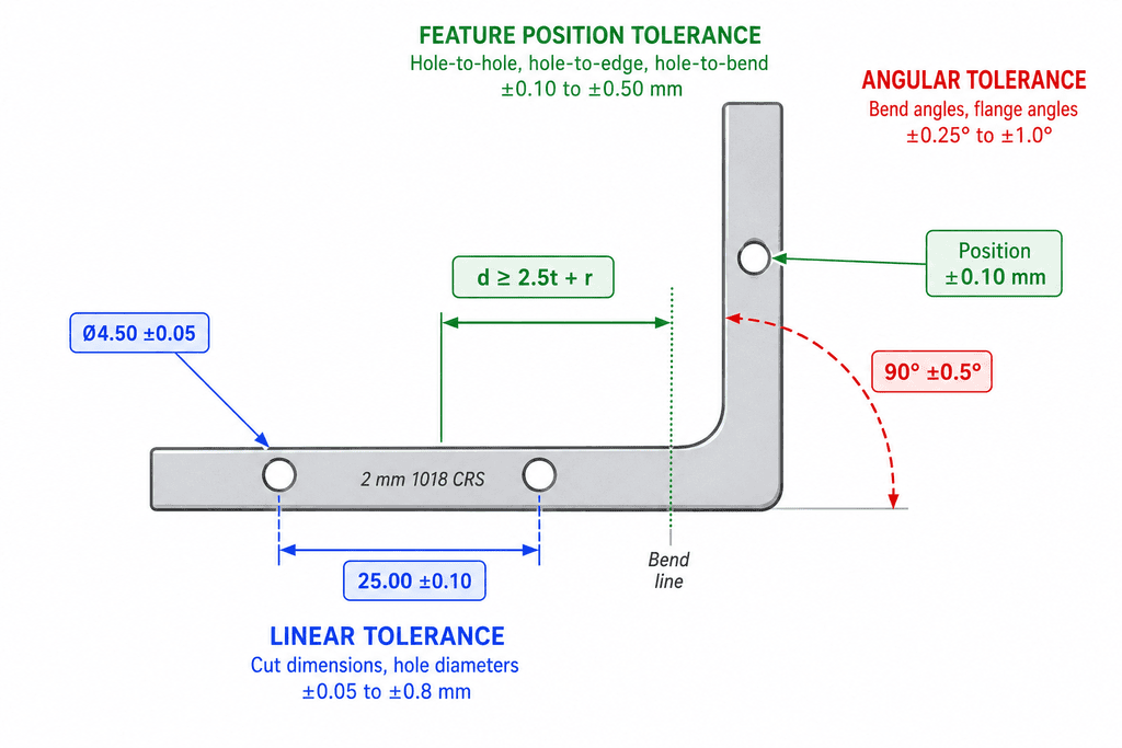
Table: Tolerance Category Overview
| Linear | Cut dimensions, hole diameters, edge distances | ±0.05 to ±0.8 mm | Cutting method (laser, punch, waterjet) |
| Angular | Bend angles, flange angles | ±0.25° to ±1.0° | Forming method (air bend, bottom bend, coining) |
| Feature position | Hole-to-hole, hole-to-edge, hole-to-bend | ±0.10 to ±0.50 mm | Feature placement relative to bends and edges |
2. ISO 2768-1 Tolerance Classes for Sheet Metal Parts
ISO 2768-1:1989 assigns four general tolerance classes to linear and angular dimensions that carry no individual callout on the drawing: fine (f), medium (m), coarse (c), and very coarse (v). Medium (m) is the default for sheet metal fabrication. Coarse (c) matches the natural capability of CNC press brake air bending. The standard remains current as of 2026.
2.1 Linear Dimension Tolerances
Table: ISO 2768-1 Permissible Deviations for Linear Dimensions (mm)
| f (fine) | ±0.05 | ±0.05 | ±0.1 | ±0.15 | ±0.2 | ±0.3 | ±0.5 | N/A |
| m (medium) | ±0.1 | ±0.1 | ±0.2 | ±0.3 | ±0.5 | ±0.8 | ±1.2 | ±2 |
| c (coarse) | ±0.2 | ±0.3 | ±0.5 | ±0.8 | ±1.2 | ±2 | ±3 | ±4 |
| v (very coarse) | N/A | ±0.5 | ±1 | ±1.5 | ±2.5 | ±4 | ±6 | ±8 |
Source: ISO 2768-1:1989, Table 1. Confirmed current as of August 2026.
For a 50 mm hole-to-hole spacing on a laser-cut 1.5 mm 5052-H32 aluminum bracket, medium class allows ±0.3 mm. Fiber laser cutting holds ±0.10 mm on that dimension before the part reaches the press brake. The gap between ±0.10 mm cutting capability and ±0.3 mm drawing tolerance absorbs bending-induced position shift downstream.
2.2 Angular Dimension Tolerances
Table: ISO 2768-1 Permissible Deviations for Angular Dimensions
| f (fine) | ±1° | ±0°30′ | ±0°20′ | ±0°10′ | ±0°5′ |
| m (medium) | ±1° | ±0°30′ | ±0°20′ | ±0°10′ | ±0°5′ |
| c (coarse) | ±1°30′ | ±1° | ±0°30′ | ±0°15′ | ±0°10′ |
| v (very coarse) | ±3° | ±2° | ±1° | ±0°30′ | ±0°20′ |
Source: ISO 2768-1:1989, Table 2.
Air bending holds ±0.5° under production conditions. Medium class allows ±0°30′ (±0.5°) for flanges with a shorter side between 10 and 50 mm, but only ±0°20′ (±0.33°) for 50 to 120 mm. A 60 mm flange at ±0.33° exceeds air bending capability. Three options: switch to coarse class (±0°30′ for 50 to 120 mm flanges), add individual angular callouts (90° ±0.5°) on specific bends, or specify bottom bending at 3 to 5 times higher press force.
2.3 Specifying ISO 2768-1 on Your Drawing
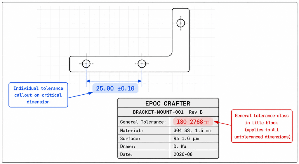
Place the notation in the title block: ISO 2768-m for medium class, ISO 2768-c for coarse. Only dimensions requiring tighter or looser control get individual callouts.
2.4 ISO 22081 and Geometric Tolerances
ISO 22081:2021 replaced ISO 2768-2:1989 for geometric tolerances (flatness, perpendicularity, symmetry, and similar GD&T controls). ISO 22081 does not provide default H/K/L tolerance grades. It requires you to declare a specific surface profile tolerance value with a datum system. For sheet metal drawings in 2026, specify ISO 2768-1 for linear and angular tolerances and add explicit geometric callouts per ISO 1101 on functional surfaces (flatness 0.3 mm on sealing surfaces, perpendicularity 0.5° on mounting flanges).
Table: ISO 2768-1 Class Selection Guide for Sheet Metal
| f (fine) | Precision flat parts, no bends | Flanges ≤10 mm only (±1°) | +15 to 25% |
| m (medium) | General sheet metal, 1 to 2 bends | Flanges ≤50 mm with air bending (±0.5°) | Baseline |
| c (coarse) | Multi-bend enclosures, 3+ bends | Flanges ≤120 mm with air bending | Comparable or lower |
| v (very coarse) | Large panels, HVAC ductwork | All forming processes | Lowest cost |
3. Tolerances by Cutting and Forming Process
Cutting process sets the tolerance floor on the flat blank. Forming adds deviation on top. The interaction between these two stages is where most tolerance problems start.
3.1 Cutting Process Tolerances
Table: Cutting Process Tolerance Comparison
| Fiber laser | ±0.05 to ±0.10 mm | ±0.10 mm | 0.15 to 0.30 mm | Ra 1.6 to 3.2 µm | Precision profiles, complex contours |
| CNC turret punch | ±0.10 to ±0.25 mm | ±0.15 mm | N/A (shear) | Ra 1.6 µm | High-volume hole patterns, louvers |
| Waterjet | ±0.10 to ±0.15 mm | ±0.15 mm | 0.8 to 1.2 mm | Ra 3.2 to 6.3 µm | Heat-sensitive materials, thick plate |
| Plasma | ±0.5 to ±1.5 mm | ±0.50 mm | 2.0 to 4.0 mm | Ra 6.3 to 12.5 µm | Structural plate, non-critical profiles |
3.2 Forming Process Tolerances
Table: Forming Process Tolerance Comparison
| Air bending | ±0.5° to ±1.0° | ±0.15 to ±0.25 mm | 1x (baseline) | Prototypes, short runs |
| Bottom bending | ±0.25° to ±0.5° | ±0.10 to ±0.15 mm | 3 to 5x | Production angular control |
| Coining | ±0.1° to ±0.25° | ±0.05 to ±0.10 mm | 5 to 10x | Sealing surfaces, optical mounts |
Springback on 304 stainless steel (ASTM A240/A240M, YS ≥205 MPa) ranges from 2° to 5° per bend. On 5052-H32 aluminum (YS ≥160 MPa per ASTM B209/B209M-21a), springback drops to 1° to 2°, making angular tolerance easier to hold.
According to Dewey Wu, General Manager and Senior Mechanical Engineer at EPOC CRAFTER, “Laser positioning accuracy of ±0.03 mm means nothing if your fixture allows 0.15 mm of part shift during bending. On a production run of 200 brackets in 1.2 mm 304 stainless, we measured ±0.08 mm on laser-cut hole positions before forming, and ±0.22 mm on the same holes after two bends. Eighty percent of the deviation came from fixture compliance, not the press brake itself. Switching from manual back-gauge positioning to CNC-controlled side clamps cut post-bend hole position error to ±0.12 mm without changing any other process parameter.”
A hole-to-hole dimension on one flat panel carries only cutting tolerance (±0.10 mm). The same dimension across a 90° bend reaches ±0.30 to ±0.50 mm. For bend radius and K-factor calculations, the K-factor guide covers how flat-pattern dimensions translate to formed-part dimensions.
EPOC CRAFTER capability: fiber laser ±0.05 mm (sheet under 3 mm), CNC punch ±0.10 mm hole position, air bending ±0.5°, bottom bending ±0.25°. Request a DFM review through our sheet metal fabrication page.
4. Hole Spacing, Edge Distance, and Feature Design Rules
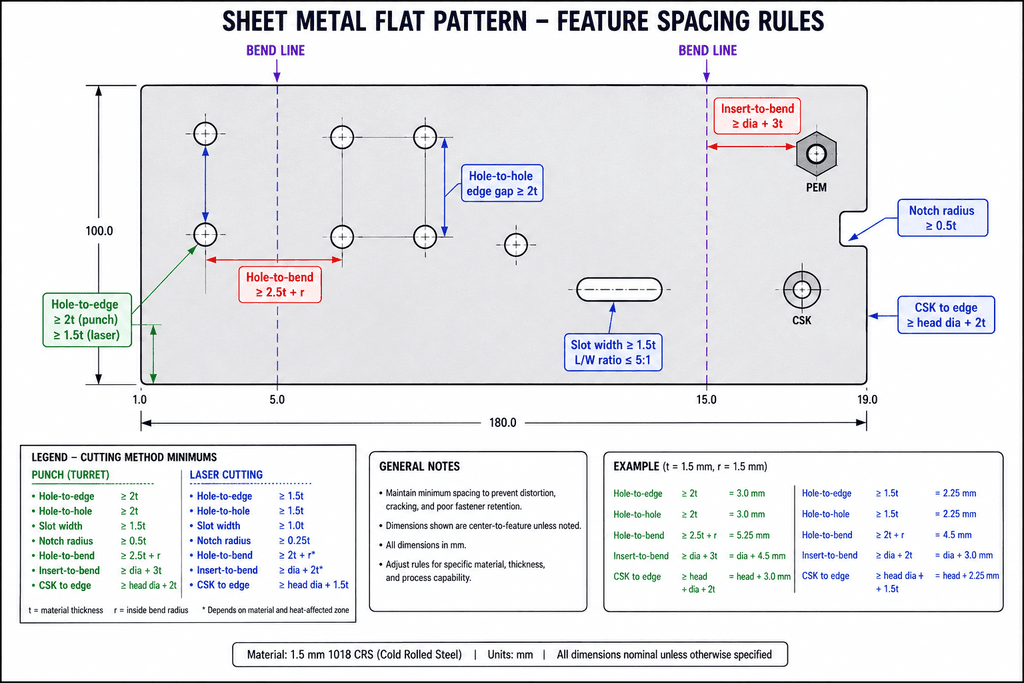
Seven feature placement rules prevent the majority of deformation, tearing, and position errors on formed sheet metal parts. Each rule ties feature geometry to material thickness (t) and inside bend radius (r). Violating any rule forces secondary operations that add 20 to 40% to unit cost and 2 to 5 days to lead time.
4.1 Minimum Hole Diameter
Punched holes: diameter ≥ 1.0t. Laser-cut holes: down to 0.5t on thin gauges, but hole wall quality degrades above 3 mm thickness where kerf taper affects roundness by 0.05 to 0.10 mm. Recommended minimum across both processes: ≥ 1.5t.
4.2 Hole-to-Hole Spacing
Maintain ≥ 2t of solid material between adjacent hole edges. On a 1.5 mm sheet, two M4 clearance holes (4.5 mm diameter) need center-to-center ≥ 7.5 mm. Spacing below 2t causes stress zone overlap, producing out-of-round holes that reject during fastener fit checks.
4.3 Hole-to-Edge Distance
Laser-cut parts: ≥ 1.5t from hole edge to part edge. Punched parts: ≥ 2t (shearing force pushes material outward). Specifying 2t as the default covers both processes.
4.4 Hole-to-Bend Distance
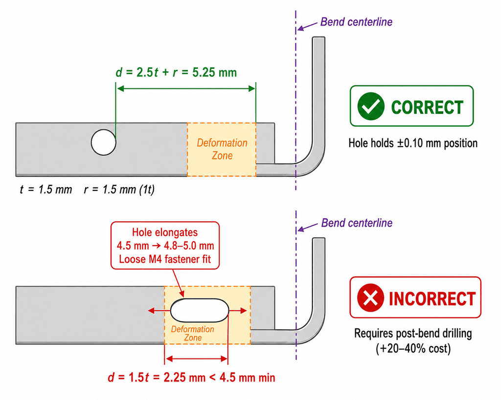
The deformation zone extends 1t to 2t from the bend centerline. The minimum distance from hole edge to bend tangent line:
d = 2t + r (minimum) | d = 2.5t + r (recommended)
For a 1.5 mm sheet with 1.5 mm inside bend radius: minimum 4.5 mm, recommended 5.25 mm. A 4.5 mm M4 clearance hole inside the deformation zone elongates to 4.8 to 5.0 mm, causing loose fastener fit. When a hole must sit closer than 2t + r, cut the hole after forming with the part fixtured in its bent state (holds ±0.10 mm, adds one operation).
4.5 Slot and Notch Rules
Minimum slot width: ≥ 1.5t (laser), ≥ 2t (punch). Length-to-width ratio ≤ 5:1 without radius ends. Notch internal corner radius ≥ 0.5t to prevent fatigue cracking.
4.6 Tab and Bend Relief Sizing
Tab minimum width: 2t, minimum length: 4t. Bend relief width ≥ t, depth ≥ t + r or 1 mm past the bend tangent, whichever is greater.
4.7 Countersink and Hardware Insert Clearance
Countersink to nearest edge: ≥ head diameter + 2t. Press-fit insert to nearest bend: ≥ insert diameter + 3t. Install inserts after bending when placement is within 3t + r of any bend.
Table: Feature Design Rules Summary
| Hole diameter (punched) | ≥ 1.0t | ≥ 1.5t | Punch pin breakage, rough hole wall |
| Hole diameter (laser) | ≥ 0.5t | ≥ 1.0t | Kerf taper, out-of-round on thick stock |
| Hole-to-hole (edge gap) | ≥ 2t | ≥ 2.5t | Hole deformation, web buckling |
| Hole-to-edge | ≥ 1.5t (laser), ≥ 2t (punch) | ≥ 2t | Edge bulge, tear-out |
| Hole-to-bend | ≥ 2t + r | ≥ 2.5t + r | Hole elongation, loose fastener fit |
| Slot width | ≥ 1.5t (laser), ≥ 2t (punch) | ≥ 2t | Slot wall roughness |
| Slot L/W ratio | ≤ 5:1 | ≤ 4:1 | Stress cracking under vibration |
| Notch radius | ≥ 0.5t | ≥ 1.0t | Fatigue crack initiation |
| Tab width | ≥ 2t | ≥ 3t | Root cracking during forming |
| Bend relief width | ≥ t | ≥ 1.5t | Tearing at bend intersection |
| Countersink to edge | ≥ head dia + 2t | ≥ head dia + 3t | Countersink breaks through edge |
| Insert to bend | ≥ insert dia + 3t | ≥ insert dia + 3t + r | Insert loosening, sheet cracking |
Engineering note: These rules apply to 0.5 to 6 mm sheet gauges. Below 0.5 mm, handling and fixturing dominate. Above 6 mm, verify hole-to-bend distance against actual bend radius for your material. For sheet metal material properties by alloy, the materials guide covers 5052, 6061, 304, 1018, and galvanized steel.
5. Material Thickness Tolerances
Every sheet arrives from the mill with thickness variation governed by ASTM or ANSI standards. That variation compounds with cutting and forming tolerances.
5.1 1018 Cold-Rolled Steel (ASTM A1008/A1008M-26 via A568/A568M)
Table: 1018 CRS Thickness Tolerances (width ≤1800 mm)
| ≤0.4 | +0.05 / -0 | ±0.025 |
| >0.4 to 1.0 | +0.08 / -0 | ±0.040 |
| >1.0 to 1.2 | +0.10 / -0 | ±0.050 |
| >1.2 to 2.5 | +0.12 / -0 | ±0.060 |
| >2.5 to 4.0 | +0.15 / -0 | ±0.075 |
Source: ASTM A568/A568M-25a, referenced by A1008/A1008M-26.
5.2 304 Stainless Steel (ASTM A240/A240M via A480/A480M)
Cold-rolled 304 sheet: ±0.04 mm at 0.5 mm gauge to ±0.15 mm at 3.0 mm per A480/A480M. Wider incoming thickness variation than 1018 CRS, combined with higher springback (YS ≥205 MPa), requires tighter press brake compensation.
5.3 5052-H32 and 6061-T6 Aluminum (ASTM B209/B209M-21a via ANSI H35.2)
Table: Aluminum Sheet Thickness Tolerances (width ≤914 mm)
| 1.0 mm | ±0.06 mm | ±0.05 mm |
| 1.6 mm | ±0.08 mm | ±0.05 mm |
| 2.0 mm | ±0.09 mm | ±0.06 mm |
| 3.2 mm | ±0.11 mm | ±0.09 mm |
| 4.0 mm | ±0.18 mm | ±0.15 mm |
Source: derived from ANSI H35.2-2024 (inch-to-mm conversion, rounded).
5.4 Cross-Material Comparison
Table: Thickness Tolerance at Typical Gauges (width ≤1000 mm)
| 1.0 mm | ±0.040 | ±0.04 to 0.05 | ±0.06 | ±0.05 |
| 2.0 mm | ±0.060 | ±0.08 to 0.10 | ±0.09 | ±0.06 |
| 3.0 mm | ±0.075 | ±0.10 to 0.15 | ±0.11 | ±0.09 |
Engineering note: On a 90° air bend in 2.0 mm 1018 with ±0.060 mm thickness variation, angular deviation from thickness alone is ±0.2° to ±0.3° (within ±0.5° air bending). On 304 stainless at ±0.10 mm variation plus higher springback, the angular contribution rises to ±0.4° to ±0.6°, pushing close to the ±0.5° limit. For 304 parts needing ±0.5° on bends, verify incoming thickness within ±0.06 mm or switch to bottom bending.
6. Tolerance Stack-Up Across Bends
A dimension crossing a bend line collects tolerance from four sources: cutting (±0.10 mm), bend angle deviation (±0.5° air bending), back-gauge position (±0.10 mm), and material thickness variation (±0.060 mm for 1018 CRS). Angular deviation of ±0.5° on a 30 mm flange produces ±0.26 mm of linear offset at the tip (30 × tan 0.5° = 0.26 mm).
Single-bend example (50 mm hole-to-hole crossing one bend on a 30 mm flange, 2 mm 1018 CRS):
Worst-case: ±0.10 + ±0.26 + ±0.10 + ±0.060 = ±0.52 mm
RSS: √(0.10² + 0.26² + 0.10² + 0.060²) = ±0.30 mm
ISO 2768-1 medium class allows ±0.3 mm for 30 to 120 mm. RSS sits at the limit; worst-case exceeds by 73%. Each additional bend adds another angular and back-gauge contributor. A U-channel crossing two bends reaches ±0.41 mm RSS, exceeding medium class. Switching to bottom bending (±0.25°, ±0.13 mm offset) cuts the two-bend RSS to ±0.25 mm, back inside medium class.
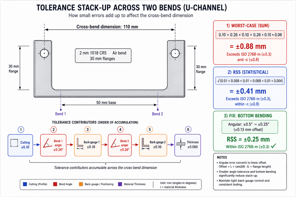
Table: Stack-Up Reduction Methods
| Bottom bending | 40 to 50% on angular contributor | 3 to 5x press force, dedicated die |
| Single-setup bending | 10 to 15% on total RSS | Compound tooling |
| Post-bend machining | Eliminates forming stack-up | Added operation, 2 to 5 day lead time |
| Datum unification | 15 to 25% on total RSS | Constrains bend sequence |
7. DFM Tolerance Checklist
Table: Sheet Metal Tolerance DFM Checklist
| 1 | General tolerance class declared | ISO 2768-m or -c in title block |
| 2 | Class matches process capability | ISO 2768-m for ≤2 bends; -c for 3+ |
| 3 | Hole diameter ≥ material thickness | Punched ≥ 1.0t; laser ≥ 0.5t |
| 4 | Hole-to-edge ≥ 2t | All holes |
| 5 | Hole-to-bend ≥ 2.5t + r | Hole edge to bend tangent |
| 6 | Hole-to-hole ≥ 2t edge gap | Adjacent hole edges |
| 7 | Cross-bend stack-up checked | RSS ≤ stated tolerance |
| 8 | Material thickness tolerance referenced | ASTM A568 / A480 / ANSI H35.2 |
| 9 | Individual callouts on critical features | ±value on tight-tolerance dims |
| 10 | Geometric tolerances on functional surfaces | Flatness, perpendicularity per ISO 1101 |
Catching a tolerance error at the drawing stage costs 15 minutes. The same error at first-article inspection costs a recut and 3 to 10 days. Request the downloadable checklist or send your STEP file for DFM review through our sheet metal fabrication capabilities page.
8.FAQ
Q1: What are standard tolerances for sheet metal fabrication?
Standard tolerances follow ISO 2768-1:1989 with four classes: fine (f), medium (m), coarse (c), and very coarse (v). Medium is the industry default. At medium class, 6 to 30 mm dimensions carry ±0.2 mm; 30 to 120 mm carry ±0.3 mm. Angular tolerance is ±0°30′ for flanges with shorter side between 10 and 50 mm. Process capability sets the floor: laser cutting holds ±0.05 to ±0.10 mm, CNC air bending holds ±0.5° to ±1.0°.
Q2: What is the minimum hole-to-bend distance in sheet metal?
Minimum distance from hole edge to bend tangent line is 2t + r, where t = material thickness and r = inside bend radius. Recommended: 2.5t + r. For 1.5 mm sheet with 1.5 mm bend radius: minimum 4.5 mm, recommended 5.25 mm. Holes closer than 2t + r elongate during forming, stretching a 4.5 mm M4 clearance hole to 4.8 to 5.0 mm. Cut or drill holes after bending when placement must be closer.
Q3: Which tolerance standard applies to sheet metal parts?
ISO 2768-1:1989 covers general linear and angular tolerances. ISO 22081:2021 replaced ISO 2768-2 for geometric tolerances but does not provide default grades. In 2026, most drawings specify ISO 2768-1 plus individual geometric callouts per ISO 1101 on functional surfaces. Material thickness tolerances follow ASTM A568/A568M (carbon steel), ASTM A480/A480M (stainless), and ANSI H35.2 (aluminum).
Q4: How tight can laser-cut sheet metal hold tolerances?
Fiber laser cutting holds ±0.05 to ±0.10 mm on linear dimensions for sheet under 3 mm. Hole position accuracy is ±0.10 mm on a flat panel before bending. Edge roughness: Ra 1.6 to 3.2 µm. Above 6 mm thickness, kerf taper widens tolerance to ±0.15 to ±0.25 mm. Dense nesting runs can shift features 0.10 to 0.20 mm from thermal expansion; center-outward cut sequencing reduces drift to under 0.05 mm.
Q5: What causes tolerance stack-up in bent sheet metal parts?
Four sources accumulate across any dimension crossing a bend: cutting tolerance (±0.10 mm), bend angle deviation (±0.5° air bending), back-gauge position (±0.10 mm), and material thickness variation (±0.040 to ±0.075 mm for 1018 CRS). Angular deviation amplifies with flange length: ±0.5° on a 30 mm flange produces ±0.26 mm offset. Two bends on 30 mm flanges stack to ±0.41 mm RSS, exceeding ISO 2768-m (±0.3 mm).
Q6: What is the minimum hole diameter for sheet metal?
Punched holes: ≥ 1.0t (material thickness). A 2 mm sheet needs ≥ 2 mm holes when punching. Laser cutting goes down to 0.5t on thin gauges, but wall quality degrades above 3 mm thickness. Recommended minimum across both processes: 1.5t for clean edges and fastener support.
Q7: How does material thickness affect sheet metal tolerances?
Mill thickness variation drives bend angle variation through springback. On a 90° air bend in 2.0 mm 1018 CRS (±0.060 mm per ASTM A568/A568M), angular deviation from thickness alone is ±0.2° to ±0.3°. On 304 stainless (±0.10 mm per A480/A480M), the contribution rises to ±0.4° to ±0.6° from wider thickness band plus higher yield strength. For 304 parts needing ±0.5° on bends, verify incoming thickness or switch to bottom bending.
Q8: Should I use ISO 2768 for sheet metal drawings?
ISO 2768-1:1989 is the correct choice. Specify medium (ISO 2768-m) for parts with one or two bends. Specify coarse (ISO 2768-c) for three or more bends or where cross-bend dimensions cannot meet medium class under RSS stack-up. Avoid fine class for bent parts: angular tolerances match medium exactly, while linear tolerances increase cost 15 to 25% without improvement on formed dimensions.
Related Resources
- Sheet Metal Design Guidelines: Design rule framework covering bend radius, material selection, and geometry optimization.
- Sheet Metal Bend Radius and K-Factor Calculator Guide: Bend allowance formulas, K-factor tables by material, and flat-pattern calculations.
- Sheet Metal Materials Guide: Mechanical properties, formability, and material selection criteria.
- Tolerances and Standards Reference: EPOC CRAFTER tolerance capabilities and standards compliance.
- Sheet Metal Fabrication Services: Laser cutting, CNC bending, welding, hardware insertion, and DFM review.
Ready to Quote Your CNC Prototype?
Upload your STEP file and get a DFM review + quote within 12 hours.
No tooling cost. Minimum 1 part.
