

Dewey Wu General Manager & senior mechanical engineer at EPOC CRAFTER, 15 years in design engineering, quality, and metallurgy. Hands-on across CNC machining, metalwork, sheet metal, and prototyping (subtractive + 3D printing).
Metal casting forms a metal part by filling a mold with molten metal and letting it solidify. For engineering and sourcing work, the key decision is what the casting process should create and what still needs machining. Ribs, bosses, walls, passages, and cored openings can be produced near net shape, while bearing bores, sealing faces, datums, threads, and controlled hole patterns may need CNC finishing. ISO 8062-3:2023 separates dimensional casting tolerance, geometrical casting tolerance, and required machining allowance, which is the right way to read a casting drawing. This article follows that split from process selection through casting defects, machining allowance, datum transfer, inspection, and the RFQ.
1. Separate Cast Geometry From Finished Geometry
When you review cast metal parts, treat the raw casting and the finished part as two control states. ISO 8062-3:2023 uses DCT for dimensional casting tolerance, GCT for geometrical casting tolerance, and RMA for required machining allowance. It defines DCTG and GCTG grade systems for the as delivered casting, not for a finished CNC feature. Casting tolerances therefore do not replace an explicit fit, cylindricity, position, or surface requirement on a machined interface.
That distinction is practical, not semantic. A cast boss can be acceptable as rough geometry while the bore inside it still needs a separate finished size and form requirement. The same applies to sealing faces, datum pads, threads, and mating hole patterns. When a feature needs tighter control for function, ISO 8062-3 allows individual tolerances instead of forcing the whole casting into a finer general grade. The tolerances and GD&T standards page is the right internal reference for the finished feature side of that drawing.
1.1 A cored bore is not a finished bearing bore
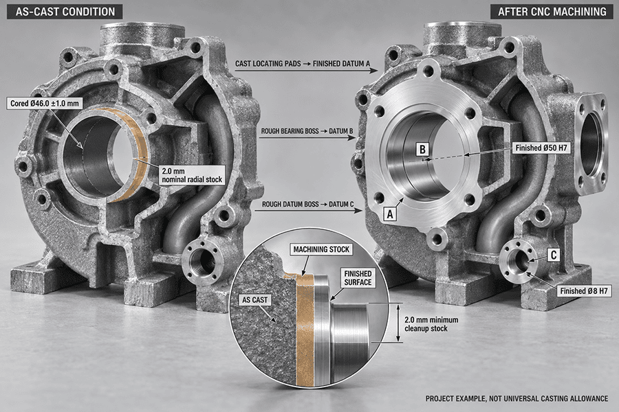
EPOC CRAFTER project data provides a useful example. An A356.0 aluminum pump housing was produced by gravity permanent mold casting with an expendable sand core. The main bearing boss started with a cored opening specified at Ø46.0 ±1.0 mm. Incoming measurements were Ø45.5 to 46.6 mm, with nominal 2.0 mm radial machining stock for a final Ø50 H7 bore.
The finished drawing required 50.000 to 50.025 mm with cylindricity no greater than 0.020 mm. Fine boring produced an FAI result of Ø50.013 mm and 0.011 mm cylindricity, checked by CMM and a calibrated bore gauge. The core created rough geometry and material around the feature. CNC created the bearing interface. That is the basic as cast vs machined decision for a precision metal casting.
For a feature that controls fit or assembly, use the finished drawing to define the requirement and use the CNC drawing tolerance guide to keep size, GD&T, and inspection callouts separate from the casting specification.
2. Process Selection Starts With Finished Features
The main types of casting are not interchangeable. Sand casting, shell molding, investment casting, permanent mold casting, gravity casting, high pressure die casting, centrifugal casting, and lost foam casting differ in tooling, mold system, repeatability, geometry, and downstream work. Investment casting is also widely called precision casting, but the name does not remove the need to define final functional tolerances.
ISO 8062-3 Annex A gives informative DCTG ranges that can normally be expected for particular casting methods, materials, sizes, and production conditions. The annex does not assign a mandatory grade to a process and does not prove an individual foundry’s capability. For example, its investment casting guidance changes with the largest overall dimension, and its pressure die casting guidance changes with size and complexity. Use those ranges for planning, then verify the actual supplier with production measurements.
| Sand casting and shell molding | Large or complex geometry, broad material options, cores | Cast variation, core location, surface condition | Machine CTQ bores, datums, mating faces, threads, and seals when the drawing requires it |
| Investment casting | Fine detail and complex shapes with expendable patterns | Part size, distortion, local feature capability | Keep as cast detail where proven; machine fits, datums, threads, and sealing interfaces |
| Gravity permanent mold casting | Repeat aluminum and other nonferrous parts with reusable tooling | Core strategy, heat treatment distortion, stock distribution | Good hybrid route when the body is near net shape but interfaces need CNC |
| High pressure die casting | High repeat volume and complex die formed geometry | Parting line, slides, die separation, internal porosity risk | Use die specific NADCA rules; limit machining to functionally justified features |
| Centrifugal casting | Rotational forms such as sleeves, rings, and cylinders | Radial geometry and final bore or OD requirements | Turning, boring, or grinding often defines the final interface |
| Lost foam casting | Complex shapes using an expendable foam pattern | Process capability and downstream cleanup must be supplier specific | Do not assume precision from the method name; define final features and inspection |
Common metal casting materials include aluminum alloys, steel, stainless steel, cast iron, zinc alloys, copper alloys, and other cast metals. Material changes solidification behavior, heat treatment, defect risk, machinability, and inspection. That is why an aluminum casting process should not inherit a tolerance or acceptance rule simply because a similar steel casting or iron casting uses it. Use the materials and properties guide when the material grade itself is still open.
2.1 Process specific standards stay inside their scope
ASTM B85/B85M-25 covers registered aluminum alloy die castings for general purpose applications. It is not a general specification for all aluminum casting. NADCA 2024 Product Specification Standards is also die casting specific. Its tolerance architecture separates normal linear dimensions, dimensions that cross a parting line, dimensions formed by moving die components, flatness, and machining stock. Do not copy those HPDC rules into gravity permanent mold casting, sand casting, or investment casting without another technical basis.
Run this decision before tooling is released. Stock, datum access, core location, and fixture contact surfaces need to be resolved while the casting drawing is still editable. That is the right point to use the DFM design guidelines.
2.2 When the casting process is still open
If the RFQ does not lock the process, compare metal casting methods against the finished feature set rather than quoting a process name first. A part with large simple geometry and lower tooling commitment may suit sand casting. Fine detail can favor investment casting or shell molding. Repeated aluminum housings with controlled external geometry may suit gravity permanent mold casting. High pressure die casting becomes relevant when production volume and die formed detail justify dedicated tooling. Centrifugal casting is a better fit for rotational forms. These are starting points, not automatic selections.
The sourcing question is then whether the chosen casting method reduces difficult material removal without moving too much risk into tooling, casting defects, or inspection. For metal casting parts with only a few CTQ interfaces, a cast blank plus selective CNC can be efficient. If nearly every surface needs precision machining, or the design is still changing, a billet route can be easier to control. That cast vs billet decision should be made before the foundry and machine shop quote different assumptions.
3. Metal Casting Process Steps That Affect CNC
The basic metal casting process steps are mold and core preparation, mold filling, solidification, part removal, gate and riser removal, cleaning, any required heat treatment, inspection, and secondary operations. For a machining supplier, the important point is the condition of the casting at the moment Setup 1 begins.
In the pump housing project, gate and riser removal, shot blasting, T6 heat treatment, straightening as required, and visual inspection were completed before datum establishing CNC work. The heat treatment sequence matters because distortion before Setup 1 changes the stock available for cleanup.
Accepted incoming castings showed flange bow of 0.18 to 0.42 mm over a 160 mm span after T6. Three additional pieces measured 0.68 to 0.74 mm and were straightened before machining. The lowest measured cleanup stock at one mounting pad edge was 1.6 mm against a project minimum of 1.5 mm. A nominal allowance can therefore look adequate in CAD and become marginal after casting variation and heat treatment.
3.1 Create the finished datum system early
Setup 1 located the housing on three cast datum pads with two side bosses for secondary and tertiary location. That setup machined datum A on the sealing face, datum B on the main bearing bore axis, and datum C on an Ø8 H7 dowel bore. Later setups located from machined A, B, and C instead of continuing to reference raw cast surfaces.
That sequence is worth preserving whenever several CTQ features must relate to each other. Raw casting variation still exists, but it no longer controls every later feature. For a broader example of how as cast dimensions, machining stock, and finished surfaces interact, the casting tolerance and machining stock guide covers the same split on ferrous parts.
4. Defects Become Critical at Functional Surfaces
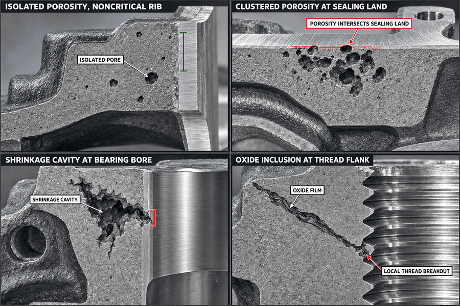
Metal casting defects matter by type, location, and function. Porosity in casting is not automatically a reject, and the same is true for shrinkage in casting or a local inclusion. A discontinuity inside a noncritical rib has a different consequence from one that opens into a sealing land, bearing wall, thread flank, or pressure boundary.
| Casting porosity | Rough machining exposed isolated pinholes near a noncritical rib and clustered porosity at a sealing land | Noncritical pinholes were accepted under the project zone rule; one sealing land part was rejected |
| Casting shrinkage | Rough boring exposed shrinkage cavities in two main bearing bosses | Both parts were rejected because the cavity intersected the final bearing bore wall |
| Casting inclusions | An oxide film intersected the P1 thread land during drilling and tapping | One part was rejected after local breakout appeared on the thread flank |
| Casting warpage | T6 distortion changed flange position before Setup 1 | Three parts were straightened, rechecked, and accepted before machining |
| Residual flash | Flash on two fixture pads prevented full locator seating | Flash was dressed locally and seating was rechecked before cutting |
This is also why casting inspection cannot be reduced to incoming visual inspection. A clean as cast surface can hide subsurface discontinuities that appear only after machining. The project records show that one porosity reject and two shrinkage rejects became relevant after material was removed. The defect mechanism existed before CNC, but the finished feature made it functional.
4.1 Inspection standards do not choose your acceptance level
ASTM E155-20(2026) provides reference radiographs for aluminum and magnesium castings, but it does not establish one universal severity level. Written acceptance criteria need to define the applicable area, discontinuity type, acceptable severity, and zoning when used. The inspection method and the acceptance criterion are separate decisions.
Material scope matters too. ISO 11971:2020 covers visual surface quality acceptance for steel and iron castings. It should not be used as the governing surface acceptance specification for aluminum, magnesium, or zinc die castings.
5. Machining Allowance Must Survive Real Variation
Casting machining allowance is the stock reserved so a later operation can reach the specified finished geometry. ISO 8062-3 uses required machining allowance, RMA, and ten required machining allowance grades: A, B, C, D, E, F, G, H, J, and K. The numerical RMA is selected from the standard by the casting’s largest overall dimension and the specified RMAG. A local machining allowance can also be indicated on an individual casting surface.
That system exists because one universal stock value is not defensible across all metal casting parts. A sealing face, a cored bore, a mounting pad, and a noncritical exterior wall do not have the same cleanup need. Sand casting, investment casting, permanent mold casting, and die casting also carry different dimensional behavior.
| Front sealing flange | 2.2 to 2.8 mm observed above finished plane | 2.0 mm minimum cleanup stock |
| Main bearing bore | Cored Ø46.0 ±1.0 mm, measured Ø45.5 to 46.6 mm | 2.0 mm nominal radial stock to Ø50 H7 |
| Opposite mounting face | 16.5 ±1.0 mm from cast datum pads | 2.5 mm nominal face stock |
| Seal bore | Cored Ø29.0 ±0.8 mm, measured Ø28.6 to 29.5 mm | 1.5 mm nominal radial stock to Ø32 H8 |
| Mounting pads | Cast above final mounting plane | 1.5 mm minimum cleanup stock |
These values are project data, not general recommendations. The useful check is whether the stock survives casting tolerance, mismatch, distortion, heat treatment movement, and fixture seating. If the stack consumes the available material, the cutter can reach final size before the whole surface cleans up.
Do not confuse casting machining allowance with finishing stock left by a CNC roughing operation. In the same project, rough machining left 0.25 to 0.40 mm on critical bores and 0.20 mm on the sealing face for the final pass. That is secondary machining strategy inside CNC, not the original casting RMA.
6. Which Cast Features Need CNC Finishing?
CNC machining of castings should be selective. Machine a feature when function requires tighter size, form, position, thread quality, or surface texture than the chosen casting route can demonstrate. Leave noncritical geometry as cast when its requirement is already met.
| Bearing or fit bore | Size, cylindricity, alignment, or fit controls assembly | Fine boring, reaming, honing, or grinding as required |
| Sealing face | Flatness and surface texture control leakage risk | Face milling or grinding, followed by flatness and roughness inspection |
| Datum feature | Downstream CTQ features reference it | Create early, then locate later setups from the machined datum system |
| Thread or threaded port | Flank geometry and engagement need controlled cutting | Drill and tap, thread mill, or finish the pilot before threading |
| Precision hole pattern | The relationship between holes matters as much as diameter | Machine from the finished datum reference frame and verify position |
| Cosmetic or nonmating surface | No fit, seal, datum, or CTQ role | Keep the casting surface finish when it meets the drawing |
The project sealing face required flatness no greater than 0.05 mm and Ra no greater than 1.6 µm. The FAI result after PCD face finishing was 0.028 mm flatness and Ra 0.74 µm. The Ø8 H7 datum bore finished at Ø8.009 mm with true position 0.034 mm against a Ø0.08 mm requirement to A and B. These are measured project results, not universal capability claims.
When a feature is function critical, the tight tolerance machining guide helps separate the few dimensions that need extra control from the rest of the part. The CNC machining capability page covers the downstream process once a cast blank is ready for machining.
7. Match Inspection to the Failure Mode
Casting quality control needs more than one instrument because each method answers a different question. A bore gauge checks size efficiently. A CMM checks position and GD&T. A profilometer measures surface texture. Radiography addresses internal discontinuities. Thread gauges check thread acceptance. A leak test checks functional sealing.
| Bore size and fit | Calibrated bore gauge plus CMM on FAI or defined samples | Confirms size without pretending size alone proves form |
| Position and GD&T | Bridge CMM aligned to the finished datum system | Checks relationships that hand tools cannot resolve |
| Surface roughness | Stylus profilometer | Separates Ra acceptance from flatness or dimensional acceptance |
| Internal discontinuities | Radiography when required by the inspection plan | Needs written severity and zoning criteria; method alone does not define pass or fail |
| Threads | GO and NO GO plug gauges | Checks thread acceptance directly |
| Leak performance | Defined pressure and hold test | Validates the housing function under the project test condition |
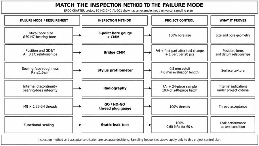
For the 240 piece pilot batch, critical bore size, threads, and the functional leak test were checked 100%. CMM inspection covered FAI, the first part after a tool change, and 1 part per 20 pieces. Radiography covered FAI plus a 24 piece production sample. Those frequencies belong to this project control plan and should not be copied into another casting inspection plan without a risk based reason.
All 236 accepted parts passed the project’s 0.60 MPa, 60 second static leak test with no visible leakage or out of limit pressure decay. That result applies to this housing and test condition only. For quality system and documentation context, see EPOC CRAFTER’s quality and certification controls.
8. Casting vs Machining: When the Hybrid Route Makes Sense
Casting vs machining is usually the wrong binary for complex metal parts. A cast vs billet decision is more useful when it compares full machining from stock, a near net shape casting with selective CNC, and a mostly as cast component. The right route depends on geometry, quantity, tooling commitment, material removal, CTQ features, design change frequency, and inspection burden.
| Cast plus selective CNC | Complex body, cored passages, repeated volume, limited set of CTQ interfaces | Casting creates bulk geometry; CNC controls fits, datums, sealing surfaces, and patterns |
| Full CNC from billet | Low quantity, frequent design changes, simple access, many surfaces already need machining | Avoids casting tooling and casting defect mechanisms, but can increase material removal and spindle time |
| Mostly as cast | Verified casting capability already meets the functional requirements | Lowest secondary machining content, but the casting process carries more of the dimensional and surface responsibility |
The pump housing used the hybrid route because the internal coolant passage, ribs, and bosses were efficient to create near net shape, while the bearing bore, seal bore, datums, threads, sealing face, and hole pattern needed controlled finished geometry. In the 240 piece batch, 236 parts were finally accepted. Four were rejected: two for shrinkage at the bearing boss, one for an oxide inclusion at a thread land, and one for porosity within a sealing land. Three additional warped castings were straightened before CNC and accepted after reinspection.
Those numbers describe one batch. They are not defect rates for A356.0, gravity permanent mold casting, or precision casting in general. When you compare machining castings with machining from billet, use project geometry and inspection cost rather than a generic claim that one route is always cheaper.
9. Put These Requirements in the RFQ
A custom metal casting RFQ should define the finished part, not only the alloy and casting method. The foundry and machine shop need the same view of the CTQ features, stock, datums, defect zones, inspection methods, and documentation. That prevents cast components from being accepted at one stage and becoming impossible to finish at the next.
| Drawing and CAD revision | Current casting drawing plus finished part drawing | Prevents tooling and machining from different revisions |
| Material and condition | Exact alloy, heat treatment, applicable specification | Keeps aluminum casting, steel casting, stainless steel casting, and iron casting requirements distinct |
| Casting method | Required process when already fixed | Stops a quotation from assuming the wrong tooling or tolerance basis |
| As cast vs machined features | Identify surfaces that remain as cast and those that need CNC | Lets the supplier plan stock, access, and inspection |
| Machining allowance | General RMAG or local project allowance where applicable | Provides cleanup stock without copying a universal value |
| Datum strategy | Raw locators for Setup 1 and final datum reference frame | Prevents casting variation from controlling all downstream CTQ features |
| Defect zones | Critical areas, discontinuity type, severity, and repair rules | Makes casting defects a functional acceptance issue instead of a vague ‘no porosity’ note |
| Inspection plan | Method plus sampling or 100% requirement where justified | Separates how you inspect from what passes |
| Records | MTR, heat treatment, FAI, CMM, radiography, leak test, NCR as required | Creates traceability without requesting documents that do not support a requirement |
| Surface finishing | Coating, blasting, polishing, or protected machined surfaces | Prevents finishing from shifting dimensions or damaging functional surfaces |
If coating, blasting, polishing, or another post process can change the finished dimension, review the surface finishing requirements before the drawing is released.
Before you release the RFQ, place the casting drawing, finished drawing, and inspection plan side by side. Every feature that changes status from as cast to machined should have a clear stock, datum, finished requirement, and acceptance path. That one check catches more sourcing risk than adding another generic note to the drawing.
Ready to Quote Your CNC Prototype?
Upload your STEP file and get a DFM review + quote within 12 hours.
No tooling cost. Minimum 1 part.
