

Dewey Wu General Manager & senior mechanical engineer at EPOC CRAFTER, 15 years in design engineering, quality, and metallurgy. Hands-on across CNC machining, metalwork, sheet metal, and prototyping (subtractive + 3D printing).
1. What Step Turning Changes on a Shaft
Step turning is a CNC lathe operation that machines two or more functional diameters on one rotating part. The step turning operation creates shoulders between those diameters, so a stepped shaft can carry a bearing on one journal, locate it against a shoulder, support a gear or coupling on another diameter, and provide a separate seal diameter. CNC step turning and step turning on a lathe describe the same basic feature strategy. The final result still depends on material, geometry, feature function, setup, surface requirement, quantity, and inspection method.
A correct diameter alone does not prove that a shaft will assemble or run correctly. A shaft bearing seat can require a size limit, bearing fit tolerance, shaft shoulder location, surface texture, form control, and shaft runout control. Those requirements are separate. Single setup turning can reduce variation introduced by reclamping, but it cannot remove error from chucking, deflection, spindle condition, tool wear, heat, or measurement.
Use CNC machining process planning when the drawing includes turned features plus holes, flats, slots, or other operations outside basic shaft turning.
Step turning should be planned as a set of functional relationships, not as a sequence of diameter reductions. Shaft turning, CNC lathe turning, CNC shaft machining, and precision shaft machining all begin with the same question: which feature controls assembly, rotation, sealing, or axial location?
2. Shoulders Bearing Seats and Relief Grooves
Bearing seat turning and bearing journal turning require more than a nominal diameter. The journal must provide the specified fit with the mating bore, while the shoulder must locate the component axially. A shoulder may also need shoulder perpendicularity when the mounted component must seat squarely. The drawing should state the functional feature relationship instead of relying on a vague sharp-shoulder note.
A lathe tool nose radius and a turning tool nose radius are machining variables. They affect the corner left by the insert, cutting force, and tool path. They do not define the clearance needed by the part. A shaft relief groove, shoulder relief groove, or turning undercut becomes necessary only when the mating component, subsequent machining route, or drawing requirement needs controlled corner clearance. ISO 18388 standardizes general purpose relief groove types and drawing designations. It does not require every 90 degree shoulder to have an undercut.
Engineering judgment: specify a relief feature when a bearing, gear, seal component, or finishing route needs clearance at the corner. An unnecessary groove can reduce local section strength, add machining time, and create another feature to inspect.
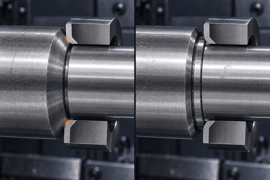
Choose the mating relationship through ISO fit selection for mating parts, not from the word bearing alone.
3. Size Fit Datum and Geometric Control
Shaft tolerance, shaft diameter tolerance, and ISO fits and tolerances control size or the intended relation with a mating hole. They do not define shaft roundness, shaft cylindricity, shaft coaxiality, turning runout, or shoulder orientation. ISO 286 provides a system of limits and fits. The correct class still depends on nominal size, mating bore, function, assembly method, temperature, material condition, and service requirement.
| Size tolerance | Permitted journal diameter limits | Roundness, runout, shoulder location |
| Fit designation | Relation with the mating hole | Journal form or datum relationship |
| Roundness | Circular form at one cross section | Relationship to a datum axis |
| Cylindricity | Form of a full cylindrical surface | Axial location of a shoulder |
| Circular runout | Variation at one circular section relative to a datum axis | Full surface variation |
| Total runout | Variation across a controlled surface relative to a datum axis | Mating fit unless size is also specified |
ISO 1101 distinguishes form requirements from datum-related orientation, location, and runout requirements. A cylindrical bearing journal can establish a datum axis when the drawing identifies it as a datum feature. A shoulder face can establish a datum plane. ISO 5459:2024 defines a datum through association with the real datum feature. The datum is not the chuck, fixture, spindle axis, or CNC program zero.
Same setup machining can support a functional datum strategy, but it is a manufacturing choice rather than an ISO requirement. Use a common datum only when the drawing defines the required common datum system. Do not use shaft coaxiality as a generic substitute for the actual datum-related characteristic stated on the drawing.
Apply the drawing language through this tolerances and standards guide before assigning a geometric tolerance.
4. Workholding and Inspection
Long shaft turning, slender shaft turning, and shaft deflection turning need a workholding plan before the program is released. A short rigid shaft may be suitable for a chuck or collet. A long journal with a runout or surface requirement can need centers, a steady rest, a soft jaw, or another support method. Turning between centers can help maintain relationships across multiple diameters when center holes and part geometry permit it. It does not remove the need to control support stiffness, cutting load, center condition, and measurement.
Inspection must match the drawing requirement. A micrometer can check a diameter when access and required uncertainty are suitable. It does not establish shaft runout measurement, bearing seat inspection, roundness measurement, or cylindricity measurement. Circular runout evaluates radial variation at a stated circular section relative to a datum axis. Total runout evaluates variation across the controlled surface relative to that datum axis.
ISO 12181-2:2011 treats a roundness result as the output of a complete specification operator. Transmission band, filtering, probing system, stylus geometry, sampling, and association method can affect the reported value. A bearing journal roundness result without its agreed measurement and evaluation conditions is not sufficient evidence for acceptance. ISO 12181-2:2011 does not provide a universal bearing journal limit or a mandatory report template.
A surface texture value is also separate from size and runout. ISO 21920 uses stated parameters and evaluation conditions for surface texture. A low Ra result alone does not establish bearing fit, sealing performance, or runout compliance.
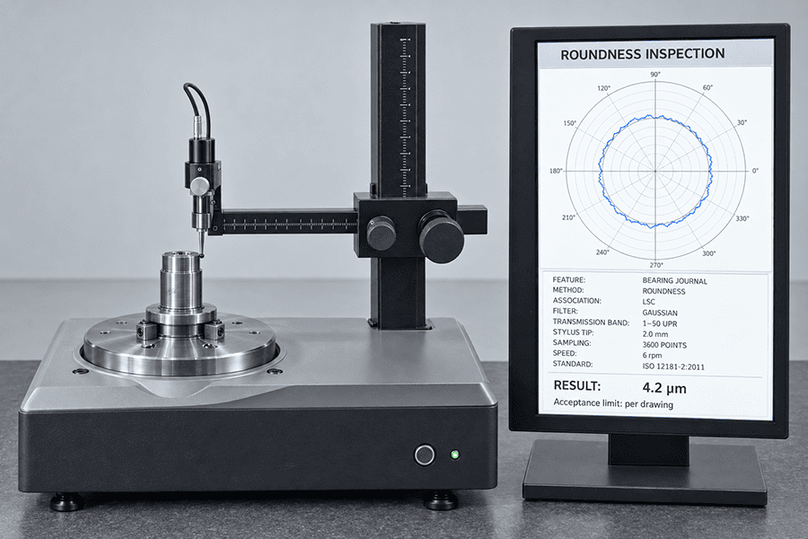
Bring workholding risks into the quote through DFM design guidelines before a supplier chooses the turning route.
Check material condition through the materials and properties guide when heat treatment, coating, polymer compliance, or machinability changes the route.
5. Applications Drawing Inputs and FAQ
Pump shaft machining, drive shaft machining, automotive shaft machining, gear shaft machining, robot shaft machining, and medical shaft machining use step turning when several functional cylindrical features share one axis. Step turning is not the right route for every nonuniform part. Large diameter differences can create excessive material removal. Nonaxisymmetric features, thin walls, unstable long sections, hardened journals, and later grinding or milling can require a different route or a secondary operation.
A stepped shaft RFQ should identify material grade and condition, functional diameters, mating fit, datum features, shoulder features, relief geometry where required, geometric controls, surface texture requirements, inspection evidence, drawing revision, quantity, packaging, destination, and documentation. This lets the supplier identify the actual risk before the part is cut.
Prepare those inputs with the CNC machining quote checklist so the quotation reflects the drawing, inspection, and delivery scope.
What is step turning?
Step turning machines two or more diameters on a rotating workpiece. The resulting shoulders can provide locating, assembly, load support, or transmission functions.
What is a stepped shaft?
A stepped shaft has two or more cylindrical diameter sections along one axis, with shoulders between adjacent sections.
How does step turning work?
The lathe removes material from selected axial sections to create the required diameters, then finishes the functional journals, shoulders, and any specified relief features.
Why machine a shaft in one setup?
A single setup can reduce reclamping variation between related features. It does not guarantee roundness, cylindricity, or runout without the specified process control and inspection.
How to measure shaft runout?
Mount and rotate the part relative to the datum arrangement required by the drawing, then measure the specified feature with a suitable indicator or measurement system. The method must match circular or total runout.
What is the difference between circular runout and total runout?
Circular runout is evaluated at a circular section. Total runout is evaluated across the controlled surface. Both are datum-related controls.
What is the difference between roundness and cylindricity?
Roundness controls one circular cross section. Cylindricity controls the form of the full cylindrical surface.
How to machine a bearing seat?
State the functional diameter, fit, shoulder requirement, relief requirement where needed, surface texture, geometric controls, datum system, and inspection evidence before the machining route is selected.
What is a turning relief groove?
A turning relief groove is a controlled clearance feature at a shoulder or corner. It prevents an insert radius or mating component corner from interfering with seating when the drawing requires that clearance.
A stepped shaft is ready for quotation when its diameter, fit, shoulder, datum relationship, and inspection request describe the same function. Use low volume production planning when the part needs a controlled route from drawing review through delivery.
Ready to Quote Your CNC Prototype?
Upload your STEP file and get a DFM review + quote within 12 hours.
No tooling cost. Minimum 1 part.
