

Dewey Wu General Manager & senior mechanical engineer at EPOC CRAFTER, 15 years in design engineering, quality, and metallurgy. Hands-on across CNC machining, metalwork, sheet metal, and prototyping (subtractive + 3D printing).
PETG filament is a glycol-modified thermoplastic polyester used in FDM 3D printing for functional prototypes, electronics enclosures, brackets, and fixtures. It offers useful toughness, layer bonding, and chemical resistance, but its performance depends on the specific material grade, moisture condition, printing parameters, and part geometry. Heat resistance also needs careful evaluation, particularly for parts carrying sustained loads. This guide covers PETG properties, printing temperatures, drying, common defects, and the checks needed before selecting it for an engineering application.
1. What Is PETG Filament?
PETG stands for polyethylene terephthalate glycol-modified. It belongs to the thermoplastic copolyester family and is commonly supplied as filament for fused deposition modeling (FDM), also called fused filament fabrication (FFF).
The PETG meaning is glycol modified polyethylene terephthalate. PETG 3D printer filament is one common feedstock form of this PETG plastic; the name alone does not identify a complete resin specification. A PETG polymer designation should still identify copolyester chemistry and the actual commercial grade.
PETG is produced by modifying polyester chemistry to change properties such as crystallization behavior, processability, and toughness. Its relatively low crystallization tendency in common filament grades helps reduce shrinkage and warping during printing. For a broader comparison of polymer families, 3D printer filament material selection.
Compared with many standard PLA filaments, PETG offers a different balance of toughness, flexibility, and temperature-dependent behavior. It is often considered for functional parts that need more resistance to cracking or repeated handling. That does not make PETG universally stronger, more heat resistant, or more dimensionally stable than PLA. Those comparisons depend on the grades, manufacturing conditions, and properties being measured.
1.1 PETG vs PET: Polymer Identity and Grade Differences
PET and PETG are related polyester materials, but their names do not establish identical chemical compositions or processing behavior.
PET vs PETG is a chemistry and processing comparison, not proof of identical tensile or thermal properties. A PETG copolyester may use different glycol comonomers and additives.
PET is based on ethylene glycol and terephthalic acid-derived units. PETG grades commonly incorporate additional glycol-derived units, such as cyclohexanedimethanol-derived units, to modify the polymer structure and crystallization behavior.
ISO 20028-1:2019 provides a designation system for thermoplastic polyester materials. It identifies polymer chemistry, fillers and reinforcements, intended processing applications, and designated property classes. The standard does not assign one chemical formulation or one set of mechanical properties to every product sold as PETG.
Two PETG filaments can therefore behave differently even when they share the same nominal diameter. Their polymer grades, additives, pigments, molecular characteristics, and manufacturing histories may differ.
Specify the actual filament grade when comparing tensile properties, drying conditions, and extrusion behavior.
2. PETG Material Properties
PETG resin data cannot be substituted for FDM part properties. Printed roads, voids, and build direction affect the measured response.
When evaluating PETG strength, PETG tensile strength and PETG density, first identify the test specimen and printing direction. FFF 3D printing creates deposited-road interfaces that can change the finished part response.
Check whether reported properties come from injection-molded specimens or printed coupons, and record the loading direction.
Check each property against the actual part requirement.
| Property | What It Tells You | Engineering Consideration |
| Tensile strength | Maximum engineering stress under the stated test method | Depends on specimen preparation, grade, and print orientation |
| Tensile modulus | Stiffness under small tensile strains | Useful for deflection analysis but not a complete measure of part stiffness |
| Elongation at break | Deformation sustained before fracture | Sensitive to layer bonding, specimen geometry, and test conditions |
| Impact resistance | Response to sudden loading | Requires a defined impact test, specimen, and notch condition |
| Chemical resistance | Material response to contact with specific substances | Depends on chemical concentration, temperature, stress, and exposure duration |
| Density | Mass per unit volume of the material | Printed-part mass also depends on infill, internal voids, and geometry |
| Dimensional stability | Ability to retain geometry under manufacturing and service conditions | Affected by shrinkage, thermal exposure, loading, and time |
A material property does not establish the load capacity of a printed bracket.
2.1 Tensile Strength, Modulus, and FDM Build Orientation
Tensile strength describes the stress a specimen withstands under a specified tensile test. Tensile modulus describes its initial elastic stiffness. Elongation describes how much the specimen stretches relative to its original gauge length.
Higher tensile strength does not necessarily mean greater stiffness or elongation at break.
ASTM D638-22 provides a method for determining tensile properties of plastics using defined specimen geometries, conditioning, loading speeds, and strain measurements. The underlying stress calculation is covered in tensile stress in 3D printed parts.
For a flat specimen, engineering tensile stress is calculated from the applied force and its original measured cross-sectional area:
σ = F / A₀
where:
- σ = engineering tensile stress, MPa
- F = applied tensile force, N
- A₀ = original measured cross-sectional area, mm²
Tensile modulus is determined from the appropriate initial stress-strain region. It should not be calculated simply by dividing maximum tensile stress by strain at break.
Why does print orientation matter?
An FDM-printed PETG specimen does not have the same internal structure in every direction.
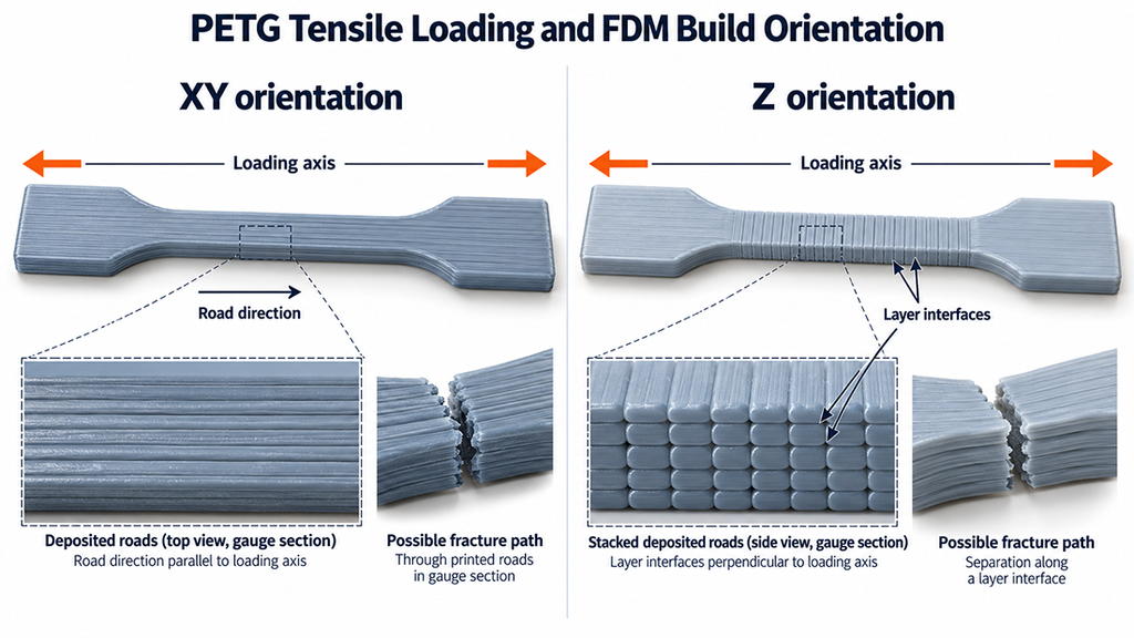
In an XY-oriented specimen, tensile loading may act primarily along deposited filament roads. In a vertically printed Z-oriented specimen, loading can act across multiple layer interfaces. The latter configuration places greater importance on interlayer fusion and interface defects.
Layer orientation changes the likely fracture path.
For meaningful comparison, record the build orientation relative to the loading axis. An XY tensile result cannot automatically qualify a Z-loaded component.
Layer height, extrusion temperature, cooling, perimeter count, raster direction, and filament moisture condition also influence the printed structure. Changing these variables can alter the result even when the same PETG grade is used.
ASTM D638-22 calls for appropriate specimen selection and repeat testing. For the anisotropic conditions covered by the method, at least five valid specimens per orientation are needed. Report individual results together with the mean and variability, rather than selecting the strongest coupon.
The specimen’s actual width and thickness must be measured. Using the nominal CAD cross-section can introduce error into the calculated tensile stress.
A reliable PETG tensile comparison should identify:
- Commercial material grade and filament lot
- Specimen type and preparation method
- XY, on-edge, or Z build orientation
- Printing parameters and raster arrangement
- Conditioning and test environment
- Test speed and strain measurement method
- Tensile strength, modulus, elongation, and fracture location
- Specimen count, mean, and variability
A bracket may fail at a hole, insert boss, or layer interface before the test coupon reaches its reported tensile strength.
2.2 Impact Resistance, Chemical Resistance, and Dimensional Behavior
Impact resistance
PETG is commonly chosen for parts that need some resistance to cracking during handling, installation, or accidental knocks.
This matters for protective housings and mounting components.
Still, toughness and impact strength are not interchangeable. An impact result depends on the selected method, specimen thickness, notch geometry, temperature, and preparation conditions.
A reported impact value from a molded specimen should not be treated as proof that a printed PETG component will survive the same impact.
Layer interfaces, sharp corners, thin sections, and mounting features can change the failure path. Parts exposed to repeated impacts or sudden loads need testing in their intended configuration.
Chemical resistance
PETG can resist contact with certain chemicals, but chemical resistance is not a universal material property.
The relevant question is which chemical reaches the part, at what concentration and temperature, for how long, and under what mechanical stress.
A part exposed briefly to a cleaning solution may behave differently from one continuously stressed while immersed in the same liquid.
Chemical exposure can also cause swelling, surface damage, or environmental stress cracking in susceptible grades and conditions.
For enclosures and fixtures exposed to oils, cleaners, solvents, or process fluids, use chemical compatibility information for the specific grade and evaluate the actual exposure conditions.
Density and dimensional stability
Material density helps estimate part weight, but the density of a fully consolidated polymer is not the same as the effective density of a printed component containing infill spaces.
Two PETG parts with the same outside dimensions can have different masses and stiffness because of their internal structures.
PETG’s relatively limited crystallization and shrinkage during typical FDM processing can make warping easier to manage than with some other thermoplastics. It does not eliminate distortion.
Uneven cooling, insufficient bed adhesion, thin walls, long unsupported features, and residual stress can still produce dimensional changes.
For a functional assembly, check the features that control fit and load transfer:
- Mounting hole diameter and spacing
- Contact-surface flatness
- Boss and standoff height
- Insert seating and surrounding wall condition
- Clearance around mating components
These measurements control assembly fit.
Validate mounting fit under the expected load and temperature.
3. PETG Heat Resistance and Service Temperature
PETG can be used for some functional parts exposed to moderate temperatures, but its heat resistance depends on more than the temperature printed on a filament datasheet.
A PETG bracket holding a lightweight PCB may remain dimensionally stable at room temperature yet gradually deform when installed near a heat source. The polymer does not need to melt for the mounting surface to shift or the fastener contact area to lose stiffness.
Three factors deserve attention: the material’s glass transition temperature, its response to bending under heat, and the duration of the applied load.
3.1 Glass Transition, HDT, and Creep
Glass transition temperature (Tg)
PETG is commonly supplied as an amorphous or predominantly amorphous copolyester. Its glass transition temperature describes a change in molecular mobility and viscoelastic behavior, not a single temperature at which the material suddenly fails.
Commercial PETG grades commonly report glass transition temperatures in the approximate 75 to 85°C region. Confirm the actual grade and test method before using a value in design.
As temperature approaches the glass transition region, the polymer generally becomes less stiff. A printed component may show greater deflection under the same load.
Tg does not tell you how long a bracket can carry a load or whether an enclosure will retain its mounting dimensions.
PETG glass transition temperature differs from PETG heat deflection temperature. PETG melting point and PETG melting temperature queries can be misleading for predominantly amorphous PETG grades: a sharp crystalline melting point may not describe their thermal response. PETG softening temperature also cannot by itself qualify sustained service loads.
Heat deflection temperature (HDT)
HDT describes the temperature at which a standardized specimen reaches a specified deflection under prescribed flexural loading and heating conditions.

It is a test result tied to the load level, specimen geometry, orientation, and heating procedure.
A PETG grade can therefore have different reported HDT values depending on the test conditions. Results obtained under different loading levels or methods should not be placed in a comparison table without identifying those differences.
HDT is useful for comparing materials under controlled conditions. It does not establish the maximum continuous operating temperature of a finished FDM part.
The printed part has its own geometry, internal structure, layer interfaces, and mounting constraints, none of which are fully represented by a standard HDT specimen.
Creep and elevated-temperature dimensional stability
Creep is time-dependent deformation under sustained stress.
A PETG component may continue to deflect under a constant load even when the temperature is below its reported Tg or HDT. Higher temperatures can accelerate this process because the polymer’s mechanical response is temperature-dependent.
Consider a printed electronics mounting bracket held against an aluminum chassis. The fasteners introduce local compression at the contact surfaces, while the supported assembly loads the bracket and its upright bosses.
The bracket may initially fit correctly. Over time, sustained contact pressure can produce deformation around the washer seats or changes in the supported height. Heating can increase those effects.
The relevant failure may be a loss of alignment or clearance rather than fracture.
For a loaded PETG component, evaluate:
- The operating temperature and duration of exposure
- Sustained and intermittent loading
- Local contact pressure around screws and inserts
- Build orientation and layer interfaces
- Changes in mounting dimensions after thermal exposure
- Residual deformation after unloading and cooling
A short heating test without a representative load cannot establish long-term creep resistance. Likewise, a room-temperature tensile test does not qualify a printed component for prolonged service at elevated temperature.
For the electronics bracket considered later in this article, the intended environment includes normal operation at 20 to 40°C and intermittent exposure to 50°C. Those conditions define the thermal verification problem; they do not, by themselves, demonstrate that the bracket will retain its dimensions during service.
The appropriate decision is based on the component’s actual load, allowable displacement, exposure time, and functional checks rather than a universal PETG service-temperature claim.
4. PETG Printing Temperature and Process Settings
PETG printing settings affect more than surface appearance. Nozzle temperature, cooling, extrusion flow, and print speed determine how deposited roads fuse together and how accurately a part retains its geometry. Production routes and available FDM capabilities are described under FDM additive manufacturing processes.
PETG print settings should cover PETG nozzle temperature, PETG bed temperature, PETG fan speed and PETG retraction settings. A practical PETG print temperature depends on grade and nozzle throughput; one PETG temperature range should not be applied to every product.
A setting that produces a clean enclosure may not provide the best layer bonding for a loaded bracket. Start with the filament manufacturer’s recommended profile, then adjust the process according to the part’s geometry, orientation, and functional requirements.
4.1 Nozzle Temperature, Bed Temperature, and Cooling
Nozzle temperature

Many conventional PETG filaments are printed at nozzle temperatures around 230 to 250°C. This is a common starting range, not a universal processing requirement.
A higher nozzle temperature can improve material flow and fusion between deposited roads. It can also increase stringing, oozing, and surface defects when the melt remains too fluid during travel movements.
An excessively low temperature may reduce fusion between adjacent roads and layers. The resulting print can look acceptable while containing weak interfaces.
The correct setting depends on the PETG grade, nozzle geometry, extrusion flow, print speed, and cooling conditions.
Bed temperature
PETG commonly uses a heated build plate, with many conventional printing profiles operating around 70 to 90°C.
Bed temperature influences first-layer adhesion and the cooling behavior of the printed base. Insufficient adhesion can allow edges to lift, especially on wide or thin parts.
Excessively strong adhesion presents a different problem. PETG can bond tightly to certain smooth PEI surfaces, creating a risk of damage during removal.
Build-plate material, surface condition, and the manufacturer’s recommended release procedure matter as much as the nominal temperature.
Cooling
Part cooling affects the time available for adjacent roads and layers to fuse.
Strong cooling may improve bridges, overhangs, and small features, but it can reduce bonding when deposited material loses heat too quickly. Reduced cooling can improve fusion in some configurations while increasing stringing or reducing detail quality.
The goal is not to maximize or minimize fan speed. It is to obtain adequate layer bonding while controlling feature accuracy and visible defects.
| Process Variable | What It Influences | Practical Adjustment |
| Nozzle temperature | Melt flow, road fusion, stringing | Adjust within the specific filament and equipment profile |
| Bed temperature | First-layer adhesion, edge lifting | Match the build surface and base geometry |
| Part cooling | Layer bonding, bridges, overhangs | Balance mechanical requirements with feature quality |
| Extrusion flow | Road width, contact between adjacent roads, dimensional accuracy | Check actual deposited width and signs of overextrusion |
| First-layer setup | Base adhesion, surface contact, initial dimensional consistency | Verify nozzle offset and first-layer deposition |
| Chamber conditions | Cooling rate and thermal consistency | Record ambient or controlled chamber conditions where relevant |
These variables interact. Increasing nozzle temperature without checking extrusion flow and cooling can replace one defect with another.
4.2 Print Speed, Layer Bonding, and Build Orientation
Print speed and material flow
PETG print speed should be selected with the hot end’s melting capacity, nozzle size, layer height, and extrusion width in mind.
As print speed increases, the required volumetric flow increases for the same deposited cross-section. When the extrusion system cannot melt and deliver material consistently, the result may include underextrusion, gaps, or reduced inter-road contact.
Reducing print speed can improve extrusion consistency, but it does not automatically produce stronger parts. Layer bonding also depends on temperature, cooling, material condition, and the time between deposited layers.
For functional components, separate external perimeter quality from internal deposition performance. Both can affect dimensional accuracy and load transfer.
Layer height and deposited-road geometry
Layer height changes the shape and contact geometry of deposited roads.
A smaller layer height may improve surface detail, but it does not guarantee higher tensile strength in every direction. Extrusion width, perimeter count, raster arrangement, and thermal history must also be considered.
Internal infill contributes to load transfer, but a nominal infill percentage does not directly establish the stiffness or load capacity of a completed part.
For mounting brackets and enclosures, perimeter layout, local reinforcement, screw-seat geometry, and load direction can be more important than increasing infill alone.
Build orientation
Build orientation determines how the printed layers intersect the main load path.
A bracket printed flat may place its base predominantly in the XY plane. Upright mounting bosses and their roots can still experience stresses that challenge the layer interfaces.
Orienting the entire component differently may improve one loaded feature while making another more vulnerable.
Choose orientation by examining the complete load path, including fasteners, supporting surfaces, ribs, and changes in cross-section.
The PETG electronics mounting bracket addressed later in this article uses a flat XY build orientation, a 0.20 mm layer height, a 0.45 mm extrusion width, four perimeters, and 35% gyroid infill. Its listed process temperatures are 245°C at the nozzle and 85°C at the bed.
These settings describe the specified manufacturing configuration for that bracket. They are not universal PETG recommendations or evidence of the bracket’s final mechanical performance.
Dimensional control
PETG dimensional accuracy depends on more than printer positioning accuracy.
Extrusion width, cooling, material shrinkage, support removal, and local feature geometry can affect holes, bosses, walls, and mating surfaces.
Check dimensions after the part has cooled and any required post-processing is complete. Critical holes and insert locations need particular attention because assembly forces can introduce additional deformation.
For parts with heat-set inserts, verify the insertion procedure, surrounding polymer condition, and mating fastener engagement. A correctly positioned insert does not establish that the boss can withstand the required service load.
Retain the print profile only after its critical dimensions and functional features meet the acceptance criteria.
5. PETG Moisture Absorption, Drying and Storage
PETG filament absorbs moisture from the surrounding air. When moisture-containing filament enters a hot nozzle, the water can vaporize and disturb the molten polymer flow. You may notice popping sounds, bubbles, rough extrusion, or inconsistent deposited roads.
A PETG filament dryer is useful when the material requires conditioning, but the correct set point comes from that grade and dryer design. When users ask how to dry PETG filament, start with the manufacturer’s temperature and time guidance and verify consistent extrusion.
Moisture can also contribute to polymer degradation during processing. The effect depends on the material grade, moisture content, melt temperature, and exposure time.
A print with visible stringing is not necessarily wet. Retraction, nozzle temperature, travel movements, and cooling can produce similar symptoms. Check the material condition before treating every surface defect as a drying problem.
5.1 How to Dry and Store PETG Filament
Drying temperature and time
PETG drying temperature should come from the specific filament manufacturer’s instructions and the capabilities of the drying equipment.
The required drying time depends on the filament’s initial moisture condition, airflow, temperature uniformity, spool arrangement, and target condition. A longer drying cycle is not automatically better.
For example, the electronics mounting bracket case in this article specifies a dry-air conditioning cycle of 65°C for six hours. That is a case-specific process setting, not a universal PETG drying requirement.
Check that the selected temperature is compatible with both the filament and its spool. Excessive heating can distort the spool, affect winding, or deform the filament.
ISO/ASTM 52903-1:2020 addresses moisture-sensitive feedstock through appropriate packaging and supplier-recommended storage conditions. It does not establish one mandatory PETG drying temperature, duration, or moisture limit.
Storage and handling
Keep unused filament in packaging that limits moisture exposure, particularly when storage periods are long or the workshop is humid.
For production work, record the filament grade, lot identification, storage condition, and drying cycle. A spool label helps maintain traceability, but it does not establish that the filament is dry or that its properties remain unchanged.
| Condition or Observation | Possible Cause | Practical Check |
| Popping or bubbles during extrusion | Moisture vaporizing in the melt | Check storage history and evaluate a controlled drying cycle |
| Rough or inconsistent extruded roads | Moisture, unstable flow, or partial nozzle restriction | Examine extrusion consistency and material condition |
| Stringing between features | Temperature, retraction, travel settings, or moisture | Check the print profile before attributing the defect to water |
| Filament feeding resistance | Tangled winding, spool drag, or filament deformation | Inspect spool rotation and feed-path compatibility |
| Brittle filament or unexpected fracture | Material degradation, formulation, storage, or processing history | Compare material condition and examine the failure location |
What should be verified after drying?
Start with a consistent extrusion check using the same filament grade and printer configuration. Compare the deposited surface, extrusion stability, and recurring defects before and after the drying process.
For parts where layer bonding affects the functional load path, improved visual appearance alone is insufficient evidence of increased mechanical strength. Mechanical verification must use specimens and printing conditions appropriate to the part.
The purpose of PETG moisture control is to maintain repeatable feedstock and extrusion behavior. Drying is one controlled step in that process, not a substitute for correct printing parameters or finished-part inspection.
6. Common PETG Print Defects and Troubleshooting
PETG printing defects often share similar symptoms but have different causes. Stringing may come from excessive melt flow during travel moves. Rough surfaces may indicate moisture, unstable extrusion, or incorrect temperature settings. Layer separation can develop even when the outside of a part looks acceptable.
PETG stringing, PETG warping, PETG delamination and PETG not sticking to bed are distinct troubleshooting questions. PETG bed adhesion depends on the surface and initial layer, whereas interlayer adhesion depends on deposited-road fusion.
Identify where the defect occurs before changing the print profile. A problem limited to the first layer needs a different investigation from one appearing around upright bosses or between internal layers.
| Print Defect | What to Look For | Likely Causes | Corrective Action |
| PETG stringing | Fine strands between separated features | Nozzle temperature, retraction, travel settings, or moisture | Check filament condition, then adjust temperature and travel settings |
| Warping | Corners lifting or a distorted base | Uneven cooling, poor first-layer contact, or residual stress | Check build surface, bed temperature, first-layer deposition, and part geometry |
| Poor bed adhesion | First layer detaches or moves during printing | Incorrect nozzle offset, contaminated build surface, or unsuitable bed conditions | Clean the plate using the approved procedure and verify first-layer contact |
| Excessive bed adhesion | Part resists removal or damages the print surface | PETG bonding too strongly to certain surfaces | Use the recommended build plate or release procedure |
| Underextrusion | Gaps, incomplete walls, or inconsistent road width | Restricted nozzle, unstable feeding, or excessive volumetric flow | Inspect the feed path, nozzle, extrusion flow, and print speed |
| Bubbling or rough extrusion | Popping, visible bubbles, or irregular surface texture | Moisture, material degradation, or unstable extrusion | Check drying history and inspect extrusion consistency |
| Layer separation | Cracks or splits following layer interfaces | Inadequate fusion, excessive cooling, poor deposition, or unfavorable loading direction | Check road contact, thermal settings, cooling, and build orientation |
Start with the defect location.
For stringing, inspect travel movements and retraction before repeatedly increasing the drying temperature. A controlled test with the same geometry helps reveal whether the change reduces unwanted extrusion.
For warping, look at the first-layer contact pattern and the shape of the part. A wide base with thin edges can develop uneven thermal contraction. Raising bed temperature alone may not correct the underlying geometry or cooling problem.
For underextrusion, inspect whether the missing material appears throughout the print or only during high-flow sections. A restriction in the nozzle and insufficient melt capacity can produce similar gaps but require different corrections.
Layer separation deserves particular attention in functional components. A crack at the root of an upright mounting boss may indicate inadequate bonding, unfavorable load transfer, or excessive stress concentration. Increasing nozzle temperature cannot correct every structural weakness.
Change one process variable at a time when diagnosing a repeatable defect. Record the adjustment and examine the next print under comparable conditions.
After a successful adjustment, inspect critical dimensions and functional features again. Better surface appearance does not automatically mean that the part has improved strength, dimensional accuracy, or resistance to sustained loading.
7. PETG Applications and Engineering Selection
PETG is a practical candidate for functional prototypes, electronics enclosures, mounting brackets, protective covers, and light-duty fixtures. Its usefulness comes from the combination of toughness, printability, and resistance to certain environmental exposures. Before committing to a production process, rapid prototyping for functional parts.
PETG filament uses include fixtures and enclosures, but PETG transparent filament requires separate optical-surface checks. PETG chemical resistance and PETG UV resistance also depend on grade and exposure, not the polymer label alone.
The application determines which property matters most. An enclosure may need impact resistance and accurate connector openings. A mounting bracket must retain its shape around screws and standoffs. A fixture may need adequate stiffness under repeated handling.
PETG is not automatically suitable for outdoor exposure, high temperatures, heavily loaded structures, or chemically aggressive environments. Those applications require grade-specific evaluation and testing.
7.1 When to Choose PETG Instead of PLA or ABS
PETG, PLA, and ABS can all produce functional FDM components, but each presents different manufacturing and service considerations.
| Selection Factor | PETG | PLA | ABS |
| Printability | Usually printable on an open machine; grade and build surface affect adhesion | Usually straightforward with relatively low warping | More sensitive to cooling, shrinkage, and warping |
| Toughness | Useful for parts requiring resistance to cracking and handling damage | Depends on grade; standard PLA can be relatively brittle | Often suitable for impact-resistant functional components |
| Heat resistance | Grade-dependent; sustained-load deformation requires evaluation | Standard grades may lose stiffness at relatively modest temperatures | Often offers greater heat resistance than conventional PLA or PETG grades |
| Dimensional control | Generally manageable, with local distortion still possible | Often good under suitable conditions | Requires greater attention to shrinkage and thermal control |
| Chemical exposure | Requires chemical-specific compatibility checks | Requires chemical-specific compatibility checks | Requires chemical-specific compatibility checks |
| Typical applications | Electronics brackets, protective covers, functional prototypes | Concept models, prototypes, low-load indoor parts | Functional housings and components needing higher thermal capability |
These comparisons describe general material behavior, not guaranteed performance rankings. Modified PLA, reinforced PETG, and specialized ABS grades can behave differently.
For an indoor electronics enclosure with moderate mechanical loads, PETG may provide a useful balance of toughness and process control. For a dimensionally sensitive model without demanding service loads, PLA may be sufficient. ABS deserves consideration when the application requires its particular thermal or mechanical characteristics and the printing process can control distortion.
Compare the specific grades and their relevant test conditions before making the final choice.
7.2 Engineering Case: PETG Electronics Mounting Bracket
An indoor electronics mounting bracket provides a useful example of how PETG selection connects to actual part geometry, fastening conditions, and thermal exposure.
Part configuration
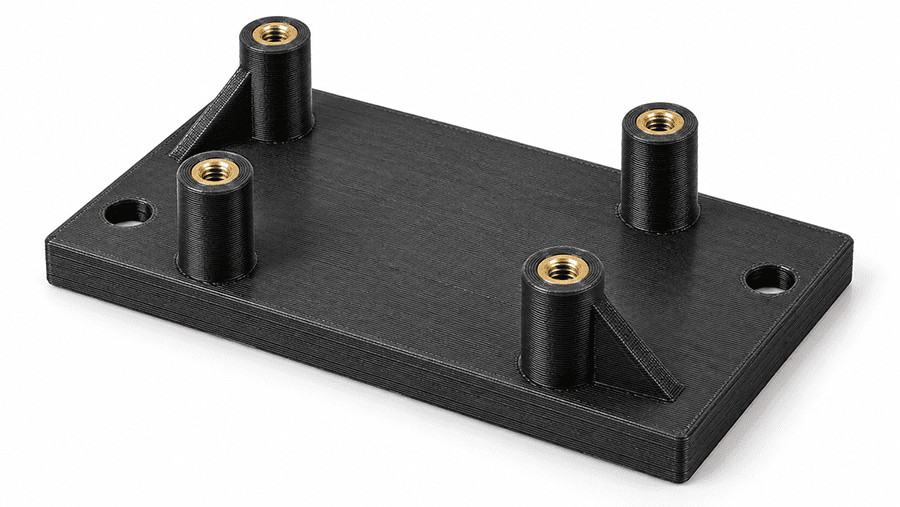
The EC-PETG-2026-1009 case defines a bracket for a non-safety-critical industrial electronics enclosure. The component mounts to an aluminum chassis through two fastening holes and supports a PCB assembly at four raised positions.
The specified geometry and loading conditions are:
| Engineering Parameter | Case Value |
| Material | Prusament PETG, Jet Black, 1.75 mm |
| Part envelope | 100 × 60 × 22 mm |
| Base thickness | 6 mm |
| PCB support bosses | Ø8 mm, 16 mm above the base |
| Chassis mounting | Two Ø4.5 mm holes, 80 mm center spacing |
| PCB mounting pattern | 70 × 40 mm, four M3 insert positions |
| Supported assembly mass | 0.60 kg |
| Specified vertical service load | 6 N |
| Operating environment | Indoor, 20–40°C |
| Short-term thermal exposure | 50°C for 8 hours |
| Build orientation | Base printed flat in the XY plane |
The selected printing configuration uses a 0.20 mm layer height, 0.45 mm extrusion width, four perimeters, and 35% gyroid infill. Two 5 mm gussets reinforce the bracket geometry.
Engineering risks
The main concern is not simply whether PETG has adequate tensile strength.
Load passes from the PCB through four bosses into the printed base and then through two fastener contact regions into the aluminum chassis. Each interface can introduce a different failure mechanism.
The upright bosses may experience local bending and interlayer stresses. Heat-set inserts introduce installation and fastening stresses around the boss walls. Washer contact can produce localized compression, while sustained loading and temperature exposure can affect dimensional stability.
The flat XY build orientation establishes the layer arrangement through the base, but it does not eliminate possible separation near upright features.
Functional verification
The case defines dimensional acceptance limits of ±0.50 mm for the envelope, ±0.30 mm for chassis hole spacing, and a maximum free-state warpage of 0.30 mm.
Its functional verification plan includes a 6 N sustained load at 23°C, an elevated-temperature evaluation at 50°C, and repeated loading between 0 and 6 N.
The specified room-temperature instantaneous displacement limit is 0.30 mm, with residual deformation limited to 0.10 mm after recovery. The elevated-temperature criterion allows up to 0.50 mm deflection, subject to additional dimensional and assembly requirements.
These values establish the intended verification conditions and acceptance limits. They do not establish a completed passing result. The case data identifies its tensile values as engineering sensitivity inputs and its functional loading program as a planned verification procedure.
Material selection judgment
PETG remains a candidate for this bracket because its geometry, printing orientation, fastening details, and operating environment can be evaluated together.
The selection depends on maintaining mounting alignment, preventing damage around the inserts, and controlling deformation under sustained loading and temperature exposure.
Tensile strength alone cannot establish whether the installed bracket will retain its mounting alignment.
8. PETG Filament Quality and Part Inspection
A PETG filament label identifies the material being supplied, but it does not establish that every spool will print identically or that finished parts will meet the same mechanical requirements. For a published PETG material reference, use the PETG FDM material data sheet.
Filament diameter, material composition, moisture condition, and spool compatibility affect the consistency of material delivery. Finished-part quality also depends on printing parameters, feature geometry, and inspection results.
ISO/ASTM 52903-1:2020 provides requirements for feedstock used in material extrusion additive manufacturing. It addresses material characteristics, packaging, identification, traceability, and testing arrangements. The standard does not establish universal PETG filament tolerances or finished-part acceptance limits.
8.1 Filament Specifications, Batch Traceability, and Acceptance Checks
Filament dimensions and feedstock quality
A nominal filament diameter of 1.75 mm or 2.85 mm describes its intended size, not its guaranteed dimensional accuracy.
PETG filament diameter is a feedstock control input. Check actual cross-section variation and spool feed resistance before relying on the nominal value.
Diameter variation changes the amount of material delivered for a given feed length. Cross-sectional irregularity, including ovality, can also influence feeding consistency.
Check filament dimensions against the requirements of the specific printer and the agreed material specification. ISO/ASTM 52903-1:2020 does not prescribe one dimensional tolerance for all PETG filaments.
Spool geometry matters as well. Flange dimensions, winding condition, and rotation resistance can affect how consistently the filament reaches the extruder.
Material identity and traceability
For controlled PETG production, identify the material manufacturer, commercial grade, filament lot, manufacturing date, and unique spool or container identification.
ISO/ASTM 52903-1:2020 Section 4.2.4 specifies feedstock lot documentation and identification requirements to support traceability.
Where a Certificate of Conformance is requested, Section 5.1 addresses confirmation that the supplied lot meets the agreed requirements through the applicable inspection and testing arrangements.
A certificate is not automatically a complete set of mechanical test results for every spool or a qualification of every finished FDM component.
The relevant information should match the actual procurement and manufacturing requirements.
| Inspection Stage | Key Items | Engineering Purpose |
| Material identification | PETG grade, manufacturer, formulation or modification, lot | Prevent substitution between materially different products |
| Incoming filament | Diameter, cross-section, spool compatibility, packaging condition | Reduce feeding variation and material handling problems |
| Storage and preparation | Storage conditions, moisture control, drying procedure | Maintain consistent feedstock condition |
| Printing process | Nozzle and bed settings, extrusion width, layer height, cooling, orientation | Support repeatable deposited geometry and layer formation |
| Dimensional inspection | Hole diameter, spacing, wall thickness, boss height, flatness | Verify mating interfaces and assembly fit |
| Functional verification | Applied load, displacement, insert condition, thermal exposure | Determine whether the completed component meets its application requirements |
| Production traceability | Spool identification, print job, inspection results | Support repeatability and investigation of nonconforming parts |
Finished-part inspection
Incoming filament acceptance does not replace inspection of the printed component. Inspection-method selection is explained in dimensional inspection and tolerance standards.
For a functional PETG bracket, inspect the dimensions controlling assembly and load transfer. Mounting holes, boss heights, insert locations, and chassis contact surfaces may deserve more attention than nonfunctional exterior surfaces.
The electronics mounting bracket in Section 7.2 has defined limits for its envelope, mounting-hole spacing, boss height, and warpage. Those limits are specific to that component rather than generic PETG printing tolerances.
Visual inspection should also cover incomplete walls, gaps between deposited roads, cracks around bosses, and damage caused by insert installation.
However, a visually acceptable part can still deform under sustained load or fail at a layer interface. Where those conditions control functionality, dimensional inspection must be supplemented by appropriate mechanical or thermal verification.
Acceptance should follow the intended use.
A PETG prototype used only to check enclosure fit may require dimensional and assembly inspection. A bracket supporting an installed assembly may also require load, deformation, and fastener-interface checks.
The inspection plan should reflect the consequences of failure, the operating environment, and the specific features carrying the load.
Release decisions still depend on finished part inspection.
9. PETG FAQs
9.1 Is PETG Filament Food Safe?
Not every PETG filament or 3D-printed PETG part is suitable for food contact. Suitability depends on the specific resin grade, additives, pigments, applicable food-contact requirements, and manufacturing conditions.
FDM printing can leave surface grooves and internal gaps that complicate cleaning. A food-contact-compliant base resin does not automatically make a printed component suitable for repeated food contact. Check the intended use and applicable compliance requirements for the finished part.
9.2 Does PETG Need an Enclosure?
Most conventional PETG filaments can be printed without a heated enclosure. A stable room environment, suitable bed adhesion, and controlled cooling are often sufficient.
Large parts, thin walls, or drafts may require additional temperature control. An enclosure should not be treated as a universal requirement, and its use must remain compatible with the printer and filament manufacturer’s guidance.
9.3 Is PETG UV Resistant?
PETG’s outdoor durability depends on its formulation, UV stabilizers, exposure conditions, and required service life. Standard PETG filament should not automatically be considered suitable for prolonged outdoor exposure.
UV radiation, temperature changes, moisture, and sustained mechanical loading can affect appearance and performance. Outdoor components require grade-specific weathering information and application testing.
9.4 Does PETG Absorb Moisture?
Yes. PETG can absorb moisture from the surrounding air. Moisture in the filament may cause bubbles, popping, rough extrusion, or processing-related degradation when heated.
The severity depends on the material grade, storage conditions, and printing process. Follow the filament manufacturer’s drying and storage recommendations rather than applying one temperature and drying time to every PETG product.
9.5 Is PETG Stronger Than PLA?
Not necessarily. PETG often provides useful toughness and resistance to cracking, but that does not mean every PETG grade has higher tensile strength or stiffness than PLA.
Compare the actual grades using equivalent specimen preparation, testing conditions, and build orientations. For functional parts, also consider sustained loading, operating temperature, joint geometry, and layer bonding. A material strength comparison alone cannot establish which finished component will perform better.
Ready to Quote Your CNC Prototype?
Upload your STEP file and get a DFM review + quote within 12 hours.
No tooling cost. Minimum 1 part.
