

Dewey Wu General Manager & senior mechanical engineer at EPOC CRAFTER, 15 years in design engineering, quality, and metallurgy. Hands-on across CNC machining, metalwork, sheet metal, and prototyping (subtractive + 3D printing).
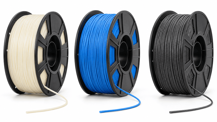
PLA filament is a polylactic acid (PLA) feedstock for fused deposition modeling (FDM) 3D printing. Its relatively low warping makes it useful for visual prototypes, fit checks and some indoor fixtures. Functional use depends on the exact formulation, print orientation, layer bonding, temperature and duration of loading. A clean print does not demonstrate a safe load limit. Compare grade-specific test data with the part’s operating conditions and verify critical features on the finished print.
1. What Is PLA Filament?
PLA filament is a continuous thermoplastic feedstock made primarily from polylactic acid, a polyester produced from lactic acid-derived building blocks. Its raw materials can come from renewable agricultural sources, including corn starch and sugarcane.
In FDM printing, the printer feeds the filament into a heated nozzle. The polymer softens and flows through the nozzle, forming deposited roads that cool and bond to previous layers.
PLA typically warps less than ABS during desktop FDM printing. That helps with fit-check models, but does not establish part strength or dimensional stability under service loads.
1.1. PLA Polymer Chemistry and Filament Composition
The base polymer is polylactic acid, but its molecular structure and formulation matter. The proportion of different lactic acid stereoisomers, molecular weight, and crystallinity influence how PLA melts, solidifies, and responds to heat.
A filament manufacturer may modify the polymer formulation to improve toughness, processing behavior, appearance, or thermal response. These changes do not necessarily improve every property. A tougher formulation, for example, should not be assumed to have higher tensile stiffness or better heat resistance.
Keep the resin, manufactured filament and printed part separate when evaluating PLA material properties. ISO/ASTM 52903-1:2020 covers material-extrusion feedstock identification, specification and traceability; it does not supply universal PLA strength or nozzle temperatures.
A wider comparison of 3D printer filament types helps distinguish PLA from the other polymer families before selecting a specific grade.
1.2. PLA vs PLA+: Additives, Blends, and Grade Differences
PLA+ is a commercial product designation, not a single standardized PLA grade. Its composition varies by manufacturer. One PLA+ filament may emphasize impact resistance, while another may be formulated for easier extrusion or reduced brittleness.
The same qualification applies to tough PLA, silk PLA, matte PLA, and fiber-filled PLA. These names describe product categories or intended characteristics, not guaranteed mechanical performance.
Adding fibers or mineral fillers can change stiffness, surface appearance, abrasion behavior, and processing requirements. Some filled formulations may require a wear-resistant nozzle. Their tensile strength, layer adhesion, and elongation still need to be evaluated using data for the specific grade.
When comparing PLA and PLA+, check the supplier’s material identification, technical data sheet, test methods, and specimen preparation conditions. A higher advertised strength value is not meaningful when the two results come from different specimen geometries or manufacturing conditions.
Choose a PLA or PLA+ grade from its required properties and documented testing, not the plus sign on the spool.
2. PLA Filament Properties and Mechanical Limits
PLA can produce stiff printed parts, but stiffness does not establish how much load a finished component can carry. Tensile strength, flexural strength, elongation, and long-term deformation describe different behaviors.
Published PLA properties also depend on the material grade and specimen manufacturing method. A value measured on an injection-molded specimen cannot be applied directly to an FDM part with printed layers, internal voids, and a different loading direction.
Start with the failure mode that matters: tensile rupture, deflection, brittle fracture or creep. Then check whether the reported specimen and test conditions represent the part.
2.1. Tensile Strength, Modulus, and Print Orientation
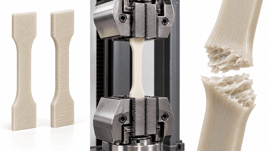
PLA tensile strength describes the maximum nominal tensile stress reached during a specified test. Tensile modulus describes stiffness in the measured stress-strain region. Elongation at break indicates how much the specimen extends before fracture.
ASTM D638-22 provides a method for measuring plastic tensile properties. Results depend on specimen geometry, conditioning, test speed, and strain measurement. For FDM specimens, the build orientation, raster arrangement, layer height, and infill configuration also need to be documented.
You cannot establish a printed bracket’s allowable load from a filament tensile strength figure alone. The load path, wall geometry, print orientation, and failure location must also be considered.
The stress calculations and orientation limitations documented in tensile testing of 3D printed parts are relevant when a printed bracket carries a directional load.
2.2. Flexural Properties and Long-Term Creep
A PLA housing tab, bracket, or cantilever often experiences bending rather than pure tension. The modulus of elasticity describes material stiffness, while bracket geometry, loading direction and support conditions determine actual part deflection
ASTM D790-25 measures flexural properties using a supported specimen loaded at its center. The reported flexural stress and modulus depend on specimen dimensions, support span, loading rate, and the calculation procedure. Procedure A and Procedure B use different strain rates, so their results should not be treated as directly interchangeable.
For printed PLA, the orientation of the layers relative to the bending load also matters. The surface under tension may expose layer interfaces or deposited roads to different stresses. A flexural value from a flat-printed coupon does not automatically represent an upright-printed bracket.
Short-term flexural tests also do not establish resistance to sustained loading.
PLA creep reflects its viscoelastic behavior. Under a constant load, a part may continue deforming with time. Temperature, stress level, geometry, and material formulation influence this creep response. A snap-fit held in continuous deflection can gradually lose retaining force, even without visible cracking.
A room-temperature tensile or flexural test does not establish how a PLA part will creep under a constant load for months. Verify time-dependent deformation at the relevant stress and temperature.
3. PLA Heat Resistance: Glass Transition, Melting Point, and HDT
PLA can lose stiffness and change shape well before it melts. For a printed housing, mounting bracket, or fixture, this matters more than the melting temperature alone.
3.1. Why Tg, Tm, and HDT Are Different
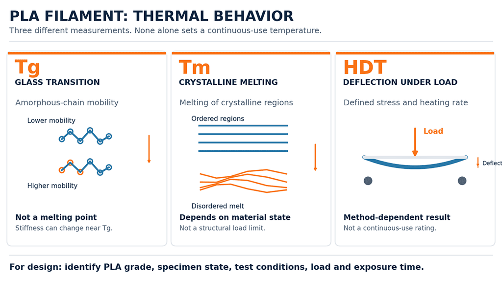
PLA thermal properties require three distinct measurements: glass transition temperature, melting temperature and heat deflection temperature. They answer different engineering questions.
| Property | What it describes | Engineering meaning |
| Glass transition temperature (Tg) | Temperature region where the amorphous polymer phase becomes more mobile | Stiffness and deformation behavior can change significantly |
| Melting temperature (Tm) | Melting of crystalline regions in a semicrystalline PLA formulation | Does not define the maximum temperature at which a printed part can carry a load |
| Heat deflection temperature (HDT) | Temperature at which a specimen reaches a specified deflection under defined bending stress and heating conditions | Useful for comparing short-term deformation under standardized test conditions |
For broader material selection, polymer heat resistance must be evaluated alongside loading conditions, dimensional stability and the manufacturing method used to produce the test specimen.
ISO 75-1:2020 establishes the general method for measuring deflection temperature under load. For plastics, ISO 75-2 provides the applicable specimen and test-condition details.
An HDT result needs its test method, applied flexural stress, specimen dimensions, preparation, and conditioning. A value reported without these details is difficult to compare with another supplier’s data.
HDT is not a continuous-use temperature rating. A PLA component can deform under sustained loading at temperatures below its reported HDT, particularly when the load creates continuous bending stress.
An electronics enclosure can be warmer near a regulator or other heat source than the surrounding room. Check temperature at stressed mounting features rather than relying on ambient temperature.
3.2. Annealing, Crystallinity, and Dimensional Stability
Annealing can change the crystalline structure of suitable PLA formulations. Depending on the grade and processing conditions, increased crystallinity may improve resistance to deformation at elevated temperatures.
The trade-off is dimensional change. Heating a printed part can release residual stresses, cause shrinkage, or distort unsupported features. Mounting holes, mating surfaces, and snap-fit dimensions may no longer meet their original tolerances.
ISO 75-1:2020 requires relevant specimen preparation and annealing conditions to be reported. HDT data obtained from annealed specimens cannot automatically be assigned to the same formulation in its as-printed state.
Check dimensions after any annealing treatment on representative printed geometry. Better thermal stability cannot compensate for holes or snap fits that no longer meet the drawing.
4. PLA Print Settings and Printability
PLA is generally easier to print than ABS because it tends to warp less and does not usually require a heated build chamber. That makes it practical for prototypes and small production fixtures. Reliable extrusion, however, does not guarantee a mechanically sound part.
4.1. Nozzle Temperature, Print Speed, and Layer Bonding
PLA printing temperature and print speed must follow the selected filament grade and the actual machine flow rate. Start with the manufacturer’s recommended nozzle and bed ranges, then inspect extrusion and layer adhesion at the intended speed.
For a functional part, record the linked process variables rather than treating each setting as an independent recipe:
- Nozzle temperature and extrusion rate: Look for continuous deposited roads without gaps, severe stringing, or visible degradation.
- Layer height and road overlap: Check whether adjacent roads and layers form continuous material across critical sections.
- Build orientation: Position the part with its principal service loads and critical dimensions in mind.
- Cooling and feature size: Inspect overhangs, thin walls, and small features without sacrificing required layer bonding.
A successful first print establishes a usable process starting point. Mechanical acceptance still requires appropriate testing or inspection.
4.2. Moisture, Storage, Warping, and Common Defects
PLA filament moisture, diameter variation and contamination can change extrusion behavior. Inspect packaging and feeding consistency before treating a printing defect as a slicer problem.
ISO/ASTM 52903-1:2020 addresses material-extrusion feedstock specifications, including filament characteristics and moisture-controlled packaging when required. It also calls for manufacturer-recommended storage conditions. The standard does not prescribe one universal PLA drying temperature or duration.
Follow the specific supplier’s handling instructions. Unnecessary or excessive heating during drying can deform filament or cause winding problems on the spool.
When printed PLA develops defects, identify the symptom before changing several settings at once.
| Observed problem | Factors to investigate | What to verify |
| Stringing between features | Nozzle temperature, retraction, travel behavior, filament condition | String formation and material deposits on finished surfaces |
| Weak layer bonding | Extrusion temperature, material flow, cooling, build orientation | Gaps, fracture location, and strength of critical features |
| Corners lifting from the bed | Bed adhesion, first-layer setup, cooling, part geometry | Flatness and distortion at mounting surfaces |
| Uneven extrusion | Filament diameter variation, feeding resistance, nozzle condition, moisture | Road continuity and dimensional consistency |
| Poor fit after printing | Shrinkage, orientation, process variation, feature geometry | Actual hole spacing, slot width, and mating dimensions |
Warping deserves particular attention on brackets, housings, and mounting plates. A part may look acceptable from above while its mounting face no longer sits flat.
Record the grade, lot and approved print setup for repeat work; inspect mating surfaces and loaded features as well as appearance.
Printer capability, accepted material grades and process repeatability must be defined before functional PLA production.
5. PLA vs PLA+, PETG, and ABS: Which Fits the Part?
PETG is often considered when a part needs greater ductility or improved temperature performance compared with general-purpose PLA. ABS may be more appropriate for applications requiring higher temperature resistance and impact performance, provided the printing process can control shrinkage and warping.
These are screening tendencies, not guaranteed material rankings. Select from named product grades with comparable test evidence.
| Selection factor | General-purpose PLA | PLA+ | PETG | ABS |
| Printing behavior | Generally easy to print with relatively low warping | Depends on formulation | Usually manageable, but stringing and adhesion need attention | More sensitive to shrinkage and warping |
| Stiffness | Grade dependent; check tensile or flexural modulus at the test temperature | No standardized PLA+ property; compare a specified supplier formulation | Grade dependent; compare actual stiffness and ductility data | Grade and temperature dependent; use comparable test data |
| Impact and fracture behavior | Can fracture with limited deformation | Some grades improve toughness | Often offers greater ductility than standard PLA | Commonly selected for tougher functional applications |
| Elevated-temperature use | Short-term room-temperature applications; verify loaded dimensions | Require grade-specific HDT and loaded-part testing | Consider for warmer duty, subject to grade-specific validation | Consider for warmer duty when warping and process controls are acceptable |
| Typical selection | Visual models, fit checks, low-load fixtures | Prototypes needing specified modified properties | Functional housings, brackets, and clips requiring ductility | Enclosures and functional parts with greater thermal demands |
Standard PLA may meet an indoor assembly fit check without introducing the process changes associated with PETG or ABS. For applications requiring a different balance of toughness, moisture response and thermal behavior, nylon mechanical properties provide another material-selection reference, although machined nylon data cannot be transferred directly to FDM nylon parts
A bracket carrying sustained load near a heat source presents a different decision. Its operating temperature, load duration, mounting geometry, and allowable deformation may justify testing PETG, ABS, or another engineering polymer instead.
Before switching materials, compare the specific product grades using equivalent test methods and representative printing conditions. Check tensile behavior, bending response, heat deflection, and the finished part’s dimensional stability where those properties affect the application.
6. Where PLA Works and Where It Needs Verification
Compare the expected duty with the part geometry. A brief screw-hole alignment check needs less evidence than a bracket carrying load for six months.
| Application | PLA selection judgment | What needs checking |
| Visual and presentation prototypes | Generally suitable | Appearance, dimensional accuracy, surface quality |
| Assembly and fit-check models | Generally suitable for room-temperature evaluation | Hole spacing, mating features, shrinkage, and flatness |
| Consumer electronics enclosure prototypes | Suitable for fit and appearance checks; functional use needs verification | Internal component temperatures, mounting features, screw loads, and ventilation |
| Indoor positioning fixtures | Suitable for light-duty applications when verified | Fixture stiffness, repeated handling, mounting accuracy, and expected service life |
| Cable-routing brackets and retaining clips | Requires part-level verification | Load direction, root geometry, layer bonding, repeated loading, and permanent deformation |
| Snap-fit features under sustained deflection | Requires particular caution | Creep, loss of retention force, repeated assembly, and fracture |
| Brackets near motors, heaters, or warm equipment | Generally avoid standard PLA without application-specific thermal validation | Local operating temperature, loading duration, and deformation |
| Outdoor or safety-critical structural components | Standard PLA is generally a poor default choice | UV exposure, weathering, temperature cycling, structural loads, and qualification requirements |
For a consumer electronics enclosure, PLA may be sufficient for checking PCB clearance, connector positions, button travel, and assembly access. Those checks do not establish suitability for the final operating environment.
A completed enclosure also sees heat from electronics, compression around screws and prolonged snap-fit stress. Consumer electronics enclosure prototyping should therefore verify temperature and critical mounting features before material approval.
Fixture design requires similar care. A positioning block used briefly at room temperature may have modest material demands. A cantilevered bracket supporting a continuous load needs additional attention to bending stress, layer orientation, and creep.
Rapid prototyping for PLA fit and form checks can confirm mounting geometry early. A root fillet and suitable print orientation may improve a loaded bracket, but they do not replace the relevant acceptance test.
Geometry and orientation deserve attention early: DFM guidelines for functional prototype geometry address wall sections and mounting interfaces, while rapid prototyping for PLA fit and form checks is suited to early assembly verification.
PLA should be selected because it meets the actual service requirements, not simply because it is convenient to print.
7. PLA Filament Specifications and Part Acceptance
A spool labeled PLA is not a complete purchasing specification. The filament grade, dimensions, composition, handling requirements, and lot identification need to match the intended printing process.
7.1. Filament Identity, Specifications, and Lot Traceability
Specify the actual filament grade, not just PLA plastic, on the purchasing document. The PLA material data sheet provides a reference for material identification, applicable property verification and the limitations of FDM part performance.
| Specification item | Information to request or verify | Why it matters |
| Material identity | Polymer designation, filament product, and supplier | Distinguishes one PLA formulation from another |
| Composition | Declared additives, fillers, and reinforcement where specified | Changes in formulation may affect printing and part performance |
| Filament geometry | Nominal diameter, specified tolerance, and machine compatibility | Diameter variation affects material delivery and extrusion consistency |
| Spool characteristics | Quantity, spool dimensions, and feeding compatibility | Helps prevent handling and feed-system problems |
| Lot traceability | Lot number, manufacture date, and unique spool or container identification | Links the received material to printing and inspection records |
| Packaging and storage | Packaging condition and manufacturer-recommended storage requirements | Helps maintain the specified feedstock condition |
| Conformity documents | Applicable specification and certificate of conformance when required | Provides documented evidence of conformity to specified requirements |
ISO/ASTM 52903-1:2020 addresses these feedstock controls, including identification and documentation requirements. Filament geometry must be evaluated against the applicable machine specification. The standard does not prescribe a single diameter tolerance for every PLA product.
A certificate of conformance confirms conformity to the stated requirements. It does not automatically provide measured tensile strength, heat deflection temperature, or moisture content.
7.2. Receiving Inspection and Printed-Part Acceptance
Receiving inspection should focus on the requirements that affect feeding, process consistency, and traceability.
Check the filament identification against the purchase order. Record the lot number, inspect the packaging condition, and verify dimensional requirements using the agreed inspection method.
Part acceptance is a separate activity.
Define acceptance against the part’s function, with measurement methods specified for critical features:
- Dimensions: Check mounting holes, mating features, flatness, and other critical dimensions against the drawing.
- Mechanical function: Apply the specified load and duration using a defined fixture and inspection procedure.
- Thermal exposure: Verify dimensions and function after exposure to the specified temperature and duration where relevant.
- Visible defects: Inspect critical sections for cracks, separation between layers, and unacceptable surface defects.
- Traceability: Link accepted components to their filament lot and approved printing conditions.
These checks are application-specific acceptance requirements, not universal limits imposed by ISO/ASTM 52903-1.
Define mounting-hole spacing, slot width and flatness using manufacturing tolerances and inspection standards. Record material identity separately from finished-part acceptance.
Approve the feedstock specification and printed-part inspection plan together. The verified additive manufacturing FDM process determines which printer capabilities and controls apply.
8. PLA Engineering Case: An Indoor Cable-Routing Bracket
An L-shaped PLA bracket provides a useful example of why filament properties and finished-part acceptance must be evaluated separately.
The supplied PLA cable-routing bracket dataset specifies an 80 × 35 × 28 mm indoor electronics fixture for a 6 mm cable bundle. Design duty is an intermittent pull up to 12 N at 20 to 28°C over six months. The source labels the test plan and results illustrative, so the figures below are documented case inputs, not independently verified production or certified test evidence.
The bracket has a 5 mm thick base and upright, with an R5 mm inside fillet. Two M5 screws secure the base.
8.1. Material, Print Orientation, and Test Results
The specified material was unfilled, natural PLA filament with a nominal diameter of 1.75 ± 0.03 mm. The supplier and exact grade were not recorded.
| Item | Supplied illustrative case figures, not independently verified test results |
| Nozzle / bed temperature | 205°C / 60°C |
| Layer height | 0.20 mm |
| Perimeters / infill | 4 perimeters / 40% gyroid |
| Build orientation | Base flat on XY bed, upright built along Z |
| Tensile strength | 42.8 MPa mean, n = 5 XY coupons |
| Tensile modulus | 2,700 MPa mean |
| Flexural strength | 72 MPa mean, n = 5 |
| Flexural modulus | 2,850 MPa mean |
| HDT | 52°C mean, 1.80 MPa test stress, n = 3 |
The provided dataset references ISO 527-1/527-2, ISO 178 and ISO 75-2 as test frameworks. It explicitly identifies the test plan and results as illustrative, without certified conformity; no material manufacturer or exact PLA grade is documented. Treat the results as bounded case data rather than a transferable PLA materials specification.
The base-flat orientation supports mounting accuracy, but the pulling load bends the upright at its root. This places stress across the printed layer interfaces near the fillet.
8.2. Part Acceptance and Failure Boundary
The case specifies a 30 N static pull held for 60 seconds, with no fracture and no more than 0.5 mm permanent slot opening.
All five brackets in the supplied illustrative dataset met these criteria. Residual slot opening ranged from 0.10 to 0.22 mm.
In the supplied dataset, 10 of 10 brackets meet the specified dimensions. Following 40°C unloaded exposure for 24 hours, the greatest individual mounting-hole-spacing change is 0.09 mm against a 0.4 mm limit. These checks do not measure deformation under load at 40°C.
During exploratory overload at 46 to 55 N, cracking developed near the upright root, followed by visible interlayer separation.
Within the case dataset, the bracket meets the stated indoor, non-safety-critical acceptance conditions. That limited conclusion does not establish six-month creep life. PETG was considered for greater ductility and thermal margin, but the documented short tests alone do not establish comparative lifetime reliability.
9. Frequently Asked Questions About PLA Filament
9.1. Is PLA Filament Strong Enough for Functional Parts?
PLA can be used for functional parts when the selected grade, geometry, loading direction, and service conditions are suitable. A tensile strength value alone does not establish the load capacity of a printed bracket. Critical parts need verification of layer bonding, dimensions, and actual loading conditions.
9.2. What Is the Difference Between PLA and PLA+?
PLA+ is a commercial designation for modified PLA filament, not a standardized material grade. Formulations vary by manufacturer. Compare specific products using their technical data sheets and equivalent test conditions rather than assuming every PLA+ filament is stronger or more heat-resistant.
9.3. Can PLA Filament Withstand High Temperatures?
General-purpose PLA has limited resistance to deformation at elevated temperatures, particularly under sustained loading. The relevant limits depend on formulation, crystallinity, stress, and exposure time. Check grade-specific HDT data and validate the finished component under its intended operating conditions.
9.4. Does PLA Filament Need to Be Dried Before Printing?
Not every PLA spool requires the same drying treatment. Check the manufacturer’s storage and conditioning instructions, packaging condition, and observed extrusion behavior. Excessive drying temperatures can deform filament. ISO/ASTM 52903-1:2020 does not prescribe a universal PLA drying schedule.
9.5. Is PLA Filament Biodegradable and Compostable?
PLA can biodegrade under suitable controlled conditions, but that does not mean a printed PLA part will readily decompose outdoors or in home compost. Compostability depends on the formulation, finished product, and disposal conditions. A renewable raw-material source is not evidence that every PLA filament meets a compostability certification.
A PLA purchase specification should identify the grade and acceptance tests, while the drawing and print record define what the finished part must achieve. A supplier material data sheet and a short coupon test do not replace a loaded-part test where failure matters.
Ready to Quote Your CNC Prototype?
Upload your STEP file and get a DFM review + quote within 12 hours.
No tooling cost. Minimum 1 part.
