

Dewey Wu General Manager & senior mechanical engineer at EPOC CRAFTER, 15 years in design engineering, quality, and metallurgy. Hands-on across CNC machining, metalwork, sheet metal, and prototyping (subtractive + 3D printing).
TIG welding is gas tungsten arc welding, or GTAW. It uses a nonconsumable tungsten electrode to create the arc while shielding gas protects the weld pool. Filler metal can be added separately, or the joint can be welded autogenously when the qualified procedure allows it. For engineers and buyers, the TIG welding process is only one part of the decision. Material, joint preparation, TIG welding parameters, welding distortion, inspection, and machining after welding can all affect the final part. This guide explains what is TIG welding, where it fits, what the standards control, and when datum recovery and finish machining are needed.
1. TIG Welding Definition and Process
The TIG welding definition is straightforward. TIG stands for tungsten inert gas, while GTAW means gas tungsten arc welding. What is GTAW welding? It is the American terminology for the same process family. An electric arc forms between the workpiece and a nonconsumable tungsten electrode. Shielding gas isolates the hot electrode and weld pool from the atmosphere. In American terminology, gas tungsten arc welding and GTAW welding refer to the same process family. Tungsten inert gas welding is the expanded form behind the acronym TIG.
ISO 4063:2023 places TIG in process group 14, gas shielded arc welding with a nonconsumable tungsten electrode. Process 141 is TIG welding with solid filler material. Process 142 is autogenous TIG welding, where no filler metal is added. The process number identifies the welding method. It does not set current, voltage, shielding gas flow, heat input, distortion allowance, or final tolerance.
1.1 How Does TIG Welding Work? Equipment and Arc Control
Basic TIG welding equipment includes a TIG welding machine, TIG welding power source, TIG welding torch, tungsten electrode, shielding gas supply, work connection, and controls. A TIG welding setup adds a TIG filler rod or TIG welding filler rod when the procedure requires filler. The TIG welding electrode carries current to the arc but is not the normal source of deposited weld metal.
A TIG welder can control arc heat independently from filler addition. That is one reason the process works well when the joint needs controlled heat placement, a small weld pool, or careful access. It does not mean the process will hold a final bore location or mounting face flatness by itself. Weld sequence, restraint, section stiffness, joint position, and later machining still matter.
2. TIG Welding Applications and Process Selection
TIG welding applications cover thin sheet, tubing, machined weldments, pipe, stainless steel assemblies, aluminum structures, and components that need close control around the weld. What metals can TIG weld? Common production applications include steels, stainless steels, aluminum alloys, titanium, nickel alloys, and copper alloys when the procedure fits the material. What is TIG welding good for? These TIG welding uses include work where arc placement, heat control, joint access, or visible bead control matter more than high deposition rate. When to use TIG welding becomes a part specific decision once section thickness, fit up, production rate, and inspection enter the RFQ. Why use TIG welding here? Use it when that added arc and filler control solves a real joint requirement. The procedure should still follow the part instead of a generic settings chart.
For TIG welding stainless steel, the grade, filler, shielding, heat tint control, and corrosion requirements need to stay aligned. The EPOC CRAFTER 316L stainless steel guide explains why low carbon content matters after thermal exposure.
For TIG welding aluminum, current type, oxide control, filler choice, and section thickness change the procedure. Titanium TIG work demands strong atmospheric protection while the weld and adjacent hot metal remain reactive. Steel work needs filler and thermal controls that match the grade and procedure. TIG welding pipe adds joint fit, root access, and backing gas questions. TIG welding sheet metal places more emphasis on warpage and local heat concentration. Aerospace work can require tighter procedure control and traceability, but the industry label alone never sets the welding variables.
EPOC CRAFTER TIG welding sheet metal fabrication is a useful next step when the part combines TIG welding sheet metal with formed features and post weld inspection.
2.1 TIG vs MIG Welding
MIG vs TIG welding is a process selection question, not a ranking. ISO 4063 places MIG and MAG in group 13 and TIG in group 14. MIG uses a consumable wire electrode. TIG uses a nonconsumable tungsten electrode and can add filler separately.
Table 1. TIG vs MIG welding decision table
| Decision | TIG welding | MIG welding | Manufacturing implication |
| Electrode and filler | Nonconsumable tungsten with separate filler or no filler | Consumable wire is the electrode and filler | TIG separates arc control from filler addition |
| Thin or localized work | Strong control over a small arc and weld pool | Can be used with suitable transfer mode and settings | TIG often suits thin or heat sensitive features |
| Deposition and pace | Lower deposition rate in conventional manual TIG | Continuous wire feed supports higher deposition | MIG often shortens weld time on longer or heavier joints |
| Fit up and operator control | Demands close control of arc length, travel, filler, and fit up | More process variables are coupled through wire feed and voltage | TIG asks more from the welder or automation package |
| Post weld machining | May still be required | May still be required | Process choice does not remove datum movement or weldment distortion |
Process identity is based on ISO 4063:2023. Electrode, filler, control, and relative process pace are consistent with TWI process guidance. The table does not claim that one process always produces a stronger weld.
TIG vs MIG and TIG vs MIG welding lead to the same engineering check: material, joint geometry, required weld quality, production rate, and final geometry. TIG welding advantages include independent filler control and concentrated arc control. Those benefits matter less when a high deposition rate dominates the job. Other process comparisons need the same context because equipment, access, fit, and thermal profile change with the process.
3. TIG Welding Parameters, Gas, and Filler
TIG welding settings are procedure variables, not universal recipes. TIG welding current, TIG welding polarity, travel speed, shielding gas, filler, preheat, interpass temperature, and welding heat input interact with material, thickness, joint geometry, and position. Any published TIG welding parameters should state those conditions.
3.1 Current, Polarity, and Heat Input in Welding
ISO 4063 identifies the process but does not prescribe TIG welding current or TIG welding polarity. ISO 15614-1 procedure qualification records current, voltage, travel speed, and heat input. That distinction matters when heat input in welding is linked to distortion. A lower current does not guarantee less warpage if travel slows, pass count rises, or restraint changes.
The EPOC CRAFTER 4130 case later in this article used DCEN, 95 A, 11.5 V, 110 mm/min travel speed, two passes, 150 °C preheat, and a 200 °C maximum interpass temperature. Those values are MEASURED project data. They are not a TIG welding settings table for other 4130 parts.
3.2 TIG Welding Gas and Shielding Gas
ISO 14175:2008 classifies welding gases by composition. For the inert group used in many TIG procedures, I1 is argon, I2 is helium, and I3 covers argon helium mixtures with 0.5 to 95 vol.% helium. A specific I3 gas still needs its nominal composition because I3 is a family, not one fixed blend.
TIG welding argon is common because argon is an inert shielding gas and supports stable arc operation across many materials. TIG welding shielding gas selection still belongs to the procedure. ISO 14175 classifies the gas. It does not prescribe gas flow, cup size, purge time, current, voltage, penetration, or distortion.
3.3 Filler Metal and Autogenous TIG Welding
Process 141 uses solid filler material. Process 142 is autogenous TIG welding. A TIG filler rod changes deposited chemistry and joint fill, so the filler classification must match the material, joint, service, and qualification basis. A TIG welding filler rod cannot be selected from a generic chart without those inputs.
Autogenous TIG welding can be valid when the joint design and procedure support it. Removing the filler rod from a qualified 141 procedure does not automatically create an acceptable 142 procedure.
4. Joint Preparation, WPS, PQR, and WPQR
Weld joint preparation and procedure qualification are where a drawing becomes a controlled manufacturing route. The joint geometry sets access and fusion conditions. The welding procedure specification defines the production variables. The qualification record shows which range has been demonstrated.
4.1 Weld Bevel and Welding Joint Preparation
ISO 9692-1:2013 covers steel joint preparation for processes that include TIG 141. It contains square, V, bevel, U, J, and double sided preparations with conditions for thickness, groove angle, root gap, root face, backing, and back run.
One single V entry that includes 141 covers material thickness above 3 mm through 10 mm, an included angle of 40° to 60°, root gap below 4 mm, and root face up to 2 mm. Other preparation types use different values. A weld bevel is therefore a geometry choice with defined conditions, not one universal TIG dimension.
4.2 Welding Procedure Specification and Qualification
A welding procedure specification, or WPS, is the production instruction. ISO 15614-1:2017 with Amendment 1:2019 qualifies the procedure through a test piece and documented results. The sequence is pWPS, procedure test, examination and testing, qualification range, WPQR, then production WPS.
In RFQs, the phrase PQR welding is still common, but ISO 15614-1 uses WPQR for Welding Procedure Qualification Record. The WPS is the production instruction, while the WPQR records the procedure test, results, and qualified range. Welding procedure qualification does not certify final part geometry.
For an RFQ, you should separate three requirement groups.
Table 2. What each requirement controls
| Requirement | What to specify | Why it matters |
| Weld process | Process number, joint type, filler, gas, WPS, qualification basis, weld acceptance | Controls how the joint is produced and accepted |
| As welded geometry | Weldment dimensions, broad flatness or angular limits, applicable welding tolerance | Controls whether the fabrication can move to the next operation |
| Final machined CTQs | Datum scheme, bore fit, position, flatness, parallelism, Ra | Controls assembly and function after finish machining |
The process and qualification boundaries are based on ISO 4063:2023, ISO 15614-1:2017 plus Amd 1:2019, and ISO 13920:2023.
5. Heat Input, Welding Distortion, and Welding Tolerance
Welding distortion comes from nonuniform heating and cooling around the joint. The resulting welding deformation can show up as angular change, bowing, loss of flatness, loss of parallelism, datum shift, bore movement, or full weldment distortion. Heat input is one contributor, not a complete predictor.
Welding distortion control starts with part geometry, tack pattern, fixture restraint, weld sequence, bead placement, and clamp release. Weld residual stress can also affect later stability, so the process plan should not assume that a part held in position during welding will stay there after release.
ISO 13920:2023 covers general tolerances for welded constructions. It uses classes A through D for linear and angular dimensions and E through H for straightness, flatness, and parallelism. That welding tolerance framework is useful for as welded fabrication, but it does not replace individually specified final CNC tolerances or a datum reference frame.
The EPOC CRAFTER welding tolerance and datum standards provides a broader drawing context for general tolerances and feature specific controls.
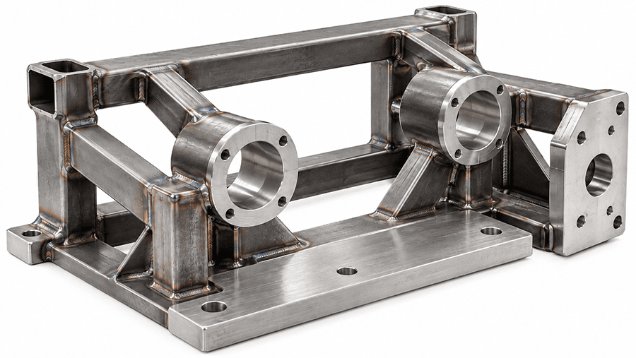
6. Machining After Welding and Datum Recovery
Machining after welding is useful when the final function depends on features that can move during the thermal cycle. That includes bearing bores, locating holes, mounting pads, guide faces, sealing faces, and precision datums. Post weld machining is a planned process step when it is built into the route from the start.
6.1 Machining Stock and Datum Machining
No standard in this article gives one universal stock allowance for weldment machining. You set stock from the expected movement, feature geometry, setup access, cutting process, and final tolerance.
The EPOC CRAFTER case left 1.5 mm on the critical face and 1.0 mm on the bore and hole features before welding. After welding, the finished lower mounting pad was skimmed first and became Datum A. The team then probed datum targets, established the work offset, finished the opposite pad, line bored the Ø35 bearing pair, and finished the locating holes and motor face.
This is datum machining in a practical sense. The final machining datum is established from the welded condition, then the CTQs are generated from that reference. The EPOC CRAFTER tight tolerance finish machining guide shows why only function critical features should carry the tightest controls.
6.2 CNC Machining After Welding
CNC machining after welding should come after the weldment has reached the condition defined by the route. That may mean cooling, inspection, straightening, stress relief when specified, or another controlled step before metal removal. The route must state what applies.
For the case frame, machining after welding used two setups on a four axis VMC with a precision boring head. EPOC CRAFTER CNC machining after welding is relevant when the same welded assembly needs face finishing, boring, locating features, and final CMM inspection.
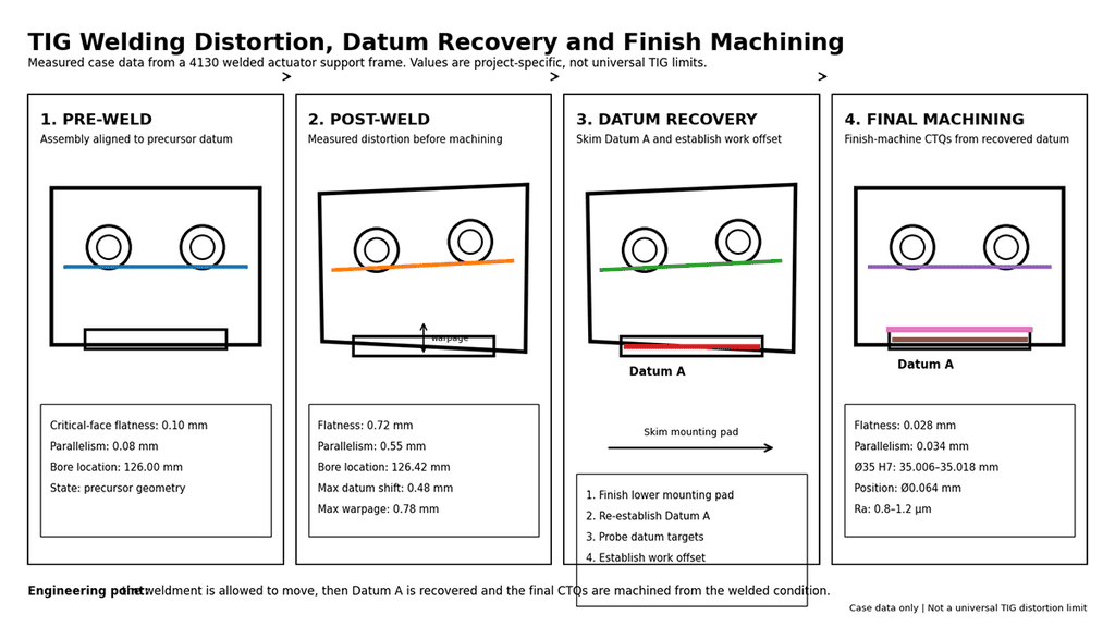
7. EPOC CRAFTER Production Case
The production case used 24 actuator support frames for industrial motion control equipment. Each assembly used AISI 4130 / UNS G41300 tube with machined bosses, 3.0 mm wall thickness, and an envelope of 420 × 260 × 180 mm. Functional features included Datum A, two Ø35 bearing bores, the motor mounting face, and a locating hole pattern.
The TIG welding fabrication route used ISO 4063 process 141 with AWS A5.28 ER80S-D2 filler, I1 argon shielding and backing gas, DCEN, and two passes. A modular steel fixture used hard stops, toggle clamps, and copper heat sinks. Twelve tack welds were placed at 35 to 50 mm spacing. Welding started at the center joints and moved outward in opposing pairs using alternating and backstep sequencing. Clamps were released after the weldment cooled below 60 °C.
Table 3. Measured geometry before and after welding
| Feature | Before welding | After welding before machining | Decision |
| Critical face flatness | 0.10 mm | 0.72 mm | Leave stock and create the final face after welding |
| Parallelism | 0.08 mm | 0.55 mm | Finish both functional pads from a recovered datum |
| Bore location from datum | 126.00 mm | 126.42 mm | Do not rely on the pre weld bore coordinate for final position |
| Maximum datum shift | N/A | 0.48 mm | Reestablish Datum A before boring |
| Maximum linear warpage | N/A | 0.78 mm | Inspect the weldment before finish machining |
EPOC CRAFTER production case, 24 inspected parts at 20 °C using CMM plus surface plate and dial indicator methods.
The final machining route recovered Datum A first, then generated the CTQs.
Table 4. Final CTQ results after finish machining
| CTQ | Drawing requirement | Measured result | Acceptance |
| Mounting face flatness | 0.05 mm | 0.028 mm | Pass |
| Parallelism | 0.05 mm | 0.034 mm | Pass |
| Bearing bore | Ø35 H7 | 35.006 to 35.018 mm | Pass |
| Feature position | Ø0.10 mm | Ø0.064 mm | Pass |
| Surface roughness | Ra 1.6 µm | Ra 0.8 to 1.2 µm | Pass |
EPOC CRAFTER production case. Twenty four parts were inspected. Twenty two passed the first machining attempt, two required a second skim because local high spots remained, and zero parts were rejected.
The bore moved 0.42 mm from its pre weld coordinate, but the final position result was Ø0.064 mm after datum recovery and line boring. Those numbers describe different measurement quantities, so they should not be subtracted as if they were the same characteristic.
The welding cycle was 38 min per assembly. Post weld finish machining was 54 min per assembly. Those real cycle times show why a precision welded assembly cannot be priced as a weld only operation when datum recovery, boring, face finishing, and inspection are part of the drawing.
The EPOC CRAFTER weldment DFM and datum design covers the drawing choices that should be resolved before welding starts. EPOC CRAFTER’s end-to-end manufacturing services cover integrated welding, machining, and inspection when one supplier manages the complete production route.
8. Inspection and TIG Welding Defects
TIG welding quality and final dimensional quality need separate acceptance checks. A weld can pass visual or penetrant inspection while the weldment still needs machining before the functional geometry is complete.
TIG welding defects can include TIG welding porosity, incomplete fusion, inadequate TIG weld penetration, undercut, overlap, cracking, and tungsten contamination. The inspection method and acceptance criteria must come from the drawing, contract, code, or qualified procedure. This article does not assign a universal defect limit.
In the production case, visual inspection accepted no cracks, incomplete fusion, overlap, or visible porosity, with undercut limited to 0.5 mm. PT found no relevant linear indications. Those are project acceptance criteria. They are separate from the final 0.05 mm flatness, 0.05 mm parallelism, Ø35 H7 bore, and Ø0.10 mm position requirements.
EPOC CRAFTER’s quality and certifications page outlines the quality management framework supporting fabrication and CNC machining inspection.

9. FAQ
9.1 What gas should I use for TIG welding?
Argon is a common TIG welding gas, but the correct TIG welding shielding gas depends on material and the qualified procedure. ISO 14175 identifies I1 as argon, I2 as helium, and I3 as argon helium mixtures. The standard classifies composition and gas quality. It does not set the flow rate for your joint.
9.2 Do you need filler while TIG welding?
No. Process 142 is autogenous TIG welding and uses no added filler. Process 141 uses solid filler material. You should use the process and filler condition defined by the joint design and qualified procedure. A no filler weld is not an automatic substitute for a filler qualified joint.
9.3 When would you use an autogenous TIG weld?
Use it only when the joint, material, fit up, required section, and procedure support fusion without added filler. Precision tubing and some close fit butt joints can use autogenous GTAW, but filler can be required for chemistry, joint fill, or mechanical reasons. The decision belongs in the TIG welding procedure.
9.4 Will welding change a bearing bore that was machined first?
It can. Welding heat and restraint can move or distort a bore even after the assembly cools. If the bearing fit or position is a CTQ, leave machining stock where practical and plan finish machining after welding. The case in this article recorded a 0.42 mm bore coordinate shift before the final line boring operation.
When you source TIG welding services for a precision weldment, review the full manufacturing route. Weldment fabrication becomes more complex when the drawing combines welds with bearing fits, mounting faces, locating patterns, or GD&T. Send the CAD model and drawing together so the welding procedure, machining stock, datum machining, and final inspection can be reviewed as one plan.
Ready to Quote Your CNC Prototype?
Upload your STEP file and get a DFM review + quote within 12 hours.
No tooling cost. Minimum 1 part.
