

Dewey Wu General Manager & senior mechanical engineer at EPOC CRAFTER, 15 years in design engineering, quality, and metallurgy. Hands-on across CNC machining, metalwork, sheet metal, and prototyping (subtractive + 3D printing).
Complex CNC machining is difficult when the required part features cannot be cut, held, or inspected through a straightforward process. Deep cavities restrict tool access, thin walls move under cutting and clamping loads, and positional controls across faces complicate datum transfer. Material condition, quantity, surface texture, and inspection scope change the process route and the resulting CNC machining cost.
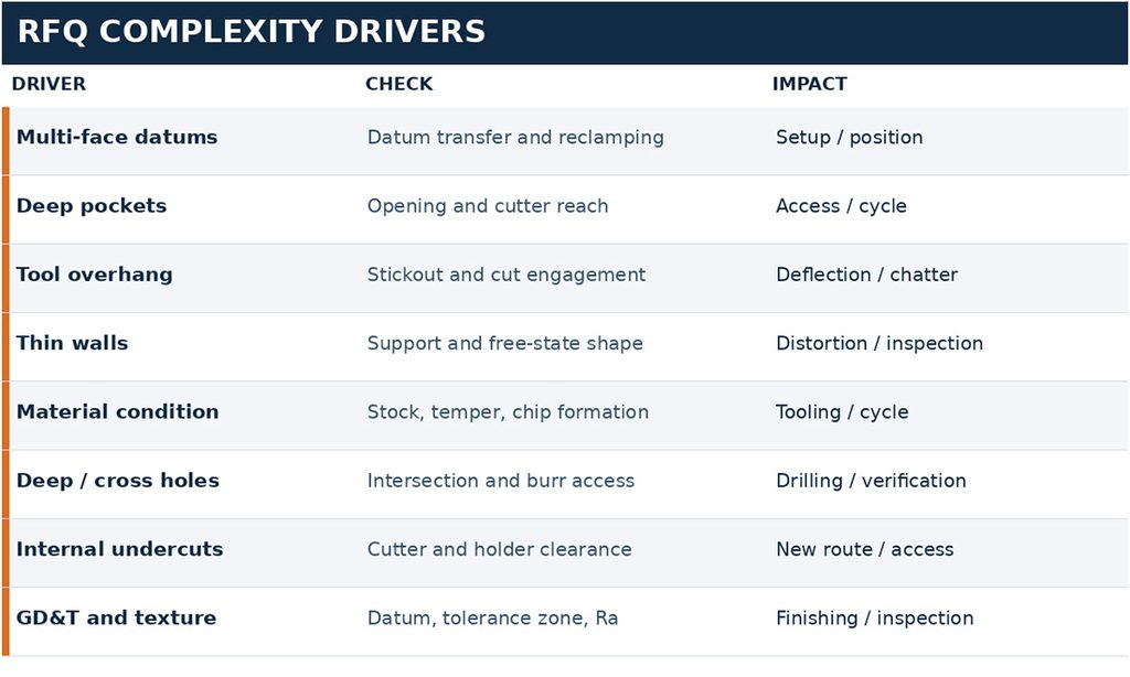
Use the eight-driver RFQ scorecard below to identify the constraint before comparing a CNC machining quote. It separates manufacturability questions from claims about price, cycle time, and finished-part acceptance.
1. How to Evaluate CNC Machining Complexity Before an RFQ
A complex machined part is not necessarily difficult because it has many features. The difficulty comes from how those features interact with the proposed manufacturing process.
A pocket accessible with a standard end mill may be straightforward. Add a deep side hole, a datum relationship across several faces, and tight positional tolerances, and the manufacturing route changes. The supplier may need additional workholding, a different machine configuration, or a revised inspection sequence.
Count the machining orientations and critical relationships, not just the CAD features.
1.1 The Eight Complexity Drivers
Screen the eight drivers against geometry, material condition, quantity, machining route, and inspection coverage. Each row identifies a question that can change the RFQ decision.
| Complexity driver | What engineers should check | Potential impact |
| Multi-face datums and setups | Datum relationships, orientations, repeated alignment | Additional setups, datum transfer, inspection |
| Deep pockets and cavities | Depth, opening width, tool entry, chip evacuation | Tool access, cutting time, surface quality |
| Long tool overhang | Tool diameter, unsupported length, cutting conditions | Deflection, chatter, dimensional variation |
| Thin walls | Thickness, unsupported height, clamping, material behavior | Distortion, rework, dimensional instability |
| Material machinability | Grade, condition, cutting response, tooling | Tool life, cutting parameters, cycle time |
| Deep and intersecting holes | Depth, diameter, intersection, internal access | Drilling, burr removal, inspection |
| Internal corners and undercuts | Cutter radius, approach, clearance | Tool selection, alternate route, setups |
| Tight tolerances and surface requirements | GD&T, texture, datum structure, verification | Finishing, measurement, rework |
These are engineering risk categories, not difficulty ratings prescribed by an ISO standard. ISO 1101:2017 describes geometrical tolerancing; ISO 5459:2024 covers datums and datum systems; ISO 21920-2:2021 defines profile surface texture parameters. They do not set machining price multipliers or universal RFQ scores.
1.2 A Practical RFQ Scoring Method
Classify each driver by whether a feasible manufacturing and verification route is already established. This first-pass screening is not a statistically validated cost model.
| Review level | Engineering meaning | RFQ action |
| Low | Accessible feature; established process and inspection method | Confirm the normal manufacturing route |
| Moderate | Additional planning, dedicated workholding or measurement attention | Review process and inspection plan |
| High | Important manufacturability or verification constraint unresolved | Resolve feasibility before comparing final quotations |
A single high-risk feature can dictate the route. Seven ordinary features do not cancel out an inaccessible eighth feature. Do not sum these labels into a quotation formula. Record the feature, risk mechanism, proposed route, inspection coverage and potential design remedy.
A supplier may classify one deep feature as moderate on a machine with adequate tool reach and another supplier may classify it as high because its available holders collide with the part. Record tool clearance, CNC fixturing limitations, the proposed measurement route, and unresolved assumptions before assigning the review level.
1.3 Real Production Case: Reducing Setup Complexity Without Changing the Part
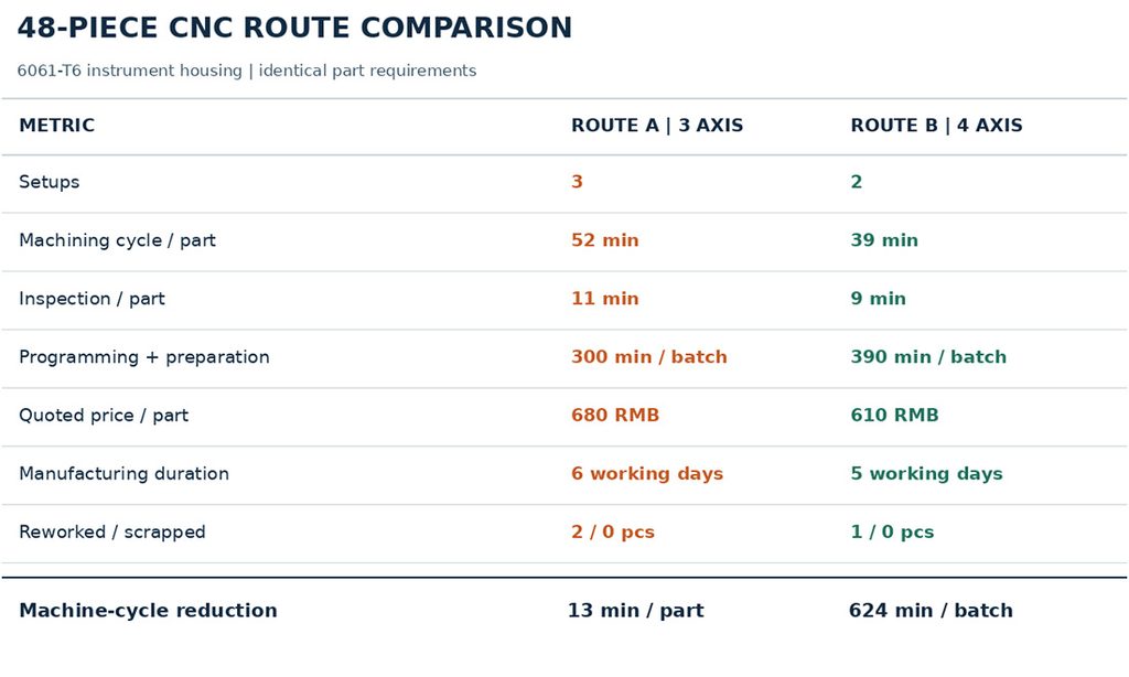
The following figures come from actual production and finished-part inspection data for a 48-piece batch of 6061-T6 aluminum instrument housings. The 120 × 80 × 30 mm housing carried a machined cavity, locating holes and a lateral passage. Both compared routes held the same geometry and critical acceptance requirements.
Route A used a three-axis vertical machining center and three setups. Route B used four-axis indexing and dedicated soft jaws to complete the work in two setups.
| Recorded result | Route A | Route B |
| Operations / setups | 4 / 3 | 3 / 2 |
| Batch programming and preparation | 300 min | 390 min |
| Machine cycle per part | 52 min | 39 min |
| Inspection time per part | 11 min | 9 min |
| Quoted unit price, 48 pcs | RMB 680 | RMB 610 |
| Manufacturing lead time | 6 working days | 5 working days |
| Rework / scrap | 2 / 0 | 1 / 0 |
The four-axis route saved 13 minutes of machine time per part, or 624 minutes across the batch. It required 90 additional minutes of programming and preparation. Inspection decreased by two minutes per part. Both routes met the same acceptance limits after rework. Route B did not achieve its lower quote by relaxing geometry or inspection.
For this batch, Route A recorded 2,496 minutes of machining and 528 minutes of inspection, versus 1,872 and 432 minutes for Route B. Adding recorded batch programming and preparation gives 3,324 minutes for Route A and 2,694 minutes for Route B. The difference is 630 minutes across 48 parts, excluding any labor or machine cost allocation not stated in the case data. At the quoted prices, the 48-part totals were RMB 32,640 and RMB 29,280. Those are quoted totals, not audited production costs.
Route B reduced the quoted unit price by RMB 70 for this 48-piece comparison. This is a batch-specific observation, not a universal discount for four-axis machining. Dedicated fixturing and indexing access must still justify their cost on the intended quantity.
2. Eight Drivers of Complex CNC Machining
For each feature, identify its physical constraint, likely process consequence, practical modification, and verification requirement. A risk rating without these details has little value.
Precision CNC machining is not a single difficulty tier. A complex machining decision depends on the controlled feature, its position relative to datums, and whether a proven cutter and inspection approach can reach it.
2.1 Multi-Face Datums and Additional Setups
A side hole can be easy to cut yet difficult to locate to features produced in another setup. Each release and reclamp changes how the workpiece contacts the fixture and how the machining coordinate system is restored. Datum reference frame requirements in a GD&T drawing describe the geometric relationship to be achieved, not a prescribed number of setups.
Ask which datum features can be established in the first operation, which surfaces are accessible after indexing, and how the location of critical holes will be verified. CNC workholding must locate the part without damaging contact surfaces or distorting a thin section. Multi axis machining can reduce transfers, but an indexing fixture that blocks cutter access solves little.
The datum reference frame controls how a feature is located for geometric tolerancing; it does not prescribe the number of machine setups. A datum system, the CNC workholding contact points, and the work offset must be reviewed as separate but related elements. Multi axis machining can preserve access across faces, provided indexing error, fixture rigidity, and probe strategy are acceptable.
In the real housing comparison, the 5 mm lateral hole was machined after an independent setup on Route A. Route B used indexing and soft jaws, reducing opportunities for independent realignment. That is a process difference, not evidence that every four-axis machine is more accurate.
The related thin wall aluminum CNC machining case shows why clamp release and feature geometry need their own inspection plan.
2.2 Deep Pockets and High Aspect Ratios
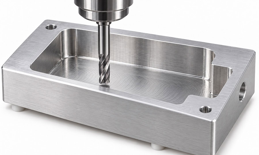
The issue with deep cavity milling is not simply cavity depth. A narrow opening may force a small-diameter tool to reach a deep floor, increase toolpath length, restrict coolant delivery or trap chips. A larger pocket with the same depth may accept a much stiffer cutter.
Record pocket depth, minimum entry width, inside radii, floor finish and obstructions above the machining plane. The example housing had a cavity 20 mm deep and 54 mm wide with a 5 mm remaining floor. Those dimensions do not by themselves establish a high-risk cavity. They must be read together with cutter reach, wall stability and clamp access.
Widening a nonfunctional opening, allowing a larger internal radius or permitting a separate access operation may simplify the route. Do not move a sealing face or weaken a load path merely to shorten the tool.
2.3 Tool Overhang, Deflection and Chatter
Tool overhang matters because cutting forces act on a less rigid tool when the unsupported length increases. Tool deflection can displace a finished wall; machining chatter can spoil finish, increase tool wear or force lighter cutting conditions. The response also depends on tool material, holder, engagement, spindle dynamics and workpiece stiffness.
The recorded housing setup had an 8 mm end mill with a maximum 45 mm overhang. The arithmetic length-to-diameter ratio is 45/8 = 5.625, approximately 5.63. This is a geometry descriptor, not an ISO limit or proof of chatter. Ask for actual holder clearance and the planned finishing approach before classifying risk.
Machining chatter is a dynamic response, not a direct measurement of static tool deflection. Review spindle speed, tooth engagement, cutter geometry, and holder stiffness separately. The 5.63 ratio in this case describes the reported tool overhang, not a certified cutting limit.
A shorter stickout, a larger tool diameter or changed feature access may improve stiffness. Altering feed or radial engagement may manage vibration, but a blanket numerical overhang cutoff is not credible across different tools and cuts.
2.4 Thin Walls and Part Distortion
Thin wall machining brings the fixture into the dimensional problem. Clamping may temporarily flatten a wall while cutting. The shape can change after release; thermal and residual-stress effects may contribute. Inspect free-state dimensions when the functional requirement applies to the unclamped part.
The housing had a local wall of 3.0 mm over an effective 20 mm height. Its 0.05 mm mounting-face flatness requirement belongs to the specified surface, not automatically to every wall or pocket floor. Confirm clamping direction, stock-removal sequence, support position and when measurement takes place.
A thin wall machining review should state whether the flatness tolerance applies in the free state and how the part is supported during dimensional inspection. A clamped measurement may conceal released-part movement. A tolerance stack up across the housing, sensors, and locating holes is a design check distinct from the flatness of a single surface.
Tight tolerance machining can be practical on a short, well supported bore while the same numerical tolerance may be expensive across a long, weak wall. State the feature and acceptance conditions instead of treating the adjective tight as a process capability.
2.5 Material Condition and Machinability
Machinability rating is not a universal difficulty ranking for completed parts. A material may be straightforward to cut but difficult to hold to a particular surface, bore or distortion limit. CNC machining materials must be identified by grade, condition and stock form before selecting tooling or claiming a cycle-time advantage.
The actual case used 6061-T6 aluminum from sawn extruded plate stock. The documented cutting concern was built-up edge and burr formation, managed using sharp, polished-edge carbide tooling; no unusual tool-wear rate was established. Compare that with titanium machining, stainless steel machining or Inconel machining only for defined grades and cutting conditions, not by asserting a fixed price hierarchy.
CNC machining material selection becomes important when stock form, temper, and chip behavior change the planned route.
Inconel machining, titanium machining, and stainless steel machining can create different tool wear, heat, and chip-control constraints. Hard machining usually refers to machining hardened materials, not to every difficult part. Compare the actual material grade and condition, rather than applying an unsupported universal machinability rating.
2.6 Deep Drilling and Intersecting Holes
A hole can have a nominal diameter that is simple to inspect at its entrance while the intersection, internal burr and full-depth geometry remain difficult to access. Deep hole drilling risk depends on diameter, depth, tool route, runout, evacuation and the required straightness or location. Cross hole drilling adds a burr and cleaning problem at the intersection.
The housing included a 5 mm blind lateral hole with 45 mm effective depth and a 4 mm crossing through-hole at 27 mm from the entry along its axis. The depth-to-diameter ratio of the lateral hole is 9.0. That calculated ratio alone does not prescribe a gun drill or establish a failure limit. The recorded checks included a pin and passage check, but a pass-through test should not be represented as full internal surface metrology.
The intersection must be assessed for burrs and retained chips as well as hole diameter. Cross hole drilling and deep hole drilling may require different deburring access and gauging from ordinary straight-through holes; a pin passing at the entrance does not by itself establish the condition of the intersecting edge.
The deep hole drilling RFQ risks guide addresses drilling access and verification beyond the entrance diameter.
2.7 Internal Corners, Undercuts and Access
A rotating round cutter cannot directly generate a mathematically sharp internal corner on the same machining plane. The concern is whether the required corner, recess or undercut is accessible from a practical approach direction, not whether every tight corner requires EDM.
The case cavity specified a minimum internal corner radius of 4 mm, accessible to the stated 8 mm end mill, and contained no undercut. This is an example of geometry that does not require an extraordinary route on that feature. Other internal shapes may require a different tool orientation, relief, component split or alternate process. Every redesign needs a function and assembly check.
For undercut machining, record which direction a cutter can enter, the cutter and holder envelope, and the final verification method. A sharp internal corner may call for a larger acceptable radius, a relief, a split component, or a secondary process, but each option has assembly and functional consequences.
2.8 Tight GD&T, Surface Texture and Inspection Burden
CNC machining tolerances must be read feature by feature. Flatness tolerance controls form; position tolerance for a locating-hole pattern refers to a defined datum system and theoretically exact geometry. A profile tolerance is not the same as a surface texture Ra requirement. These distinctions determine which surfaces are controlled and what inspection is meaningful.
For the housing, the requirements included mounting-face flatness at or below 0.05 mm, locating-hole positional tolerance diameter at or below 0.10 mm relative to the specified datum features, and mounting-face Ra at or below 1.6 µm. Nonmating surfaces were specified at Ra at or below 3.2 µm. ISO 1101:2017 supports interpretation of geometric specifications, ISO 5459:2024 supports datum concepts, and ISO 21920-2:2021 defines profile surface texture parameters. None dictates a universal CMM inspection plan or manufacturing price.
The completed inspection records state maximum flatness of 0.043 mm for Route A and 0.037 mm for Route B, maximum position results of diameter 0.086 mm and 0.072 mm, and maximum Ra of 1.42 µm and 1.31 µm respectively. The 5 mm lateral-hole diameter ranged from 4.98 to 5.03 mm on Route A and 4.99 to 5.02 mm on Route B, against 5.00 ± 0.05 mm. The 48 critical-feature inspections met the stated limits after rework.
CMM inspection and dimensional inspection effort should be tied to which datums are established, the measured region, sampling strategy and agreed acceptance criteria. Do not substitute a single roughness reading for flatness or treat a pin-fit result as proof of all cross-hole geometry.
Geometric tolerancing under ISO 1101:2017 is not interchangeable with size tolerancing. Profile tolerance, position tolerance, and flatness tolerance describe different controlled characteristics; ISO 5459:2024 governs datum concepts. Surface profile texture parameters such as Ra belong to ISO 21920-2:2021. A manufacturing drawing must specify the actual functional area and acceptance limit; none of these documents imposes universal inspection time or a CNC tolerance cost multiplier.
3. Design for Machining: Change the Constraint, Not the Function
A useful design for machining review begins by isolating the feature causing an extra setup, short tool life or uncertain verification. It then asks what change can preserve the same function while removing that specific burden. General CNC design guidelines are less useful than identifying the affected feature and the condition under which a proposed alteration remains valid.
| Observed driver | Possible design or process adjustment | Functional check before accepting |
| Repeated datum transfers | Index part in one fixture or revise datum access | Hole-to-interface position stays controlled |
| Deep narrow pocket | Increase noncritical access width or radius | Envelope and mating component still fit |
| Long tool overhang | Use a shorter reach approach or larger tool | No interference with surrounding walls |
| Thin wall distortion | Adjust stock-removal and support sequence | Free-state interface still meets drawing |
| Intersecting holes | Improve deburring and inspection access | Flow path and sealing remain valid |
| Unreachable internal corner | Add relief or choose alternate process | Stress, sealing and assembly unaffected |
| Excess inspection coverage | Separate CTQ from nonfunctional features | Acceptance plan still protects function |
The route change in the housing case illustrates a process-side DFM improvement: the drawing stayed unchanged while indexing and fixturing reduced the setup count. In other parts, modification of an internal radius or relocation of a noncritical feature may be possible. Approval depends on actual loads, interfaces, accessibility and the product requirements, not on a generic cost-saving rule.
Design for CNC machining should protect the function before reducing machining effort. For prototype machining, a larger corner radius or temporary access feature may be acceptable. For a production locating interface, moving a datum or relaxing a fit without an assembly check can create a more expensive failure. The same review applies to aerospace CNC machining or medical device machining only when the applicable product and verification requirements are defined.
CNC machining for prototyping can tolerate different access changes from an unchanged production interface.
Design for manufacturability and design for manufacturing are broad disciplines. Here they mean one specific decision: remove unnecessary setup or inspection burden without changing a required interface. A general explanation of what is design for manufacturability would not replace the part level RFQ review.
4. Applying the RFQ Complexity Scorecard to a Real Part
Use an evidence column rather than assigning points because a feature looks unfamiliar. The scorecard below records which feature triggered review and what would resolve the uncertainty. This makes supplier answers comparable even when proposed equipment or process routes differ.
| Driver | Case evidence | RFQ decision |
| Multi-face setups | 5 exterior faces; Route A 3 setups, Route B 2 | Ask how datum A/B/C is re-established or maintained |
| Cavity and reach | 20 mm pocket; 54 mm opening; 8 mm cutter | Confirm actual entry, reach and wall clearance |
| Overhang | 45 mm / 8 mm = 5.63 | Review deflection, finish and holder interference |
| Thin walls | 3.0 mm wall; 20 mm effective height | Assess clamping and released-state verification |
| Material | 6061-T6 sawn extruded plate | Confirm cutting and burr-control route |
| Intersecting holes | Ø5 × 45 mm; crossing Ø4 at 27 mm | Define access, burr removal and passage check |
| Corner / undercut | R4 mm accessible; no undercut | No special undercut route required for this feature |
| CTQ inspection | Flatness, position, Ra and hole diameter | Verify method, coverage and acceptance limits |
For this case, the most influential change was the process route for side-hole access and repeated locating. It would be wrong to conclude that every listed geometry feature contributed equally to the unit-price change. No component-level cost accounting was supplied that would permit allocating the RMB 70 difference among the eight drivers.
The 48-piece case also illustrates CNC machining lead time and CNC machining pricing as separate outputs. A quoted schedule is not an automatic consequence of the machine axis count. Suppliers should identify the planned sequence, batch preparation, queue and inspection activities before committing to delivery.
Quick turn CNC machining constraints must be assessed separately when the delivery date dominates the route decision.
The results are also quantity-dependent. At 48 pieces, additional programming and dedicated soft jaws were offset by lower reported cycle and inspection times within the quoted comparison. At a much smaller quantity, preparation could dominate. At a larger quantity, tool wear, fixture throughput and inspection sampling could change the preferred route. Those are decision dependencies, not predicted results for untested quantities.
5. What to Include in a CNC Machining RFQ
Procurement needs suppliers to price the same work. A manufacturing drawing, model and specified delivery quantity are not enough when critical geometric controls, material condition or inspection coverage are left open. The review should describe what is fixed and what suppliers are allowed to optimize.
A clear CNC machining quotation states the drawing revision, inspection method, count of inspected characteristics, and treatment of rework. A manufacturing drawing or GD&T drawing should not leave the critical to quality features implicit. Confirm whether first article inspection, CMM inspection, and the required dimensional inspection are included in the unit price or quoted separately.
The CNC machining quote requirements checklist covers version control and supplier handoff in greater detail.
Machining inspection scope is a separate cost driver. Custom CNC machining buyers should distinguish the number of parts sampled from the number of CTQ features checked on each part.
| RFQ input | Why it matters |
| Revision-controlled 3D model and manufacturing drawing | Prevents conflicting geometry and specification |
| Material grade, condition and stock form | Defines sourcing and cutting behavior |
| CTQ features and applicable datum structure | Clarifies what must be machined and verified |
| Surface texture by controlled location | Avoids global polishing or ambiguous roughness scope |
| Quantity and future release pattern | Changes setup amortization and fixture decisions |
| Special features and allowable design changes | Allows manufacturability alternatives without silent substitutions |
| Inspection coverage and report expectation | Makes quote scope and acceptance comparable |
| Delivery and included finishing | Separates manufacturing lead time from logistics |
In the housing comparison, both prices covered deburring, cleaning, packaging and domestic transport to the same location. Neither included anodizing. Without matching those scope details, the lower quote would not provide a fair comparison. Likewise, a quoted lead time is a manufacturing commitment only to the scope and schedule actually stated.
6. Where Automation Helps: CAM, MBD and Inspection
Feature-recognition software can identify machinable holes and pockets and accelerate CAM programming. Toolpath simulation can reveal holder collisions or an inaccessible side wall before cutting stock. Multi-axis programming can explore orientations that reduce reclamping. These tools improve evaluation but do not remove the need to check stock, fixtures and real machine configuration.
Model based definition can carry product manufacturing information such as dimensions, tolerances and datum references with the 3D model. That reduces transcription work when a supplier and its inspection software support the same information model. It does not guarantee that every downstream tool interprets all GD&T modifiers correctly; the exchange and verification route remain part of the RFQ review.
Automated inspection and on machine probing can reduce manual handling or support process feedback. Probe data collected while a part is clamped may not demonstrate free-state thin-wall geometry, and a machine probe does not automatically replace independent CMM inspection for every CTQ. Inspection planning must still define the measurement strategy and decision rule.
AI CNC machining and CAM automation can help flag geometry, propose operations or streamline programming. They should be described as workflow capabilities, not as a verified universal predictor of actual quote cost, scrap rate or lead time. The highest-value use here is earlier detection of unresolved manufacturing assumptions.
Automated feature recognition, machine simulation, and on machine probing are useful for specific, verifiable questions: Can a cutter and holder access the face? Does indexing retain a suitable reference? Can the planned instrument reach the CTQ? Digital manufacturing data improves transfer only when revisions, product manufacturing information, and machine or metrology software agree. Human process review remains necessary.
AI machining software may suggest a process route, but a machinist or manufacturing engineer still needs to validate workholding, stock condition, reach, cutter engagement, and metrology.
7. Frequently Asked Questions
7.1 What makes a CNC part difficult to machine?
Features become difficult when the cutter cannot reach them efficiently, the part or tool lacks stiffness, datums must be repeatedly reconstructed, or required dimensions cannot be verified with the planned setup and inspection method. Material condition and order quantity may change which constraint matters most.
7.2 Do tight tolerances always increase CNC machining cost?
No fixed multiplier applies. A tighter specification on a readily controlled feature can have little incremental effect, while a location requirement across separate setups may demand extra process control and measurement. The drawing, datum references, machine route and verification plan determine the actual impact.
7.3 Is five-axis CNC machining always better for complex parts?
No. Three-axis or indexed four-axis machining may be entirely suitable. Additional axes can improve access or reduce transfers, but programming, fixtures, machine availability and inspection may outweigh those benefits for a given geometry and quantity.
7.4 How much does complex CNC machining cost?
There is no responsible universal unit price without the part, material, quantity and quote scope. In the documented 48-piece housing comparison, Route A was quoted at RMB 680 per part and Route B at RMB 610 for the same acceptance requirements. These figures belong to that production case, not a published price list.
7.5 Why do two CNC machining quotes differ for similar parts?
Quotes may differ because one supplier assumes extra setups, fixtures, or inspection that another has not included. Compare the drawing revision, material grade, quantity, critical GD&T, finish, machining route, inspection coverage, and delivery terms before treating the price difference as an efficiency gain.
For the same reason, the question how much does CNC machining cost has no single answer without scope, quantity, acceptance conditions, and production route.
8. Engineering Decision: Compare Routes, Not Just Shapes
An RFQ complexity scorecard works when it exposes the decision that still needs evidence. A deep cavity may need shorter-reach access; a side hole may need indexing; a tolerance may need a revised datum or inspection plan. Other features may already be straightforward. Keep those situations separate.
For the documented housing, changing the route from three setups to two reduced reported machine cycle time while keeping the part geometry and acceptance limits intact. The higher programming effort was still worthwhile in the recorded 48-piece quotation. Apply the same discipline to a new part: identify the limiting feature, compare feasible processes, preserve function, then check cost and inspection on the same scope.
For quotation comparison, specify the proposed setup route, tooling access, inspection scope, and delivery terms before selecting the lowest priced offer.
The CNC machining capabilities page lists the service context for reviewing a feasible process route.
Ready to Quote Your CNC Prototype?
Upload your STEP file and get a DFM review + quote within 12 hours.
No tooling cost. Minimum 1 part.