

Dewey Wu General Manager & senior mechanical engineer at EPOC CRAFTER, 15 years in design engineering, quality, and metallurgy. Hands-on across CNC machining, metalwork, sheet metal, and prototyping (subtractive + 3D printing).
Choose machine guard panels and ventilation panels by function, then specify the openings, material, borders and mounting structure together. Perforated sheet provides solid mounting zones; expanded metal and wire mesh need their cut edges retained. For ventilation, compare resistance across the installed airflow path. For guarding, assess the openings, hazard distance, frames and fixings under ISO 13857:2019 and ISO 14120:2015.
The production case below shows why the support structure matters: with material and hole geometry unchanged, revised forming, support and fastening reduced maximum assembly gap from 1.60 to 0.55 mm. Those results apply to the cabinet ventilation panel tested, which had no personnel-protection function.
1. Choose Perforated Expanded or Wire Mesh Panels
Start with what the panel must do: pass cooling air, intercept debris, prevent access to moving parts, or combine these functions. A panel suitable for an equipment vent may need substantial changes before it can serve as a guard.
Choose the panel format before planning sheet metal fabrication, because its openings affect cutting, forming and assembly.
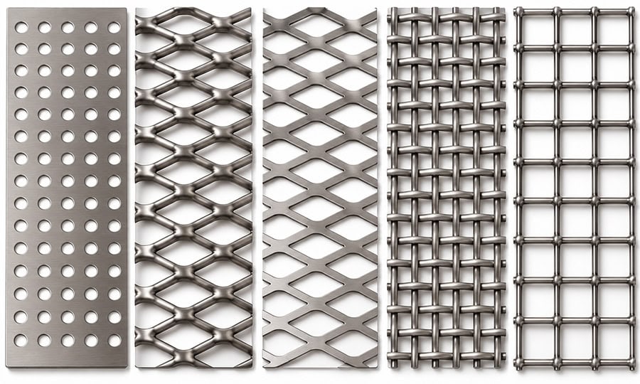
| Selection question | Engineering decision |
| Perforated metal vs expanded metal | Choose perforated metal panels when the design needs a defined hole field and solid mounting lands. Expanded metal mesh needs strand orientation and cut-edge retention specified. |
| Expanded metal vs wire mesh | Expanded metal has integral strands and bonds; wire mesh panels use interlaced wires or welded intersections. Compare actual openings, section dimensions and attachment before choosing. |
| Flattened vs raised expanded metal | Choose a flattened profile where contact geometry requires it; check finished dimensions. Raised material retains its formed profile and needs clearance for its overall thickness. |
| Woven vs welded wire mesh | Woven cloth needs control of wire movement and cut edges. Welded mesh panels require sound intersections and suitable attachment to the supporting frame. |
| Perforated sheet vs wire mesh | A folded perforated sheet can retain solid mounting and bend zones. A wire grid needs an attachment arrangement that captures its edges and transfers the required load. |
1.1 Perforated Sheet Metal
Perforated sheet metal starts with a continuous sheet containing a repeated hole pattern. It can retain unperforated material around fasteners, folds and panel edges. These solid zones provide tool contact and mounting surfaces that a fully open metal mesh cannot offer in the same form.
Base sheet metal material selection on the service environment and forming requirements. Perforated aluminum sheet needs its alloy and temper specified. A perforated steel sheet specification must identify its grade and coating; perforated stainless steel sheet also needs a defined grade and finish.
On a perforated metal sheet drawing, locate the hole field and solid borders relative to the finished outline. Perforated metal patterns leave different ligaments between holes, affecting forming and local stiffness. A stock perforated plate specification does not establish finished-panel flatness or mounting accuracy.
1.2 Raised and Flattened Expanded Metal
Expanded metal sheet is slit and stretched to create connected strands and openings. Raised expanded metal retains the formed profile; flattened expanded metal undergoes rolling to reduce that profile. Expanded steel mesh and expanded aluminum mesh therefore require more than an alloy and nominal thickness on the purchase specification.
For expanded metal dimensions, distinguish long-way and short-way dimensions from the clear openings. SWD and LWD describe mesh geometry; SWO and LWO describe opening dimensions. Confirm the supplier’s dimension convention, then state strand width, strand thickness, orientation and finished panel size.
Use finished-product dimensions when ordering expanded metal sizes. Define the cut boundaries of expanded metal panels: exposed strand ends need edge treatment or capture before handling and assembly.
1.3 Woven and Welded Wire Mesh
Woven wire mesh, also called woven wire cloth, uses interlaced wires; capture its cut edges where movement or unravelling would affect fit or function. Welded wire mesh joins wires at intersections, but wire size, weld condition and frame attachment still determine the finished assembly’s behavior.
Specify the grade, aperture and wire diameter of stainless steel wire mesh. When buying metal mesh sheets for cutting, also state the required edge condition. Finished metal mesh panels need panel dimensions and mounting interfaces in addition to the stock specification.
Safety mesh panels still require an application-specific guard assessment. The product name does not establish safe openings, adequate stiffness or secure installation.
2. Specify Openings and Open Area
Specify dimensions that can be inspected. Wire mesh sizes based only on mesh count leave wire thickness and clear opening unresolved. For perforated metal open area or mesh open area, identify whether the percentage describes the patterned field or the whole panel.
2.1 Aperture Wire Diameter and Pitch
For square woven mesh, define the clear opening and wire size separately:
| Dimension | Definition |
| Wire mesh aperture, w | Clear opening between adjacent wires, in mm |
| Wire mesh wire diameter, d | Wire diameter, in mm |
| Pitch, p | Center spacing between adjacent wires; p = w + d |
ISO 4783-1:1989, Clause 4, gives the geometric open area:
Ao (%) = 100 × [w / (w + d)]²
ISO 9044:2016 addresses square-aperture industrial woven cloth for screening. Its aperture inspection requirements can inform an agreed specification, but the standard has limited application outside screening and excludes pre-crimped screens, welded screens and cloth coated after weaving. Add the finished-panel requirements separately.
2.2 Perforated Fields and Solid Borders
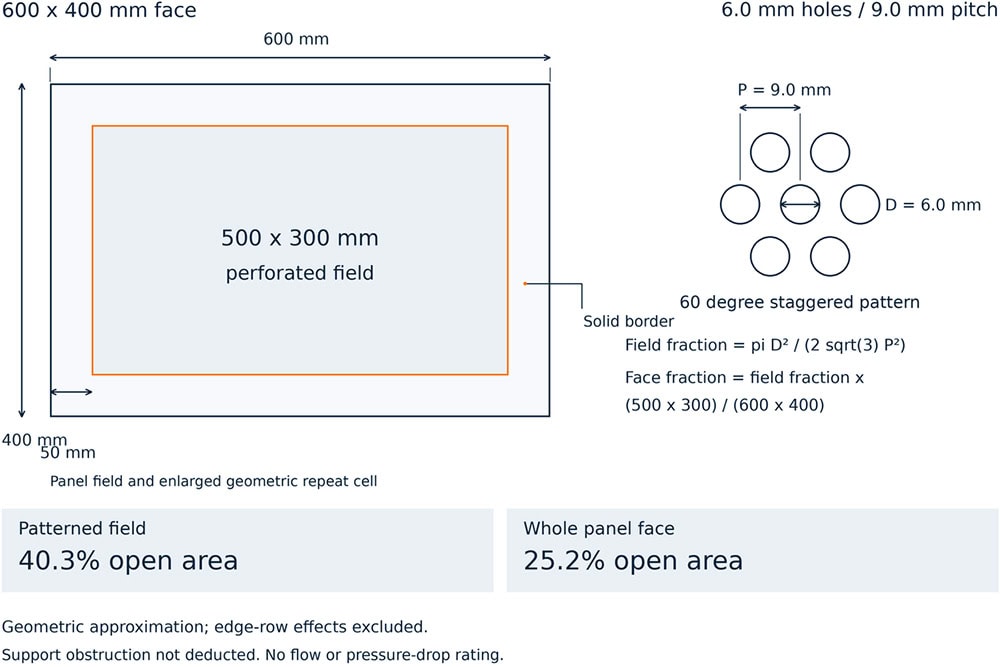
Specify perforated metal hole sizes, pitch, pattern orientation and margins. Check ligament width as well as the opening. ISO 10630:1994 covers industrial plate-screen specifications and tests, principally low-carbon steel within its scope. Its stock flatness provisions do not automatically apply to a formed panel with solid zones. Perforated sheet open area must identify whether the denominator is the patterned field or the full panel face.
For a regular 60° staggered round-hole field, the geometric area fraction is πD²/(2√3P²), where D is hole diameter and P is pitch. The case in Section 6 uses D = 6.0 mm and P = 9.0 mm: approximately 40.3% within the field. A 500 × 300 mm field within a 600 × 400 mm face gives approximately 25.2% over that face, before deducting support obstruction and edge-row effects. Neither percentage is a flow rating.
3. Design Enclosure Ventilation
Design enclosure ventilation around the required cooling flow and available pressure. Metal ventilation panels, perforated ventilation panels and ventilation grilles all become part of that airflow path. Include filters, internal components, outlet restrictions and the fan operating point.
An industrial enclosure or equipment cover needs a complete inlet-to-outlet path. Increasing inlet area cannot remove a restriction elsewhere in that path.
3.1 Separate Free Area from Pressure Drop
Grille free area and ventilation free area describe unobstructed geometry; pressure drop describes resistance at a stated flow condition. Perforated plate pressure drop depends on hole geometry, thickness, velocity and installation. Wire mesh pressure drop also depends on wire diameter, weave and orientation. Open area alone cannot predict mesh airflow.
When comparing perforated metal airflow data, require the flow rate, exposed area and test configuration. Perforated sheet pressure drop data from a different thickness or hole pattern may not represent your panel. Include frames and crossbars in the installed assessment.
Select vent mesh openings against the debris to exclude. Ventilation mesh needs cleaning access, and air vent mesh near a fan must be assessed with its mounting support. Dust on industrial metal vent covers can restrict cooling despite adequate initial free area.
4. Design Machine Guard Panels as a System
Machine guarding design starts with the hazard and access routes. Machine guards and equipment guards must remain effective after mounting, loading and maintenance. A material sold as machine guard mesh does not establish the performance of the installed assembly.
4.1 Assess Openings and Hazard Distance
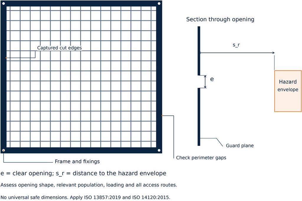
Select machine guarding mesh size together with the distance to the hazard. ISO 13857:2019, Clause 4.2.4, addresses reaching through openings; the applicable assessment depends on opening geometry and the relevant population. Check reaching over, under and around the barrier as well.
Machine guarding safety distance is not a single clearance applicable to every aperture. Specify the maximum permitted opening, accounting for manufacturing variation and deformation. For wire mesh machine guards, inspect perimeter gaps and joints as well as the nominal mesh. Mesh guarding that meets a stock aperture specification can still leave an access route at its frame.
4.2 Check Frames Fixings and Impact Requirements
An effective wire mesh frame or expanded metal frame captures the cut edges and supports the panel over its unsupported span. Assess loads, deflection, fixing retention and possible ejected material as part of machine guard design.
ISO 14120:2015 addresses guard construction, including containment in Clause 5.1.3, impact resistance in Clause 5.4.2 and rigidity in Clause 5.4.3. Machine guarding standards do not provide one universal sheet thickness or impact rating for every application. Define the hazards, load conditions and required verification; select a fixed guard or movable guard to suit access needs. Interlocking devices are outside ISO 14120’s scope.
Record the hazard setback, perimeter gaps and fixing requirements on the assembly drawing. Use tolerances and drawing standards to define the mounting datums and dimensions that preserve those clearances.
5. Plan Cutting Bending Joining and Finishing
Agree on the manufacturing sequence before releasing the drawing. Cutting expanded metal can leave projecting strands; cutting wire mesh can release individual wires. Define edge capture or edge preparation before deciding how the panel will be handled and assembled.
5.1 Keep Mounting and Bend Zones Functional
For bending perforated sheet metal, reserve a bend zone and mounting land that suit the material, hole pattern and tooling. Holes near a bend can distort, and interrupted tool contact can affect the fold. Apply sheet metal design guidelines to the solid zones, then review the adjacent perforations with the fabricator.
Bending expanded metal also requires control of strand direction, tooling contact and opening deformation. Perforated metal fabrication should specify the forming sequence, support and finished inspection state; a universal hole-to-bend ratio cannot replace that review.
5.2 Control Cut Edges Distortion and Coatings
When welding wire mesh to a frame, control heat input, attachment spacing and restraint to limit weld distortion. For custom wire mesh panels, choose connections that retain wires and transfer the required loads without unacceptable gaps.
Specify burr removal before coating. Powder coating does not remove sharp metal edges. Plan sheet metal surface finishing around coating coverage, cut-edge protection and dimensions that must remain functional. Inspect panel flatness after the operations that can change it, including forming and joining.
6. Prepare the Drawing RFQ and Inspection Plan
For custom perforated metal panels and custom wire mesh panels, provide the finished assembly requirements alongside the stock specification. Define sheet metal tolerance control around mounting datums and the inspection setup.
| RFQ or drawing field | Information to include |
| Function and environment | Ventilation, fan guard, access panel or machine enclosure; debris, corrosion and cleaning conditions |
| Material and geometry | Grade, condition, thickness or wire size, aperture, pitch, pattern and orientation |
| Finished structure | Panel size, solid borders, folds, frame, support positions and mounting interfaces |
| Manufacturing and finish | Cut edges, burr limits, joining, coating and protected contact surfaces |
| Functional requirements | Cooling conditions; for guards, hazard distance, maximum aperture and load requirements |
| Inspection | Datums, free or mounted condition, support, tightening, measurement locations and acceptance limits |
| Supply | Quantity, drawing revision and agreed inspection sampling |
EPOC CRAFTER shop-floor data: improving a ventilation panel assembly. A dry indoor packaging-machine control cabinet used a 1.5 mm DX51D+Z panel, Z275 coating, supply condition M. Its envelope was 600 × 400 × 22 mm, with a 500 × 300 mm perforated field, 50 mm solid borders, 6.0 mm holes and 9.0 mm staggered pitch. Four 22 mm flanges were bent to 90° with a 1.5 mm internal radius. The panel provided ventilation and coarse debris exclusion, without a personnel-protection function.
Material and hole geometry stayed unchanged. The revised process used alternating opposite-side forming in segments with a full-area support plate. A central crossbar reduced the maximum clear span from 500 to 250 mm, and six distributed M6 fixings secured the panel. These changes were evaluated together, so the results do not isolate one change’s contribution.
| Inspection result | Before | After |
| Panels inspected | 30 | 30 |
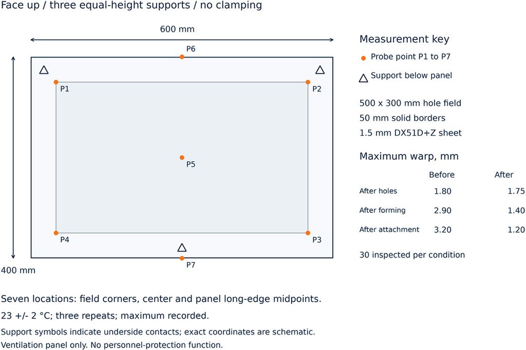
| Maximum warp after perforation | 1.80 mm | 1.75 mm |
| Maximum warp after forming | 2.90 mm | 1.40 mm |
| Maximum warp after attachment | 3.20 mm | 1.20 mm |
| Maximum mounting-hole position deviation | 1.10 mm | 0.45 mm |
| Maximum panel-to-frame gap | 1.60 mm | 0.55 mm |
| Maximum clear aperture | 6.18 mm | 6.17 mm |
| Maximum burr height | 0.18 mm | 0.09 mm |
| Sample assemblies meeting combined criteria | 22/30 | 29/30 |
| Panels requiring fitting or rework, per 100 produced | 8 | 1 |
| Assembly time | 12.6 min/panel | 8.4 min/panel |
Each 100-panel batch contributed 30 inspected panels. Warp measurements used seven locations, the face upward on three equal-height supports at the solid perimeter, without clamping. Measurements were repeated three times and the maximum recorded at 23 ± 2 °C. Assembly checks used a supported frame and alternating tightening to 5.0 N·m.
Combined acceptance required position deviation ≤0.80 mm, assembly gap ≤0.80 mm, clear aperture ≤6.30 mm, burr height ≤0.15 mm and forming warp ≤2.00 mm. The table reports maxima across the samples; the 22/30 and 29/30 counts reflect joint compliance on individual assemblies. Local gaps remained near the crossbar ends. The case supports controlling forming and support together for this ventilation panel; it establishes neither a pressure-drop rating nor machine-guard compliance.
7. Frequently Asked Questions
7.1 Which material should I choose for machine guard panels?
Choose by hazard, required visibility, environment, loading and attachment. Solid mounting zones can favor perforated sheet; expanded metal and wire mesh require suitable edge retention. No format establishes guarding safety by itself.
7.2 Does a higher open area always mean better airflow?
No. Open area describes geometry. Compare pressure drop at the required flow with the actual panel thickness, openings, supports and surrounding components. A smaller opening may exclude debris but also change resistance and cleaning needs.
7.3 Can perforated sheet metal be bent?
Yes, with a suitable material, pattern, bend zone and tooling arrangement. Specify allowable hole distortion and finished flatness. The case above improved forming and assembly results without changing the perforated field.
To request a panel quote for custom perforated metal panels or custom wire mesh panels, send the completed RFQ fields above. For machine guard panels, include the hazard-distance and guard-performance requirements.
Ready to Quote Your CNC Prototype?
Upload your STEP file and get a DFM review + quote within 12 hours.
No tooling cost. Minimum 1 part.