

Dewey Wu General Manager & senior mechanical engineer at EPOC CRAFTER, 15 years in design engineering, quality, and metallurgy. Hands-on across CNC machining, metalwork, sheet metal, and prototyping (subtractive + 3D printing).
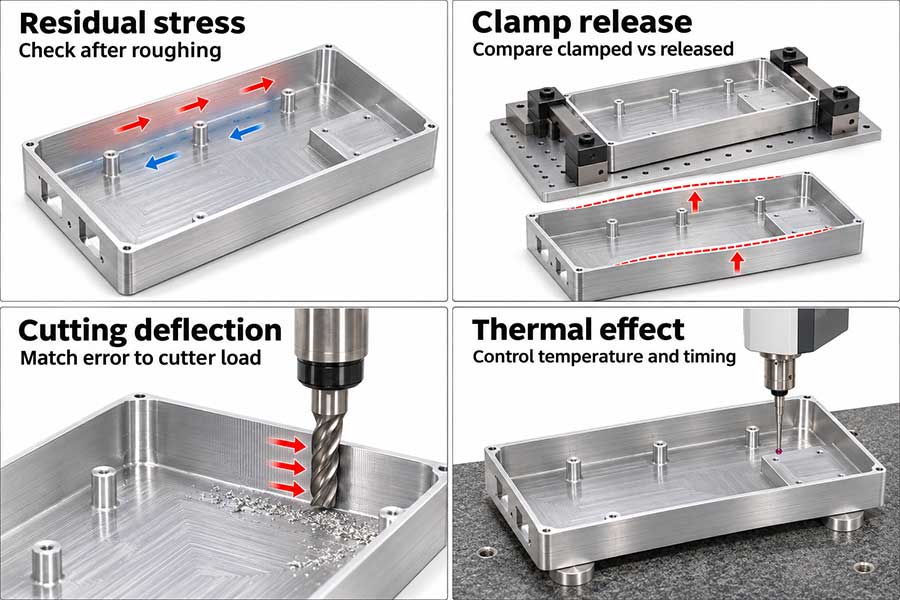
Thin-walled aluminum parts can warp after CNC machining when material removal changes the stress balance, cutting forces bend unsupported walls, or a fixture holds the walls straight until the clamps are released. Temperature and inspection conditions can also affect the readings.
To narrow down the cause, measure the same features while clamped, immediately after unclamping, and after a controlled holding period. Use consistent datums, supports, and measurement methods. Compare when the wall moves and in which direction before changing the machining process.
1. Confirm When the Part Distorts
A fixture may hold a thin wall straight even though the released part is out of tolerance.
Measure both conditions before changing feeds or material. Use repeatable references and record when the wall moves.
1.1. A Real Production Case: Aluminum Housing Walls Moved After Unclamping
In a real EPOC CRAFTER production and finished-part inspection case, both long walls of a 6061-T651 aluminum controller housing bowed outward after CNC machining.
The housing was designed to support an electronic control board and a sealed cover. Its main dimensions were:
| Feature | Actual case specification |
| Material | Aluminum 6061-T651 rolled plate |
| Finished dimensions | 240.0 × 160.0 × 28.0 mm |
| Perimeter wall thickness | 2.0 mm |
| Wall height | 24.0 mm |
| Unsupported long-wall span | Approximately 220 mm |
| Base thickness | 4.0 mm |
| Upper-edge profile deviation limit | ≤ 0.12 mm |
The 24 mm wall height and 2 mm wall thickness gave a ratio of 12:1. With roughly 220 mm of unsupported length, the long sides were susceptible to both cutter loads and fixture restraint. Bending stiffness depends strongly on thickness, as well as wall geometry and support conditions.
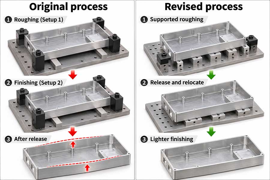
The original fixture clamped the four corners while two parallel blocks supported the base. The center remained unsupported. Roughing and final wall milling were carried out in two setups.
The final wall-milling pass left light, periodic tool marks. No pronounced squealing or tool chipping was observed.
Most of the visible movement appeared when the four clamps were released.
1.2. What the Clamped, Unclamped, and 24-Hour Measurements Showed
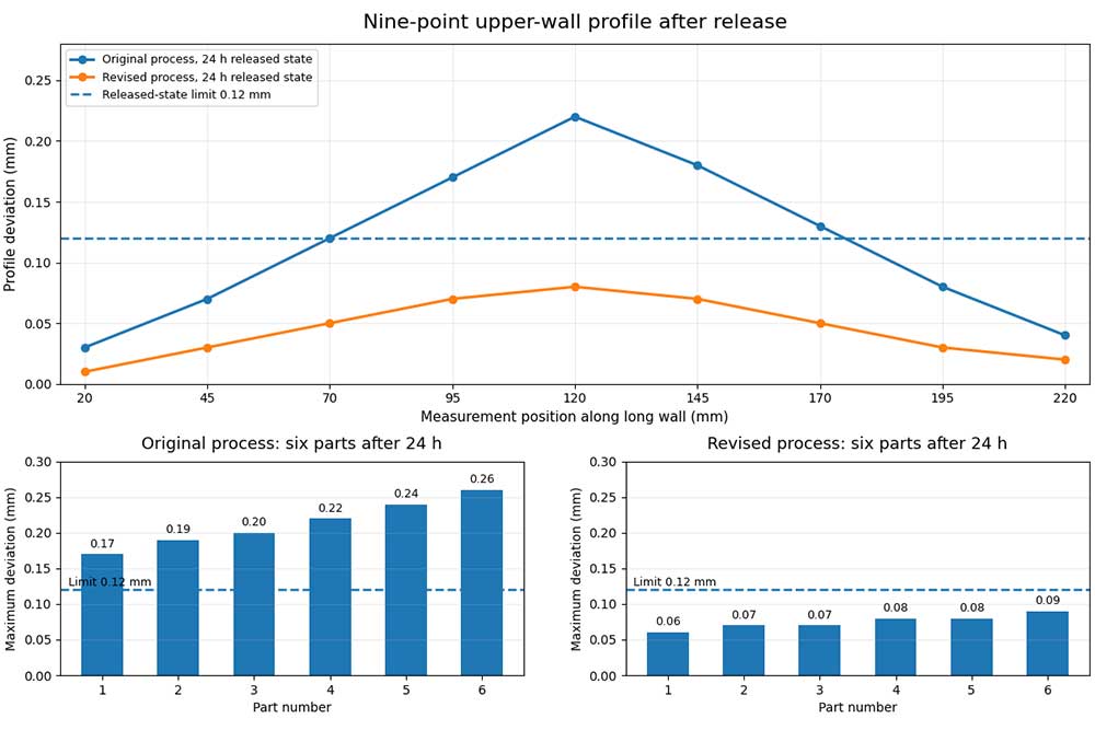
A coordinate measuring machine (CMM) measured nine equally spaced points along the upper edge of one long wall. The points ran from 20 to 220 mm along the wall, at 25 mm intervals.
Measurements used the specified base and locating sides. The inspection area was at 22.0°C, and the part was held there for 30 minutes before measurement.
| Inspection condition | Maximum absolute profile deviation | Result against 0.12 mm limit |
| Original clamped condition | 0.04 mm | Below numeric limit; clamped only |
| Immediately after unclamping | 0.21 mm | Exceeds limit |
| After 24 hours unclamped | 0.22 mm | Exceeds limit |
The maximum recorded deviation rose from 0.04 to 0.21 mm on unclamping, an increase of 0.17 mm. After 24 hours it reached 0.22 mm. Most of the observed change was immediate, so adjusting the finishing feed alone would leave the main problem unresolved.
Across the six parts manufactured using the original process, the recorded maximum deviations after 24 hours were 0.17, 0.19, 0.20, 0.22, 0.24, and 0.26 mm.
None of the six parts met the 0.12 mm profile deviation limit.
These readings make fixture restraint a priority in the investigation. They do not show that clamping force was the only cause. Removing stock from the rolled plate also changed its stress balance.
1.3. Do Not Diagnose the Cause From a Single Measurement
A dimension measured while the fixture restrains the wall does not establish the geometry of the released part.
Record movement at three different stages:
- Movement during machining: investigate cutting force, changing wall stiffness, tool engagement, and workpiece support.
- Movement immediately after unclamping: examine elastic recovery from fixture restraint and changes in the stress balance after material removal.
- Movement during a subsequent hold: check for further geometric changes under documented temperature, support, and measurement conditions.
The 0.17 mm change on release points first to fixture restraint and stress redistribution. A spindle-speed change would not explain that response.
2. Distinguish the Mechanisms Behind the Movement
Several mechanisms may act on the same wall. Keep the measurement references fixed, record when the movement occurs, and check whether each suspected cause matches its direction and magnitude.
2.1. Residual Stress Released by Material Removal
6061-T651 plate is stretch-stress-relieved but can still retain internal stress. Milling a large cavity removes material that previously balanced stresses through the plate. Asymmetric removal can leave the remaining walls distorted. Stock condition also matters: the 6061-T6 versus T651 temper comparison explains how the two tempers differ.
Measure the free-state profile after roughing, before the final finishing passes. A shift at that stage supports a contribution from material removal, although it cannot reveal the plate’s original stress distribution.
2.2. Elastic Recovery When the Fixture Opens
CNC workholding may hold a flexible wall close to its nominal position. When clamping force is removed, elastic deformation recovers and the wall springs outward. The original fixture used corner clamps and supported the base along just two strips. The rise from 0.04 to 0.21 mm makes that restraint one of the first conditions to test.
Elastic deformation can recover when clamps open. A finding of plastic deformation would require evidence of permanent strain; these measurements alone cannot establish that.
Before recutting the part, repeat a controlled clamp-and-release cycle. Movement that repeats at the same locations points toward fixture restraint. A separate EPOC CRAFTER case on thin wall gauge distortion shows how constraints during measurement can affect an inspection result.
2.3. Cutting Deflection and Machining Chatter
Wall thickness, unsupported span, and the material left after each pass affect bending stiffness. During finish machining, radial cutting force can push the wall away from the cutter, leaving taper or an error that varies with wall height. Machining chatter may leave periodic marks, but those marks do not establish the cause of movement after release.
High speed machining will not fix a wall that springs outward when unclamped. Check cutter engagement and support as stiffness changes, then measure the released wall before adjusting speed.
Measure the wall profile along its height and length. Compare the readings with cutter direction, tool engagement, and support points. This case showed light periodic marks without pronounced squealing or tool chipping. Chatter alone would not explain the large change upon unclamping.
2.4. Thermal Deformation and Measurement Conditions
Thermal deformation can change a part’s dimensions as it cools. Record the part temperature, time since machining, and support condition before diagnosing poor dimensional stability. This case was inspected at 22.0°C after 30 minutes in the inspection area. No controlled temperature sweep was reported.
| Possible mechanism | Most useful observation | What the observation cannot prove alone |
| Residual stress redistribution | Free-state shape changes after stock removal, before final finishing | The original internal stress field |
| Fixture restraint and release | Large change immediately upon unclamping | That clamp pressure was the only cause |
| Cutting deflection or vibration | Taper, load-sensitive shape or repeated cutter marks | That post-release movement is entirely cutting-force driven |
| Thermal or inspection state | Measured shape changes with temperature or elapsed time | Permanent material deformation |
3. Change the Process That Causes the Error
The revised route changed both the fixture support and the order of stock removal. It did not rely on a fixed spindle speed, clamping pressure, or minimum wall-thickness rule.
| Process element | Original route | Revised route |
| Support and clamp contact | Two support strips; four corner clamps | Three-point primary support with non-overconstraining auxiliary pads; clamps on thick mounting bosses |
| Cavity restraint | No removable internal wall support specified | Removable close-fitting support inside cavity |
| Stock removal sequence | Rough and semi-finish, then continuous long-wall finish | Symmetric layered cuts, alternating sides; unclamp and re-locate after roughing |
| Finish stock / cutting | 0.25 mm per side after semi-finishing | 0.20 mm per side; light climb-milling passes and small radial engagement |
The revised fixture moved clamp contact away from the upper walls and supported the base without forcing it flat. After roughing, the part was released and relocated before the lighter finishing passes. The low force CNC machining guide discusses cutter loading and fixture choices for thin sections.
High efficiency milling can shorten roughing time while the stock is still rigid and well supported. The finishing passes need lighter engagement and a released-state check. A high material removal rate has little value if the walls move out of tolerance after unclamping.
The revised route used the same 6061-T651 rolled plate. The aluminum CNC material selection decision should still account for geometry, stock form, and service conditions. Changing temper alone would not demonstrate a fix for this release movement.
Adaptive machining can help control tool engagement during supported roughing. A shorter cycle, however, says nothing about the final shape of an unsupported wall. Inspect the released part before treating a faster process as an improvement.
4. What Changed Across the 12 Production Parts
Both groups contained six parts with the same housing geometry. After the fixture and cutting sequence were revised, the first part’s maximum deviation was 0.03 mm while clamped, 0.07 mm immediately after release, and 0.08 mm after 24 hours.
| Recorded result | Original process, six parts | Revised process, six parts |
| 24-hour released-state maximum deviations (mm) | 0.17, 0.19, 0.20, 0.22, 0.24, 0.26 | 0.06, 0.07, 0.07, 0.08, 0.08, 0.09 |
| Parts within 0.12 mm limit | 0 of 6 | 6 of 6 |
| Machining time per part | 48 min | 54 min |
| Inspection time per part | 12 min | 15 min |
| Parts requiring rework assessment for this characteristic | 6 | 0 |
The revised process took 54 minutes to machine and 15 minutes to inspect each part, compared with 48 and 12 minutes for the original route. Across six parts per group, those operations totaled 414 minutes for the revised route and 360 for the original, an increase of 54 minutes. All six revised parts met the edge requirement; the six original parts required rework assessment. Without rework costs, these figures do not support a claim of dollar savings.
Fixture contact, support, and cutting sequence all changed together. The results verify the revised route as a whole; they cannot show how much improvement came from each change.
5. Inspect in the Condition That Governs Acceptance
Nine points along the upper edge were checked against the 0.12 mm maximum absolute profile deviation limit. This sampled edge check is neither a complete surface profile tolerance evaluation nor a flatness measurement of the housing base.
For released-state acceptance, use the same datums and nine locations with the part on low-restraint supports. Record the unclamping time, conditioning period, and inspection temperature. CMM inspection provided the coordinates, with a dial indicator used to check movement at the wall center.
The CMM coordinate resolution was 0.001 mm, and the dial indicator had 0.01 mm divisions. Neither figure establishes measurement uncertainty. Geometric tolerancing must identify the controlled feature and its datum relationship; the inspection method must define how the requirement is evaluated. A near-limit result cannot be accepted on display resolution alone.
A flatness tolerance controls a surface without datums. A surface profile tolerance can reference a datum system. Neither substitutes for the nine-point upper-edge limit used in this case. CMM dimensional inspection should record point locations, alignment, the released condition, and the associated drawing requirement.
6. Put the Right Information on the RFQ
An aluminum CNC milling RFQ for this housing should specify 6061-T651 rolled plate, the 2.0 mm walls, their 24.0 mm height, the approximately 220 mm unsupported span, mating interfaces, and the 0.12 mm released-state limit. Include the 24-hour hold and inspection datums. A drawing note that states only ‘±0.12 mm’ leaves the controlled feature and inspection condition unclear.
This housing locates an electronic control board and a sealed cover, so the upper-wall shape affects their fit. Such interfaces also matter in consumer electronics CNC housings. Compare CNC machining supplier capabilities based on the supplier’s proposed support and inspection method, not machining capacity alone. Include released-state verification in the rapid prototyping inspection requirements so suppliers quote the same acceptance work.
First article inspection should include the upper-edge profile in the released condition when that governs acceptance. Ask for the nine-point measurements and datum references in the FAI inspection report, along with the other required dimensions. Without those details, the quoted fixture, inspection time, and rework exposure are hard to compare.
The revised process added nine minutes per part and met the limit on all six revised parts. Compare quotes using both operating time and the agreed acceptance method. These data do not establish a dollar saving or a production-wide yield rate.
7. What Simulation and Probing Can Establish
Process simulation can estimate how fixture restraints, wall stiffness, and material removal affect deflection. Published research on adaptive clamping of thin-walled 6061-T6 parts combined finite-element models with CNC and CMM measurements. Those models need calibrated loads and support conditions; they cannot certify the released geometry of this housing.
On-machine probing can detect a setup shift while the part is still restrained. It cannot replace an inspection after unclamping. Use probing to control the process and off-machine measurements to judge acceptance when the released geometry changes.
8. Frequently Asked Questions
8.1. Can 6061-T651 Still Warp After Machining?
Yes. Even stretch-stress-relieved plate can move after major stock removal or release from a fixture. The housing used 6061-T651, and all six parts made by the original route exceeded the released-state limit.
8.2. Will More Spring Passes Fix a Warped Thin Wall?
An extra finish pass helps only when cutting deflection caused the error and the wall remains adequately supported. Repeating the pass while the fixture forces the wall straight will not correct distortion that appears on release.
8.3. Which Condition Should a Supplier Use to Accept a Thin-Wall Part?
Use the condition defined by the drawing requirement and agreed inspection plan. In this case, the reported comparison used the released condition after 24 hours. A reading taken only under machine clamping would have missed the out-of-tolerance geometry.
Ready to Quote Your CNC Prototype?
Upload your STEP file and get a DFM review + quote within 12 hours.
No tooling cost. Minimum 1 part.