

Dewey Wu General Manager & senior mechanical engineer at EPOC CRAFTER, 15 years in design engineering, quality, and metallurgy. Hands-on across CNC machining, metalwork, sheet metal, and prototyping (subtractive + 3D printing).
Do not release a CNC prototype for machining until you know how its critical features will be made, held, measured, and accepted. A CAD model cannot show whether a pocket floor will spring back after unclamping or whether a hole pattern can be inspected from the specified datums. Design verification needs a defined process route and an inspection plan for the finished part. Approve the job when those conditions are settled, revise the route when it is not adequate, and hold the release when a critical requirement remains undefined.
1. Identify the Features That Must Work
In CNC machining design, start with the surfaces that locate the part in its assembly, followed by the holes and interfaces that determine fit or motion. These are critical to quality features. Tighten tolerances where a deviation would affect function, not simply because the machine can hold a smaller number. Design for manufacturability means matching those features to a practical cutting, clamping, and measurement plan before the RFQ goes out.
1.1. Separate Size From Geometric Accuracy
A hole can meet its diameter limit yet fail positional tolerance. A pocket floor can meet its thickness requirement yet fail flatness. Size, form, location, orientation, and surface texture describe different characteristics and need separate controls where function requires them. Specify drawing datums for geometric controls that depend on a reference. Flatness controls a surface’s form without a datum. Functional prototyping may also require assembly or load tests, with acceptance criteria separate from dimensional inspection.
The existing manufacturing DFM design guidelines explain general geometric choices. This guide asks a more specific question: can the proposed operations make and verify the features the prototype needs? Design for machining becomes useful when it resolves that question for this part.
1.2. A Real Shop-Floor Failure: Thickness Passed, Flatness Failed
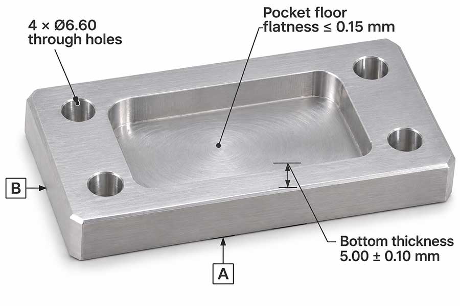
In EPOC CRAFTER’s real production case C03, a 20-piece batch of 6061-T6 aluminum sensor mounting brackets was made for automated inspection equipment. Each part measured 100.00 × 60.00 × 12.00 mm. A 70.00 × 35.00 mm pocket, 7.00 mm deep, left a 5.00 mm floor. Four Ø6.60 mm clearance holes formed the mounting interface. The bracket located a sensor under low loads; the case does not establish structural safety performance.
| Critical characteristic | Requirement | Initial result | Disposition |
| Floor thickness | 5.00 ± 0.10 mm | 4.91 mm | Pass |
| Pocket floor flatness | ≤ 0.15 mm | 0.23 mm | Fail: 0.08 mm over limit |
The initial floor thickness met its limit, but flatness did not. During the process review, the team identified clamping restraint and material removal as risks to the pocket floor. It kept the CAD geometry, changed the cutting and clamping sequence, and checked the floor after unclamping. The revised flatness measurement was 0.08 mm. No change to the specified flatness limit was needed.
1.3. Write the Acceptance Condition Into the Plan
Define the inspection state for each critical feature. A thin floor may need measurement after unclamping. A hole pattern machined across setups needs agreed datums and a repeatable inspection alignment. The machine work offset is not the drawing datum reference frame. Before release, an engineering design review should confirm that the drawing revision, machining route, instrument, and acceptance condition refer to the same requirements.
2. Convert CNC Design Risks Into Verifiable Actions
Use the table to record what can fail, what the supplier proposes to change, and what evidence would support acceptance. A DFM review should name the affected feature and a feasible way to machine and inspect it. Request DFM feedback on any proposed exception and the functional requirement it might affect. These are project-specific decisions, not ISO risk scores or universal minimum wall-thickness rules.
| Risk at design release | What can go wrong | Evidence required | Release action |
| Thin pocket floor or wall | Deflection while held; form changes after release | Support and clamp sequence; measurement in required state | Revise process or Hold critical flatness |
| Hole pattern across setups | Datum transfer or locating error | Coordinate setup and datum alignment plan; positional inspection | Confirm references before cutting |
| Deep pocket and small internal radius | Long tool or smaller finishing cutter; access and cycle penalties | Cutter and holder clearance; credible process path | Revise nonfunctional radius or accept justified route |
| Fit-critical bore | Diameter passes but roundness, axis or assembled fit fails | Fit conditions; bore geometry and inspection | Confirm application-specific criteria |
| Ambiguous finish or inspection | Two suppliers price or check different scope | Controlled surface callouts and measurement methods | Hold RFQ until requirements agree |
2.1. Thin Sections: Check the Part After It Is Released
Clamping force can bend a thin floor. Cutting loads may make it move during milling, while material removal can change the residual-stress balance. The visible distortion does not, by itself, tell you which mechanism dominated. Record the support points, clamping sequence, finishing stock, and measurement state. An in-machine measurement taken while the part is restrained cannot, by itself, prove flatness after release.
2.2. Hole Location: Control the Datum Transfer
Hole diameter alone cannot confirm that a mounting pattern will assemble. When the part is flipped or moved to another fixture, check the locating surfaces, CNC work offsets, and inspection datums separately. Fixture design must locate the workpiece repeatably without hiding distortion under clamp load. Probing may reduce setup time; it cannot correct poor datum selection or an unstable setup. Judge positional accuracy against the drawing’s datum reference frame.
2.3. Deep Pockets: Verify Tool Access Before Predicting Cost
Pocket depth alone does not tell you how difficult the feature will be to mill. A narrow opening, small internal radius, or obstructed holder approach may require a thinner cutter and extra finishing passes. Check usable cutter diameter, reach, chip evacuation, and floor-finish requirements before quoting the operation. Increasing an internal radius is a valid cost-saving change only when it does not alter a functional corner or interface.
The existing complex CNC RFQ cost drivers article explains the time and cost effects of these features. Here, the decision is whether the proposed prototype route is manufacturable and inspectable.
2.4. Bearing and Locating Bores: Fit Depends on the Assembly
An H7 callout alone does not define a suitable bearing housing. Select the fit from the bearing type, load direction, ring rotation, housing material, operating temperature, and assembly conditions. Bore diameter does not replace roundness, cylindricity, alignment, or surface-texture requirements where those affect function. Engineering must approve the fit for the actual assembly, not a generic bearing-seat rule.
The ISO hole shaft fit calculator can show dimensional limits, but it cannot predict bearing behavior once the assembly is loaded.
3. Verify the Machining Route, Not Just the CAD Model
3.1. Stock and Setup Plan
Record the alloy and temper, stock form, locating surfaces, clamping contact, roughing order, finishing allowance, and subsequent setups. A workable design for CNC machining accounts for the stock and equipment actually being used. Plate and extrusion can produce the same final geometry but require different clamping and stock-removal sequences. A generic tool-reach ratio or minimum wall thickness cannot approve this part without the cutter, holder, fixture, and tolerance requirements.
At each setup change, identify which locating features remain available and how the next operation will recover the required coordinates. Confirm that both cutter and holder can reach the features without hitting the fixture. Do not release a route that relies on a reference that cannot be reconstructed for inspection or that finishes a flexible surface before major stock removal is complete.
3.2. Select Go, Revise, or Hold
| Status | Decision criterion | What happens next |
| Go | Critical features have feasible operations, controlled requirements and an agreed acceptance method | Release revision for approved first-article manufacturing |
| Revise | A design or process change can remove a defined risk without changing intended function | Update controlled route or geometry; rerun affected checks |
| Hold | A critical specification, setup capability, inspection state or supplier exception remains unresolved | Resolve the issue before production authorization |
Go means the agreed first-article checks may proceed under the inspection plan. It does not guarantee a defect-free batch. Design validation answers a separate question: will the assembled prototype perform under its intended load and environment? Dimensional inspection does not establish fatigue life, vibration resistance, or long-term performance unless those tests are separately specified.
3.3. Choose the Verification Gate That Matches the Risk
Measure a pocket floor after releasing it when free-state form is the acceptance requirement. For a hole pattern crossing setups, first confirm the datums can be established consistently. The manufacturing engineer should place checks after the operations most likely to disturb each critical feature, while a process correction is still possible. First article inspection verifies the initial product against its specified characteristics; it does not guarantee that every later part will conform.
Reject a setup plan with no workable inspection state. Adequate machine travel does not guarantee gauge or CMM probe access to a recessed surface. Check the probe approach and part orientation before approving the plan. Where access is blocked, change the inspection setup or a nonfunctional feature. Having a CMM on site is not a substitute for a defined measurement method.
4. Define Inspection Before Approving the Prototype
4.1. Inspect Each Control With the Right Method
An engineering drawing must identify the characteristics that govern acceptance. A micrometer can check accessible thickness; a bore gauge measures hole size. CMM inspection can evaluate position or form when the point coverage and datum alignment are suitable. A stylus instrument measures surface texture under its specified settings. For digital inspection, retain the drawing revision, method, results, and decision rule together. A Ra measurement does not establish flatness.
Use geometric dimensioning and tolerancing to describe the relationships that matter to assembly. ISO 1101:2017 defines GPS geometrical tolerancing symbols and rules, but the complete datum interpretation also depends on the applicable datum standard and drawing requirements. Apply the agreed acceptance decision rule when evaluating measurements, including uncertainty where relevant; one guard band is not appropriate for every characteristic.
The CNC tolerance standards reference explains common tolerance systems; it cannot replace approval of the limits and measurement methods for the actual features.
4.2. A Drawing Revision Must Match the Quoted Inspection Scope
Two suppliers cannot produce comparable quotes from different engineering instructions. Send one controlled model and drawing revision, specified material and temper, order quantity, required finishes, critical datums and tolerances, inspection records, and delivery constraints. Identify which characteristics need full first-article reporting and which can be covered by agreed routine checks.
Tolerance analysis can show which dimensions dominate an assembly clearance. A simple one-dimensional stack-up does not account for form, position, or thermal effects that are absent from the model. Before relying on the calculated gap, check that its assumptions match the drawing’s functional geometric requirements.
The assembly tolerance stack up calculator supports a preliminary dimension-chain check but cannot account for geometric effects outside its model.
5. Align the RFQ With the Actual Engineering Decision
For CNC prototyping, compare quotes only after the suppliers have priced the same work. Check material assumptions, technical exceptions, fixture and tool-access limits, finishing, inspection exclusions, and first-article reporting. A cheaper quote that excludes a required measurement is not an equivalent offer.
| RFQ item | What the supplier must confirm | Decision consequence |
| CAD and drawing | Same controlled part revision and units | No hidden geometry change |
| Material | 6061-T6 or specified grade, temper and stock form | Manufacturing route based on actual stock |
| Critical characteristics | Tolerance, datum, finish and measurement state | Inspection scope matches function |
| Setup and access | Machinable pocket, hole and clamp route | No assumed access or uncontrolled datum transfer |
| Quantity and timing | Batch size and once-per-batch work | Comparable setup amortization |
| First article | Characteristics and reporting scope | No mistaken acceptance claim |
The DFM RFQ readiness checklist helps identify drawing omissions and quote assumptions before the job is priced. It does not certify that the part can be machined as designed.
For an early build, confirm that the CNC prototype manufacturing process covers the setups and inspections specified on the drawing before committing to a larger quantity.
5.1. Treat Supplier Exceptions as Engineering Decisions
Treat supplier exceptions as changes to the agreed scope, not footnotes to the price. A thicker starting blank may be acceptable when the finished dimensions, grade, and temper remain unchanged. Omitting a positional check or measuring a flatness-controlled floor only while clamped changes what is being accepted. Engineering should approve such exceptions before quotes are compared. During prototype to production transfer, carry forward the approved drawing and inspection requirements.
6. Real EPOC CRAFTER Production Case: Pocket Flatness and Batch Time
6.1. Geometry, Process Risk and Corrective Route
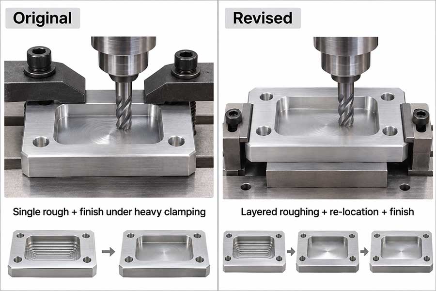
Case C03 used 6061-T6 plate for a 20-part batch, including one first article and 19 subsequent parts. The CNC prototype machining route had two main setups. Initially, the pocket was rough- and finish-milled before the part was flipped for drilling and deburring. The 4.91 mm floor thickness passed its 4.90 to 5.10 mm limit, but measured flatness was 0.23 mm against a 0.15 mm maximum. Clamping restraint and stock removal were the process risks identified in the review.
The revised route kept the approved CAD dimensions and the two main setups. Layered roughing left a 0.30 mm floor finishing allowance. The team used perimeter location and lower, more even clamping force, then unclamped and repositioned the part before floor finishing. The second setup produced the four holes, chamfers, and deburring, followed by cleaning and final inspection. The specification did not change; the machining sequence did.
6.2. Measured First-Article Results
| Characteristic | Specified limit | Recorded first article | Disposition |
| Overall envelope | 100.00 × 60.00 × 12.00 mm; length and width ±0.20 mm | 100.04 × 59.97 × 12.03 mm | Listed envelope values recorded; thickness-axis tolerance not supplied |
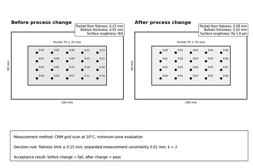
| Pocket floor thickness | 5.00 ± 0.10 mm | 5.02 mm | Pass |
| Pocket floor flatness | ≤ 0.15 mm | 0.08 mm | Pass |
| Four through-hole diameters | Ø6.60 +0.20/0.00 mm | 6.63 to 6.68 mm | Pass |
| Pocket surface roughness | Ra ≤ 3.2 µm | Ra 1.6 µm | Pass |
In the C03 inspection record, floor flatness was evaluated from a CMM point grid at 20°C. Floor thickness was checked with a calibrated micrometer at five points, hole diameters with an internal gauge, and Ra with a stylus instrument. The reported expanded measurement uncertainty for flatness was 0.01 mm (k = 2). For this acceptance assessment, 0.08 + 0.01 = 0.09 mm, below the 0.15 mm limit. This calculation describes the stated inspection conditions, not a universal CMM acceptance rule.
6.3. What the 20-Part Time Comparison Shows
| Time component | Original route | Revised route |
| Programming, once per batch | 36 min | 44 min |
| Setup, per part | 16 min | 13 min |
| Machining, per part | 42 min | 38 min |
| Inspection, per part | 12 min | 14 min |
| 20-part calculation | 36 + 20 × 70 = 1,436 min | 44 + 20 × 65 = 1,344 min |
Across 20 parts, the revised route required 1,344 minutes versus 1,436 minutes for the original, a saving of 92 minutes (about 6.4%). Programming was counted once per batch; setup, machining, and inspection were counted for each part. Multiplying the displayed 106- and 109-minute illustrative totals by 20 would count programming 20 times. These figures are recorded process times, not an estimated price reduction.
The recorded release covers the listed dimensions, geometric checks, and surface measurements only. It does not cover bolt preload, assembly loading, fatigue, impact, corrosion, or long-term dimensional stability. Those claims require separate acceptance criteria and testing.
7. Digital DFM Can Flag Risks, but It Cannot Sign Off the Part
DFM software can flag inaccessible features and small internal corners during an initial DFM analysis. CAM simulation can expose interference between a tool, holder, and modeled fixture, but it cannot predict unclamping distortion that the simulation does not represent. Model based definition can carry product manufacturing information, including tolerances, in the annotated 3D model. STEP AP242 (ISO 10303-242:2025) supports exchange of that information. Whether it arrives intact depends on the CAD export, CAM import, and inspection software in use.
In digital thread manufacturing, the aim is to connect controlled design data with machining plans, production records, and inspection results. Traceable records still cannot prove that a floor measured while clamped will remain flat when released. Use software to flag and document risks, then measure critical characteristics under the agreed conditions.
8. CNC Prototype Release Checklist
| Check | Required answer before release |
| Function | Which faces, holes and fits actually control the assembly? |
| Definition | Do CAD and drawing use one controlled revision? |
| Material | Are alloy, temper and stock form specified? |
| Feasibility | Can the tool and holder access each critical feature? |
| Workholding | Does each setup preserve the required location and support? |
| Geometric controls | Are form, position and surface texture stated separately where needed? |
| Inspection | Are the instrument, datums, state and acceptance rule agreed? |
| Supplier exceptions | Have the technical and quotation differences been resolved? |
| First article | Does the recorded evidence cover the critical release requirements? |
| Decision | Is the documented decision Go, Revise or Hold? |
After approving the drawing, machining route, and inspection plan, the rapid prototyping manufacturing services overview can support the next RFQ and build-planning decision.
9. Questions Engineers and Buyers Actually Ask
9.1. Can I accept a CNC part whose dimensions pass but the surface is warped?
No, not when a required geometric characteristic fails. A passing caliper reading does not override a flatness or position limit. In case C03, the specified pocket-floor flatness was no more than 0.15 mm; the original process produced 0.23 mm. The process had to change before the feature could be accepted.
9.2. What happens when the machine shop cannot confidently hold my GD&T tolerance?
Resolve the capability gap before releasing the job. Ask which feature, datum setup, and inspection uncertainty make the stated tolerance difficult to hold. Agree on a different machining route or approve a controlled drawing change that still protects function. Cutting the part on a best-effort basis while omitting the required measurement is not acceptance.
9.3. Does adding more GD&T make a prototype safer?
Not necessarily. More GD&T controls help only when they define a real functional requirement and can be checked. Extra or ambiguous callouts may add setup and inspection work without improving the prototype. Keep the datum scheme clear for features whose relative position matters.
9.4. Why do quotes change when the quantity increases from a prototype to a small batch?
Programming and preparation are spread over a larger batch, but handling, machining, and inspection still take time on every part. A higher quantity can also justify a different fixture or process, so the quotation must reflect the proposed route. In case C03, the time calculation counted programming once for 20 parts.
9.5. What is first article inspection, and what does it approve?
First article inspection checks an initial manufactured part against the agreed drawing and purchase requirements. An FAI inspection report identifies the characteristics checked and the results recorded. It does not, by itself, validate assembly performance, fatigue life, corrosion resistance, or long-term stability. Case C03 establishes acceptance only for the listed dimensions, geometry, and surface characteristics.
Before issuing the purchase order, give the supplier one controlled drawing revision, the agreed machining route, and the inspection acceptance criteria. Keep any unresolved exception to a functional requirement on Hold.
Ready to Quote Your CNC Prototype?
Upload your STEP file and get a DFM review + quote within 12 hours.
No tooling cost. Minimum 1 part.