

Dewey Wu General Manager & senior mechanical engineer at EPOC CRAFTER, 15 years in design engineering, quality, and metallurgy. Hands-on across CNC machining, metalwork, sheet metal, and prototyping (subtractive + 3D printing).
ABS 3D printing filament is a thermoplastic feedstock used to produce functional parts through fused deposition modeling (FDM). It is suitable for selected housings, brackets, fixtures, and mechanical prototypes, but printed-part performance depends on the ABS grade, build orientation, wall geometry, thermal control, and layer bonding.
A resin datasheet cannot guarantee the strength or heat resistance of an FDM part. This guide explains which ABS grades to specify, how to control printing and warping, and which dimensions and functional checks matter before release.
1. What Is ABS 3D Printing Filament?
ABS stands for acrylonitrile butadiene styrene, a thermoplastic polymer commonly used in molded products and material extrusion 3D printing.
ABS filament is produced by extruding an ABS-based compound into continuous feedstock, commonly supplied on spools for FDM printers. During printing, the nozzle melts the filament and deposits successive roads of material that fuse into a three-dimensional part.
ABS combines three monomer-derived contributions, although their effects depend on the formulation:
- Acrylonitrile: Contributes chemical resistance, thermal stability, and stiffness.
- Butadiene: Provides a rubbery phase that can improve toughness and impact resistance.
- Styrene: Contributes rigidity, processability, and surface appearance.
The formulation and rubber-phase structure determine the balance. The ABS label alone does not identify a fixed strength or temperature rating.
ABS can shrink unevenly as deposited layers cool, causing corner lift, distortion, or cracking. A functional part must meet its dimensional and load requirements after cooling and assembly.
1.1. ABS Material Grades and Commercial Formulations
ABS is a material family, not one grade.
Commercial formulations may differ in rubber content, molecular structure, processing characteristics, modifiers, fillers, and reinforcing materials. These differences affect melt behavior, impact resistance, stiffness, heat resistance, and printability.
ISO 19062-1:2015 provides a designation system for ABS molding and extrusion materials. It identifies material composition, fillers or reinforcements, intended processing characteristics, and selected property classifications.
ASTM D4673-23 separately classifies ABS and certain ABS alloys for molding and extrusion.
These classifications identify material families and grades. They do not certify the performance of a specific FDM filament or printed part.
| ABS material category | Main distinction | Engineering consideration |
| General-purpose ABS | Conventional, unreinforced ABS formulations | Evaluate impact resistance, stiffness, and printing consistency for the selected grade. |
| High-impact ABS | Formulations developed for increased impact resistance | Verify impact results using the same specimen preparation and test method before comparing grades. |
| High-heat ABS | Formulations designed for improved thermal performance | Check the specified thermal test conditions and validate the finished part under load. |
| Flame-retardant ABS | Formulations containing flame-retardant systems | Verify the required fire-test classification and applicable part thickness. |
| Reinforced ABS | ABS compounds containing fibers or other reinforcing materials | Assess directional properties, abrasion, layer bonding, and dimensional stability. |
| ABS/PC blends | ABS combined with polycarbonate | Treat as a separate material formulation with its own processing and performance requirements. |
Neither a high-heat designation nor an impact-modified label proves a particular service-temperature or Z-direction strength limit.
Commercial ABS material properties depend on the exact compound, test route, and conditioning, so a generic label cannot establish an engineering rating.
1.2. ABS Filament Versus ABS Resin Properties
A filament classification does not qualify a printed part.
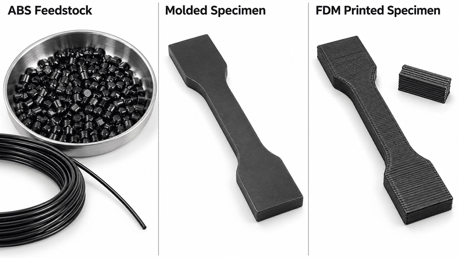
ISO 19062-2:2019 addresses specimen preparation and property determination for ABS molding and extrusion materials. Its standardized specimen procedures do not reproduce every condition present in FDM printing.
Molded test bars and FDM parts follow different thermal and processing histories. Printed roads, voids, and layer interfaces can alter failure behavior.
ISO/ASTM 52903-1:2020 addresses material extrusion feedstock requirements, including material identification, spool characteristics, packaging, and traceability. It provides a basis for controlling the incoming filament, but does not specify a universal ABS nozzle temperature or guaranteed printed-part strength.
Qualification follows three separate decisions:
- Material identity: Which ABS grade or compound is being supplied?
- Printing consistency: Can the filament and equipment reproduce the intended geometry and deposition conditions?
- Part qualification: Does the finished component meet the required dimensional, mechanical, and functional acceptance limits?
A 3D printer filament types guide compares polymer families and feedstock screening. This article addresses the ABS grade, printing window, and finished-part checks.
2. ABS Properties That Actually Matter for Functional Parts
Start with the load path, mating geometry, and operating temperature rather than a generic ABS strength value. Bracket failure often begins around a mounting hole or layer interface.
2.1. Strength, Impact Resistance and Print Direction
Tensile strength, tensile modulus, elongation, and impact strength measure different responses. High tensile modulus indicates resistance to elastic extension; it does not establish notch toughness. A high impact value from one method cannot be substituted for an unnotched test or a result produced under different specimen conditions.
The deposited roads create direction-dependent mechanical behavior. Interfaces loaded normal to the layers may fail differently from paths aligned with the load. XY and Z coupons must not be equated with molded specimens. The 3D printed tensile stress reference explains test definitions; ABS comparisons still need matched specimen conditioning, raster direction, wall count, and fracture observations.
For a bolted bracket, first examine bending at the root, bearing around the holes, stress concentration at corners, and permanent deformation after unloading. A nominal polymer strength value alone cannot confirm bracket load capacity.
2.2. Heat Resistance: Tg, Vicat and HDT Are Different
These measurements answer different questions:
| Property | What it measures | What it does not prove |
| Glass transition temperature, Tg | A change in the response of the amorphous polymer phase over a specified measurement method | Safe operation of a loaded printed part at Tg |
| Vicat softening temperature | Indentation response under a specified load and heating procedure | Continuous-use temperature for a housing or clamp |
| Heat deflection temperature, HDT | Deflection of a specified specimen under a defined bending stress and heating rate | Long-term dimensional stability under the actual part’s load |
ISO 19062-1:2015 uses Vicat and other properties to classify material grades. ISO 19062-2:2019 identifies test procedures for determining material properties. Neither makes one quoted temperature a universal maximum operating temperature for a printed ABS component.
A housing next to a warm circuit board needs an assessment of actual temperature, restraint, duration, wall thickness, and load. A snap feature or bolted joint may creep or lose clamping force before the entire part visibly deforms. Evaluate the finished geometry after a relevant thermal exposure, then inspect the features that perform the mechanical function.
2.3. Chemical Exposure, Aging and Functional Limits
ABS can be suitable for dry indoor mechanical housings, but chemical compatibility is formulation- and environment-specific. Cleaning agents, lubricants, solvents, UV exposure, and repeated temperature changes can alter the result. Acetone, for example, can intentionally soften the surface during finishing; that same sensitivity makes uncontrolled solvent contact undesirable for a dimension-critical part. Do not infer outdoor durability or flame resistance from the letters ABS.
3. ABS Print Settings and Process Window
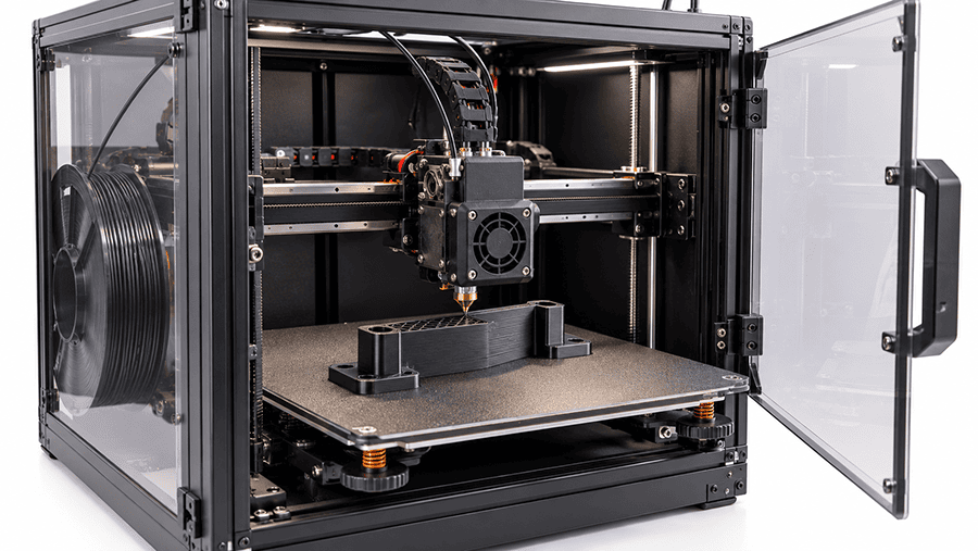
ABS print settings must match the named filament and machine. The FDM 3D printing process depends on extrusion, deposition and cooling, all of which affect fusion and distortion.
3.1. Nozzle, Bed and Chamber Temperatures
A supplier’s suggested nozzle and bed temperatures should be checked against the machine configuration and then tuned on a representative part. A hotter nozzle may improve fusion in one setup but can also increase oozing, surface defects, or degradation risk. A heated bed improves first-layer contact; it does not eliminate thermal stress higher in the build.
A stable enclosure limits drafts and steep cooling gradients. The air temperature inside the chamber is not the same as the nozzle, bed, or polymer temperature. Verify chamber conditions using equipment-suitable measurement, and do not assume every printer’s motors, electronics, fixtures, or printed components are approved for the same internal temperature.
The case in Section 7 used 250°C nozzle, 100°C bed, and 45°C chamber settings for one PolyLite ABS bracket run. Those numbers describe that build only. They are not minimum or maximum specifications for ABS generally, nor values prescribed by ISO 19062-2, ASTM D4673, or ISO/ASTM 52903-1.
3.2. Speed, Cooling, Walls and Build Orientation
Printing speed changes the time available for deposition and road-to-road bonding. Fan settings alter cooling. Wall count and infill influence local stiffness but do not make a hollow or partially filled part equivalent to a solid material test specimen. For a mechanically loaded part, place continuous perimeter paths around critical features where practical, and inspect the likely load path rather than relying on the nominal infill percentage.
Choose orientation around the functional interfaces. A flat-mounted bracket may print accurately on its broad face yet still concentrate tension between layers at an upright feature. A taller orientation may improve one surface but worsen support requirements, dimensional consistency, or strength in another direction. Document the selected orientation before comparing test runs.
4. Why ABS Warps, Shrinks and Delaminates
ABS warping begins when deposited polymer contracts unevenly against the bed, adjacent layers, and structural constraints. Flat first layers can still conceal bow or shifted hole positions after cooling.
4.1. Diagnose the Defect Before Changing Settings
| Observed condition | Plausible mechanism | First inspection or control |
| Corners lift from bed | Thermal contraction exceeds bed adhesion or geometric restraint | Check bed condition, first-layer contact, drafts, footprint and enclosure temperature |
| Tall wall bows | Nonuniform cooling and constrained shrinkage | Measure wall profile and review heat distribution, thickness changes and orientation |
| Layer interface cracks | Stress across a poorly fused or highly constrained interface | Inspect fracture plane, extrusion quality, fan setting and orientation |
| Hole spacing shifts | Local contraction, distortion or print-path compensation | Measure cooled parts, not only the hot build or CAD dimensions |
Do not correct every warped corner with a global scaling factor. First distinguish adhesion loss from differential contraction, cross-section changes, and an unfavorable build direction. DFM design guidelines support the geometry review.
4.2. Measure Features in Their Final Condition
For dimensional checks, specify when the part is measured after removal from the machine and which faces provide the datum. Distinguish overall bow, seating-face flatness, corner lift, and hole-center spacing. Those are not interchangeable measurements. A part that seats after bolt tightening may still carry assembly stress that was absent in its free state.
Set dimensional acceptance limits around the mating function: hole fit, flatness, allowed corner lift, and proof-load displacement. Tolerances and standards help specify inspection language, but they do not supply universal ABS printed-part tolerances.
5. ABS Filament Drying, Storage and Lot Control
Moisture exposure, spool handling, and changing filament cross-section can destabilize extrusion. Choose a drying procedure for the exact filament and dryer rather than copying resin-molding conditions from a classification standard.
ISO/ASTM 52903-1:2020 provides a practical feedstock control baseline. For each batch, its traceability provisions identify the vendor, material, lot number and manufacture date, with unique identification for the feedstock, spool or container. The filament and spool characteristics are tied to applicable equipment specifications, not one mandatory diameter tolerance for all machines.
5.1. Incoming Filament and Build Records
Record the filament product and internal lot identifier, color or modification, spool condition, measured dimensions when relevant, drying and storage practice, and the build setup. Link the part batch to the print settings and inspection results. One changed spool, fan profile, nozzle or chamber condition can explain a shift that would otherwise be blamed on “ABS variation.”
Repeat critical measurements with the same fixtures and inspection conditions. A stable incoming lot does not, by itself, establish printed-part consistency.
6. ABS Fumes, Ventilation and Finishing
ABS printing can release volatile compounds and ultrafine particles. Emissions depend on the compound, temperature, printer, and operating conditions. Odor is not an exposure measurement.
Assess room ventilation and extraction for the specific printer and workstation. Filter type alone does not demonstrate effective capture; airflow, enclosure leakage, maintenance, and the actual emission profile matter.
ABS can be sanded, machined, painted, or smoothed with acetone under suitable safety controls. Vapor smoothing may round edges and change holes or mating surfaces. Surface finishing decisions should therefore include post-process dimensional inspection.
7. Engineering Case: ABS Electronics Mounting Bracket
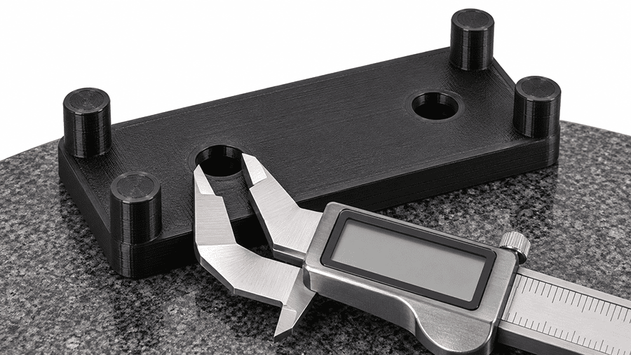
An indoor electronic module needed a bracket mounted to a rigid aluminum support plate. The service condition specified a 15 N downward load from the module and wiring, indoor temperatures from 15°C to 40°C, and a planned two-year service period. The verification described here covered short-term loading and a defined heat exposure; it did not reproduce two years of operation.
7.1. Part Geometry and Print Conditions
The bracket measured 90.00 × 45.00 × 18.00 mm, with 3.00 mm minimum wall thickness. Two 4.30 mm through-holes were located on 60.00 mm centers and secured using M4 bolts, washers and nuts. Four raised pads supported the module. The support plate provided continuous backing, and the fasteners were tightened to 0.35 N·m without relying on printed internal threads.
The material was black, unreinforced Polymaker PolyLite ABS, 1.75 mm filament, identified internally as lot ABS-PL-261009-A. A 0.40 mm nozzle deposited 0.20 mm layers with four perimeters, 50% gyroid infill and six top and bottom layers. The part lay flat with its 90 × 45 mm face on the bed. The print profile used a 250°C nozzle, 100°C bed, 45°C chamber, 35 mm/s outer-wall speed, 55 mm/s infill speed and 0% model fan. Filament was dried at 65°C for four hours before printing; parts rested at 23 ± 2°C for 24 hours after removal.
7.2. Dimensional Checks and Warpage
Three brackets were printed and all three were inspected. The measured results were:
| Part | Flatness (mm) | Max corner lift (mm) | Hole diameters (mm) | Hole spacing (mm) |
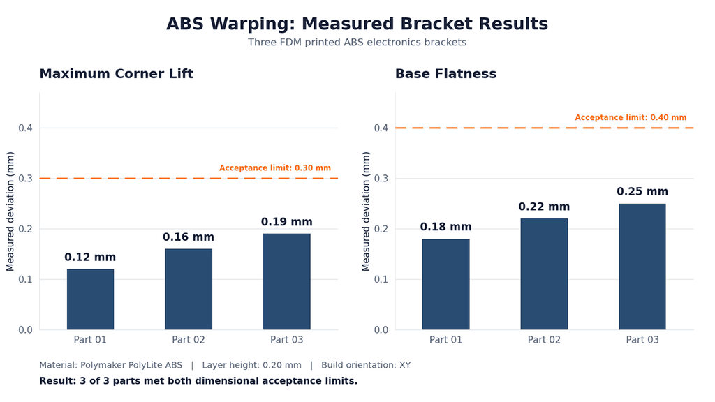
| 01 | 0.18 | 0.12 | 4.31 / 4.33 | 60.06 |
| 02 | 0.22 | 0.16 | 4.28 / 4.32 | 59.94 |
| 03 | 0.25 | 0.19 | 4.34 / 4.30 | 60.09 |
The acceptance limits were flatness ≤0.40 mm, corner lift ≤0.30 mm, hole diameter 4.30 ±0.20 mm, and hole spacing 60.00 ±0.30 mm. The maximum observed spacing deviation was 0.09 mm. All three parts met these stated dimensional limits. Visual inspection reported no through-cracks, delamination or hole-edge defects affecting assembly.
The case used a digital caliper and height gauge with 0.01 mm resolution, a granite reference surface, and supplementary plug-gauge checks. The inspection supports these particular dimensions and features; it does not establish a universal tolerance for ABS FDM printing.
7.3. Static Load, Heat Exposure and Assembly Fit
Each bracket was bolted to a rigid plate and loaded vertically downward at a point 30 mm from the mounting face. The proof load was 40 N for 60 seconds at 23 ± 2°C, giving a nominal applied moment of 1.20 N·m about the mounting face. The highest recorded loaded displacement was 0.75 mm against a 1.00 mm limit. The highest permanent deformation, measured ten minutes after unloading, was 0.08 mm against a 0.15 mm limit.
| Part | Displacement at 40 N (mm) | Permanent deformation (mm) | Minimum assembly clearance (mm) |
| 01 | 0.62 | 0.05 | 0.62 |
| 02 | 0.70 | 0.07 | 0.58 |
| 03 | 0.75 | 0.08 | 0.55 |
All three assemblies then underwent 45 ± 2°C exposure for 24 hours while mounted, followed by two hours of recovery at room temperature. The inspection reported no layer separation, loss of clamping or interference. All recorded minimum clearances remained within the 0.40 to 1.00 mm acceptance range. Accordingly, 3 of 3 brackets passed the stated dimensional, proof-load, thermal-exposure and assembly checks.
The three brackets met the recorded dimensional, static-load, heat-exposure, and clearance limits. The short proof load and 24-hour heat exposure do not establish fatigue endurance or two-year creep performance.
The bracket application belongs to consumer electronics manufacturing, where mounting fit, restrained geometry, and tested function matter more than a generic resin-strength threshold.
8. Choosing ABS for Housings, Fixtures and Functional Parts
ABS suits some indoor housings, fixtures, brackets, and functional prototypes when its heat response, print stability, and final fit meet the application. Outdoor UV exposure, sustained bending, or a demanding fire rating can change that decision.
| Selection question | Engineering decision |
| Is the part mechanically loaded? | Inspect actual load path and build orientation; qualify the component, not just the filament label. |
| Must the part stay flat or align holes? | Test the final cooled geometry and assemble it using the production fastening method. |
| Is heat exposure important? | Check material-specific thermal data and verify performance under the actual load and exposure time. |
| Is a smooth cosmetic finish required? | Consider post-processing effects on fits, sharp edges and dimensions. |
| Will the part be repeated or sourced from another supplier? | Record filament identity, build conditions and acceptance criteria before changing the supply path. |
PLA, PETG, and ASA are alternatives, but none is automatically stronger or more suitable. Compare the actual grade, printer setup, exposure conditions, and required property rather than assigning a universal materials ranking.
An ABS prototype may establish assembly geometry before rapid injection molding. Switching to a molded product still requires independent assessment of the molding grade, shrinkage, surface, and tolerances.
9. ABS Filament Questions Engineers Actually Ask
9.1. Does ABS Need an Enclosure?
An enclosure is strongly useful for controlling drafts and temperature gradients, particularly on larger or tall components. It does not replace first-layer control, machine temperature limitations or workplace ventilation.
9.2. Is ABS Stronger Than PLA or PETG?
There is no reliable universal ranking. Strength depends on the exact commercial grades, specimen preparation, build orientation, test speed and conditioning. Compare the property required by the design using equivalent test conditions, then verify the printed geometry.
9.3. How Do You Prevent ABS Warping?
Stabilize first-layer contact, minimize uneven cooling, choose a favorable orientation and review changes in cross-section. Measure cooled parts to determine whether the improvement fixes critical dimensions rather than only improving appearance.
9.4. Is It Safe to Print ABS Indoors?
Indoor printing requires an exposure-control assessment. Ventilation, local extraction or suitable filtration should be chosen and maintained for the room and equipment; an enclosed printer or absence of odor is not proof of safety.
9.5. What Temperature Can ABS Withstand?
A single temperature cannot answer that question for every ABS grade or printed component. Tg, Vicat and HDT are different measures. For a functional design, qualify the specific printed part under its intended temperature, load and duration.
Keep the named ABS grade, build orientation, settings, final dimensions, and acceptance results together. Those records also support rapid prototyping and low volume production when the same functional interfaces must remain consistent.
Ready to Quote Your CNC Prototype?
Upload your STEP file and get a DFM review + quote within 12 hours.
No tooling cost. Minimum 1 part.
