

Dewey Wu General Manager & senior mechanical engineer at EPOC CRAFTER, 15 years in design engineering, quality, and metallurgy. Hands-on across CNC machining, metalwork, sheet metal, and prototyping (subtractive + 3D printing).
AR500 steel plate and AR400 steel plate need fabrication routes that account for their hardened condition. Thermal cutting changes the edge; bending depends on product, thickness and direction; welding changes local properties and can move mounting features. Decide which faces and holes need finish machining afterward. In EPOC CRAFTER’s 12 mm AR400 liner case, support-region variation reached 1.85 mm after welding and fell to 0.32 mm after correction and milling. The final flatness limit was 0.50 mm. Wear plate fabrication must follow the finished assembly’s requirements, rather than the blank’s initial accuracy.
Plan sheet metal fabrication around the material, joining sequence and final features together. An acceptable cut blank can still need edge preparation, forming trials or machining stock before it becomes an installable component.
1. AR400 vs AR500: Plate Identity and Incoming Acceptance
AR400 steel and AR500 steel describe abrasion resistant steel families with nominal hardness levels around 400 and 500 HBW. The labels do not define one chemistry, toughness level or fabrication procedure. Comparing AR400 vs AR500 steel starts with the product, thickness and delivery condition of each AR400 plate or AR500 plate order. Order abrasion resistant steel plate by that identity; descriptions such as wear resistant steel or steel wear plate leave purchasing details unresolved.
Table 1. Incoming Plate Acceptance
| Incoming information | Establish before release | Fabrication decision |
| Product and plate condition | Producer, commercial grade, material specification and delivery condition | Use matching product guidance; assess substitutions before cutting |
| Thickness and blank | Thickness limits, stock geometry and rolling direction where needed | Select cutting capacity, bend tooling and machining stock |
| Hardness | Product-specific range, test method and applicable location | Accept against the ordered requirement, not the nominal AR number |
| Other required properties | Applicable chemistry, toughness and mechanical requirements | Check service and welding needs that hardness cannot establish |
| Lot traceability | Link the plate, certificate and cut components | Retain material identity through fabrication |
EPOC CRAFTER shop-floor data identify the liner material as 12 mm SSAB Hardox 400, supplied as quenched wear plate, batch HB400-26-081. Incoming hardness was 402 HBW within the project’s 370 to 430 HBW range. The result establishes incoming hardness compliance.
1.1 Hardness Certificates and Material Specifications
ASTM E10-23 and ISO 6506-1:2014 define the Brinell hardness test, not AR grades. Read the mill test report or hardness certificate against the ordered product. An AR400 steel specification or AR500 steel specification must establish the required properties separately from the measurement method.
For AR400 hardness and AR500 hardness checks, retain the HBW designation, test conditions and location. Under ASTM E10-23, HBW 10/3000 uses a 10 mm ball and 29.42 kN force, normally held for 10 to 15 seconds. Surface preparation, thickness and indentation geometry must also meet the method. Incoming Brinell hardness results do not establish hardness beside a later cut or weld.
1.2 What Properties Do Not Tell You About Fabrication
AR400 steel properties and AR500 steel properties help screen wear plate grades, but wear plate hardness alone does not establish impact toughness, bendability or joint strength. Compare abrasion resistant steel grades and wear resistant steel grades at the actual product and service conditions. Higher hardness alone does not justify replacing AR400 in an established forming route.
AR400 heat treatment and AR500 heat treatment also require product-specific decisions. Heating for straightening, forming or stress relief can change the supplied condition. Establish the permitted thermal cycle before adding heat to solve a fabrication problem.
2. Cutting AR400 and AR500 Wear Plate
Select wear plate cutting by the edge you need for the next operation. Cutting AR500 or cutting AR400 to the correct outline does not make the edge ready for bending or machining. Leave final hole production until after welding where the mounting relationship can move.
2.1 Laser, Plasma and Waterjet Cutting
Laser cutting AR500 steel or AR400 steel requires equipment suited to the thickness, piercing and edge requirements. The same laser cutting materials decision applies here: confirm the machine and material, then assess cut quality against the finished part.
Table 2. Cutting Route Decisions
| Cutting route | When to consider it | Check before the next operation |
| Laser | Detailed profiles within the demonstrated material and thickness window | Piercing, dross, taper, thermal effects and finishing stock |
| Plasma | Blanks whose edge allowance accommodates the demonstrated process | Slag, oxide, edge geometry, cracking risk and usable stock |
| Abrasive waterjet | A thermal HAZ is undesirable at the cut | Kerf taper, striations, dimensions and required finishing |
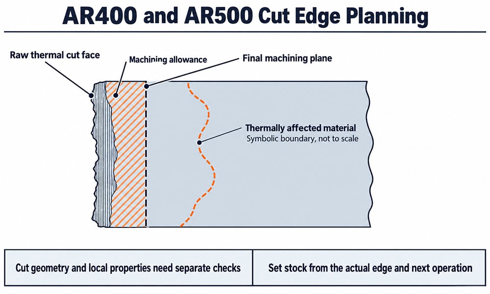
Plasma cutting AR400 and plasma cutting AR500 require review of the thermally affected edge. SSAB’s Cutting Hardox wear plate guidance describes re-quenched and tempered regions in the heat affected zone (HAZ) after thermal cutting. A tool crossing that edge may encounter different hardness conditions. Waterjet cutting AR400 or waterjet cutting AR500 avoids a thermal HAZ, but not dimensional inspection or finishing.
2.2 Cut Edge Quality and Machining Stock
ISO 9013:2017 with Amendment 1:2024 addresses thermal-cut geometry and quality, including perpendicularity or angularity tolerance, u, and mean profile height, Rz5. Specify the required ranges and thickness conditions. A thermal cut edge accepted under ISO 9013 still needs separate HAZ hardness or toughness checks when required.
The liner route reserved 1.0 mm per side on the plasma-cut outline, removed dross and oxide, eased sharp edges and milled the locating edges. Mounting holes were not plasma cut. Machining allowance on another blank must accommodate its edge condition, dimensional movement and final tool engagement.
3. Bending AR400 and AR500 Plate
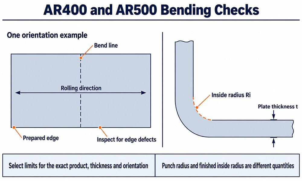
Before bending AR400 or bending AR500, confirm the producer’s limits for the exact product, thickness and bend orientation. Check press capacity, die opening, punch geometry and the complete sequence. Bending abrasion resistant steel to a permitted radius still needs a capable machine and setup.
3.1 Bend Radius, Orientation and Edge Condition
Select the AR400 bend radius or AR500 bend radius from the product guidance. Record the inside radius and bend line’s relationship to rolling direction. Distinguish the recommended punch radius from the finished inside radius. General sheet metal bend radius calculations explain developed length and springback; mild-steel radius tables cannot qualify hardened wear plate bending.
AR400 forming and AR500 forming need sound edges and a material-specific tooling window. Remove defects that could initiate bend cracking, establish springback compensation with the intended stock and inspect nearby holes afterward. Outside the permitted window, assess a larger radius or segmented design. Heating the bend needs separate product-specific assessment. The liner case used flat plate without bending.
4. Welding AR500 Steel and AR400 Plate
Welding AR500 steel and welding AR400 steel require hydrogen control, a suitable thermal cycle and a plan for restraint and distortion. Locate the weld relative to the wear face and define its load-carrying function before selecting consumables and inspection requirements.
4.1 WPS Qualification and Thermal Controls
An AR400 welding procedure or AR500 welding procedure must cover the actual materials, thicknesses, process and joint. ISO 15614-1:2017 with Amendment 1:2019 addresses procedure qualification by testing. The WPS sets production variables; the supporting WPQR establishes the tested basis and qualification range. Experience welding AR400 does not establish a procedure for every AR500 product.
AR400 preheat and AR500 preheat decisions depend on product guidance, combined thickness, hydrogen, heat input, restraint and starting temperature. Minimum preheat and maximum interpass temperature control different risks. Raising temperature without considering the hardened condition can create another problem while reducing cracking risk.
EPOC CRAFTER shop-floor data for the 12 mm liner recorded 22 to 30 °C before welding, without additional preheat, and 45 to 120 °C between passes. At 24 V, 190 A and 300 mm/min, a MAG efficiency factor of 0.80 gives Q = 0.80 × 24 × 190 × 60 ÷ (1000 × 300) = 0.73 kJ/mm. These conditions belong to this joint route, not all AR400 or AR500 welding.
4.2 Joining Wear Plate to Mild Steel
Welding AR500 to mild steel and welding AR400 to mild steel require review of both materials and the connection load path. Select filler strength, weld size and placement through the applicable design and procedure. Matching filler hardness to plate hardness is not, by itself, a connection design requirement.
The liner’s 8 mm S355JR backing lugs were joined to 12 mm Hardox 400 using MAG process 135, 1.0 mm ER70S-6 wire and 82/18 argon/CO₂. Double-sided fillet welds had a nominal 5 mm leg. Short alternating runs and a diagonal sequence distributed heat while the fixture restrained the assembly. The welds were behind the wear face, outside direct abrasion.
4.3 Weld Imperfections and HAZ Verification
For welding wear plate, specify weld imperfections, heat affected zone (HAZ) properties and dimensions separately. ISO 5817:2023 gives imperfection quality levels B, C and D for applicable fusion welds, excluding beam welding. The drawing, contract or responsible designer selects the level. Check HAZ softening and other local property requirements separately from weld imperfections.
The liner project used visual examination following ISO 17637:2016 and specified ISO 5817:2023 level C visual criteria. Weld legs measured 5.1 to 5.7 mm against 5.0 ±1.0 mm; no surface cracks were observed. Local HAZ hardness was 360 to 388 HBW under ISO 6506-1:2014. Electrode handling and procedure variables need separate assessment when shielded metal arc welding replaces MAG.
5. Machining AR400 and AR500 After Cutting or Welding
Machining AR500 or AR400 requires stable workholding and attention to the region being cut. Plan wear plate machining around the component’s size, support and tool reach when assessing CNC machining capabilities.
5.1 Drilling AR500 Steel and AR400 Steel
For drilling AR500 steel or drilling AR400 steel, assess a thermally cut pilot separately from drilling solid plate. The pilot can leave altered material in the drill’s path. Support the plate close to the hole, control breakthrough and evacuate chips. Choose direct drilling, pilot drilling and enlargement to suit the tool and local condition.
The liner route drilled to 16 mm with a coated carbide drill, then enlarged the holes to 18 mm with a carbide tool. The 18 mm operation used approximately 35 m/min, 620 rpm, 0.12 mm/rev and water-soluble coolant. Four holes required about five minutes of in-machine cutting time per component. These project values are not universal settings for drilling AR500 or drilling AR400.
5.2 Machinability, Milling and Tapping
AR400 machinability and AR500 machinability depend on product, local condition, tool and setup. Milling AR400 or milling AR500 needs supported engagement and usable stock. Check tool wear together with hole quality and surface condition, rather than waiting for the tool to stop cutting.
Tapping AR400 and tapping AR500 add tool-breakage and recovery considerations. A clearance hole with an accessible nut can simplify replacement where the design permits. Machining abrasion resistant steel should create the required mounting features while preserving the functional wear section.
6. Final Datums, Mounting Faces and Critical Holes
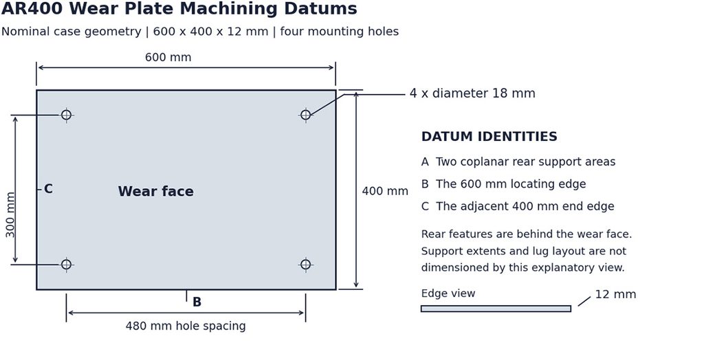
EPOC CRAFTER shop-floor data cover 24 replaceable AR400 wear plate liners, each approximately 600 × 400 × 12 mm, for a limestone chute handling particles around 10 to 60 mm. Sliding abrasion was accompanied by intermittent impact. Backing lugs carried installation clamping forces; four clearance holes accepted M16 grade 8.8 bolts.
The steel plate fabrication route placed wear plate machining after welding, cooling and mechanical correction. The fixture was released below 40 °C; no overall post-weld heat treatment was used. Datum A comprised two coplanar rear support areas, B the 600 mm locating edge and C the adjacent 400 mm end edge.
Table 3. Support Region Through Fabrication
| Stage | Support-region peak-to-valley variation over 600 × 400 mm | Process implication |
| After cutting and edge finishing | 0.65 mm | Initial blank geometry was not the final acceptance condition |
| After lug welding and free cooling | 1.85 mm | Welding increased variation in the mounting region |
| After mechanical correction | 0.72 mm | Correction alone did not reach the 0.50 mm final limit |
| After support-area finish milling | 0.32 mm | The finished support surface met the 0.50 mm limit |
The stages used the same platform scanning approach. Final support-surface flatness was checked on a three-point setup with a 0.01 mm resolution dial indicator. Correction followed by local milling brought the support surface within its mounting limit.
6.1 As Welded Tolerances and Final Machined Features
ISO 13920:2023 provides general welded-construction tolerances: classes A to D for lengths and angles and E to H for straightness, flatness and parallelism. Identify the applicable general class and separately specify critical machined features. Final machining tolerances and inspection must follow the mounting faces, hole position and datum relationship on the drawing.
Table 4. Final Features and Acceptance
| Final characteristic | Requirement | Case result | Decision |
| Support-surface flatness | ≤0.50 mm over 600 × 400 mm | 0.32 mm | Met the limit |
| Four mounting holes | Ø18.0 ±0.2 mm | 17.96 to 18.08 mm | Within 17.80 to 18.20 mm |
| Long-direction hole spacing | 480.0 ±0.5 mm | 479.82 to 480.21 mm | Within 479.50 to 480.50 mm |
| Short-direction hole spacing | 300.0 ±0.5 mm | 299.84 to 300.19 mm | Within 299.50 to 300.50 mm |
| Hole position relative to A, B and C | Ø1.0 mm | Maximum 0.68 mm | Met the positional limit |
All 24 components were accepted and delivered, including two that passed after rework; none were scrapped. Changing to AR500 wear plate, a different weld layout or greater restraint requires another process assessment. Geometry and hardness do not establish connection load capacity.
7. Wear Liners and Replaceable Plate Components
A wear liner plate must fit its supports and remain replaceable. Specify the wear face, fastening access and replacement clearance when selecting AR400 wear plate or AR500 wear plate. For abrasion resistant liners, local impact and attachment loads matter alongside wear plate hardness.
Table 5. Wear Liner Applications
| Application | Fabrication decision |
| Bucket liners | Check formed fit, impact and attachment location before selecting the grade |
| Chute liners | Control support contact, flow transitions and replaceable hole patterns |
| Hopper liners | Resolve panel fit, corner geometry and fastening access |
| Crusher wear plates | Assess the component’s impact, support and connection loads |
| Conveyor wear plates | Keep transitions and fasteners clear of the conveying path |
| Steel dump truck bed liners | Assess forming, attachment layout and added mass for the selected plate |
Steel wear liners made from wear resistant steel plate need a product and installation specification, not only a hardness designation. Include replacement access before fixing the attachment layout.
8. AR400 and AR500 Fabrication Questions
8.1 What Is AR400 Steel, and How Does It Differ from AR500?
AR400 and AR500 are nominal hardness families around 400 and 500 HBW. Compare the products’ toughness, forming limits and fabrication guidance before substituting one for the other. A purchase order needs more than the AR designation.
8.2 Can You Weld AR500 and AR400 Plate?
Yes, using a procedure suited to the product and joint. The weld’s location and function determine the required checks, including local properties, weld imperfections and final dimensions.
8.3 How Should AR400 and AR500 Welding Procedures Be Selected?
Select a WPS with the required qualification range and product-specific thermal limits. Check both materials in a dissimilar joint; a procedure used for another plate thickness or attachment does not automatically cover yours.
8.4 Can You Bend AR400 and AR500 Plate?
Both families include bendable products under stated conditions. Confirm thickness, orientation, inside radius and tooling against the producer’s guidance. A permitted material radius does not establish your press capacity or setup.
8.5 How Do You Cut AR500 Steel and AR400 Plate?
Laser, plasma and abrasive waterjet are potential routes. Include finishing and the next operation in the comparison. A thermally cut pilot hole may leave material needing a different drilling approach from solid plate.
8.6 How Do You Drill AR400 and AR500 Steel?
Use suitable tooling, rigid support and parameters matched to the local material condition. Check thermally affected areas separately. Establish final hole diameter and location after operations that can move the component.
9. Wear Plate Fabrication RFQ Checklist
Compare custom wear plates at the same delivery condition. AR400 fabrication and AR500 fabrication quotes should distinguish cut blanks from welded, machined components. Wear resistant steel fabrication costs also include edge finishing, tooling, setup and inspection scope.
Table 6. Wear Plate Fabrication RFQ Inputs
| RFQ input | State before production planning |
| Material | Commercial product, condition, thickness, permitted substitutions and lot traceability |
| Service | Abrasion, impact, operating temperature and replacement requirements |
| Cutting and forming | Required edge, machining allowance, bend orientation and product-specific limits |
| Welding | Connection materials, joint design, procedure basis, imperfection level and inspection scope |
| Final features | Datums, mounting faces, hole sizes, position requirements and inspection condition |
| Delivery | Quantity, protection, rework acceptance and required inspection outputs |
When ordering custom AR400 plate or custom AR500 plate components, state the AR400 steel specification or AR500 steel specification alongside the final feature requirements. AR400 steel fabrication and AR500 steel fabrication need one agreed route from material acceptance to installation geometry. Discuss end to end manufacturing with those requirements together so the abrasion resistant steel fabrication quote covers the finished part.
Ready to Quote Your CNC Prototype?
Upload your STEP file and get a DFM review + quote within 12 hours.
No tooling cost. Minimum 1 part.