

Dewey Wu General Manager & senior mechanical engineer at EPOC CRAFTER, 15 years in design engineering, quality, and metallurgy. Hands-on across CNC machining, metalwork, sheet metal, and prototyping (subtractive + 3D printing).
Shielded Metal Arc Welding, or SMAW, is only one step in a welded fabrication that still needs machined datums, bores or mounting faces. The weld can pass its procedure and inspection requirements while the assembly still bows, shifts or consumes the stock needed for finish machining. For engineers and buyers, the practical job is to connect weld joint preparation, the welding procedure specification, distortion control, weld inspection and post weld machining before production starts. ISO 4063:2023 identifies SMAW as manual metal arc welding, process 111, but process 111 does not define the electrode, current, polarity, groove geometry or final dimensional acceptance.
1. What Is Shielded Metal Arc Welding?
Shielded Metal Arc Welding is a manual arc welding process that uses a consumable, flux covered welding electrode. MMA welding and stick welding are common names for the same process. The welding arc forms between the electrode and workpiece. The electrode and local base metal melt into the weld pool, while the electrode coating produces shielding gases and slag. In shop language, the covered electrode may also be called a welding rod. A basic SMAW equipment set includes a welding power source, welding electrode holder, work lead and the selected covered electrode.
ISO 4063:2023 gives the formal process identity. Manual metal arc welding is reference number 111, and the standard maps the US term Shielded Metal Arc Welding to that process. Use ISO 4063-111 when a drawing, WPS or production record needs an unambiguous process reference. Do not read more into the number. It does not set welding amperage, arc voltage, welding polarity, electrode classification, material thickness or weld acceptance criteria.
| Term | Meaning in this article | Engineering use |
| Shielded Metal Arc Welding, SMAW | Common US process name | Main topic and primary search term |
| Stick welding | Common shop term for SMAW | High volume synonym, useful in buyer language |
| MMA welding | Manual metal arc welding | International terminology |
| ISO 4063-111 | Manual metal arc welding process reference | Drawing, WPS and production document identification |
For assemblies that combine cutting, forming and welding, the welded sheet metal fabrication page places weld inspection and dimensional checks inside the broader production route.
2. What the SMAW Welding Process Changes in a Fabricated Part
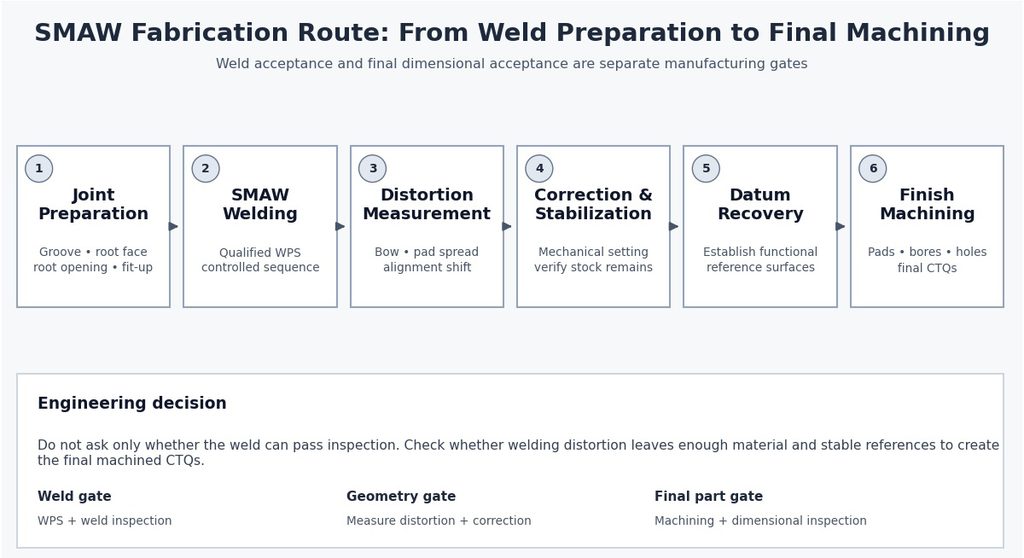
The shielded metal arc welding process changes both the joint and the geometry around it. SMAW is manual, so arc length and travel remain operator controlled within the WPS. Local heating expands the joint area; cooling contracts the weld metal and adjacent base material while the rest of the weldment restrains that movement. On larger weldments, that movement can appear as weld shrinkage, angular change, longitudinal bow, pad tilt or feature shift. Welding heat input, sequence, restraint and joint location influence the result. Residual stress can remain after cooling, but it is not the same thing as geometric distortion. A qualified welding procedure controls the weld process; it does not guarantee final flatness or datum stability.
The EPOC CRAFTER case used in this article was an ASTM A36 machine base measuring 820 × 520 × 168 mm. It is a welding fabrication with both welded and finish machined features. The structure used a 16 mm base plate, 20 mm top pads and 100 × 50 × 6 mm HSS crossmembers. The assembly required four finish machined mounting pads, two Ø18 H7 locating holes at a 460.00 mm nominal center distance, an M16 mounting pattern and controlled pad geometry. These are functional features, so the fabrication welding route had to protect enough stock to create them after welding.
Immediately after welding, the frame showed 2.1 mm of top pad elevation spread, 1.6 mm of base plate bow over 820 mm and 1.4 mm of diagonal difference. The welds still had to be judged against their own acceptance route. The dimensional problem was separate: would the weldment still clean up to the final machined CTQs?
3. Welding Electrodes, Polarity and WPS Control
ISO 2560:2020 classifies covered electrodes and deposited weld metal for manual metal arc welding of non alloy and fine grain steels. It is a welding consumables classification standard, not a universal rule for every SMAW electrode family. A stick welding electrode for stainless steel, cast iron, nickel alloy or aluminum may fall under a different consumable specification. The standard uses two systems. System A is based on yield strength and 47 J impact energy. System B is based on tensile strength and 27 J impact energy, with an optional supplemental 47 J requirement.
| Item | System A | System B | What the buyer should do |
| Primary strength basis | Yield strength | Tensile strength | Read the system letter before interpreting the strength symbol |
| Impact basis | 47 J average | 27 J average, optional 47 J supplement | Do not compare impact symbols across systems without the system context |
| Designation | ISO 2560-A | ISO 2560-B | Keep each designation complete; do not mix A and B symbols |
A designation such as ISO 2560-A-E 46 3 1Ni B 5 3 H5 carries information about strength, impact class, deposited metal chemistry, electrode coating, current capability, welding positions and diffusible hydrogen class. H5 is a diffusible hydrogen classification under specified test conditions. It is not a guarantee that a production joint will not crack. Parent material, restraint, joint geometry, heat input, preheat, interpass control and electrode handling still matter.
The case used AWS A5.1 E7018 H4R as the low hydrogen electrode, with 3.2 mm electrodes for root and smaller fillets and 4.0 mm electrodes for fill and cap passes. The SMAW WPS called for DCEP, 1F and 2F fillets, and 1G groove welding at the HSS splices. Those values belong to WPS-SMAW-CS-07 Rev. C. They are not a generic parameter table for stick welding. Welding current, polarity, arc length, travel speed and heat input have to stay inside the applicable procedure and qualification range.
4. Weld Joint Preparation and Procedure Qualification
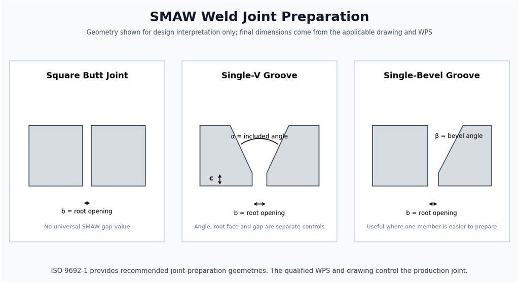
Weld joint preparation sets the geometry presented to the arc. For a buyer, the useful question is not the joint type alone but what the WPS and drawing actually require. A groove weld may need a defined groove angle, bevel angle, root face, root opening, backing condition and allowable mismatch. ISO 9692-1:2013 provides recommended square, single V, single bevel, U and J preparations for steel welding. Those dimensions belong to specific configurations; the standard does not prescribe one universal SMAW bevel.
The machine base used fillet welds for HSS to base and pad to HSS joints, plus complete joint penetration groove welds at two HSS splices. The splice used a single V welding bevel with a 60° included angle, 1.5 mm root face and 2.5 mm root opening. Fillet joints were held at no more than 1.0 mm local gap. Those dimensions are case data. They should not be copied into another weld joint design without checking its material, thickness, access, position and WPS.
The welding procedure specification answers a different question. ISO 15614-1:2017 with Amendment 1:2019 qualifies a preliminary WPS through a representative procedure test, examination and testing, then records the results and qualification range in the WPQR. That weld procedure qualification can depend on parent material group, thickness, deposited weld metal thickness, welding process, welding positions, joint configuration, backing, filler metal, current type, polarity, heat input, preheat, interpass temperature and PWHT. These welding essential variables have to remain inside the applicable qualification range.
A WPS and PQR therefore cannot be reduced to the statement ‘we use E7018 on carbon steel.’ The actual production variables still have to fall within the qualified range. The standard also distinguishes Level 1 and Level 2 procedure tests. Where the application standard or contract does not specify a level, the uploaded technical source identifies Level 2 as the default under this edition.
When drawing decisions are still open, the DFM guidelines for welded assemblies are a useful place to decide which locating faces and tolerance critical features should be created after joining rather than before it.
5. Weld Distortion, Fixturing and Machining Stock
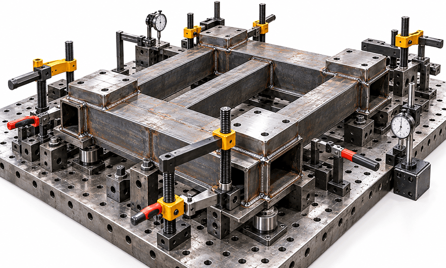
Welding distortion control starts before the arc is struck. Weld fixturing, tack locations, welding sequence and clamp release determine how the structure is restrained while the joint heats and cools. The welding fixture located the base plate on six hardened supports with two datum pins and one side stop. HSS crossmembers used bridge clamps. The top pads used screw clamps and 1.5 mm machining shims to protect stock for the later facing operation. A welding jig or fixture that only holds fit up but ignores later datum recovery can still leave the weldment short of usable machining stock.
Fit up used 25 mm tack welds at both ends and the midpoint of each HSS member. Opposing joints were tacked before production welding. The weld sequence started at the center and moved outward in mirrored pairs, alternating opposite sides of each crossmember. Longer fillets used 90 to 120 mm segments with a short backstep technique. These are project controls, not universal SMAW rules.
| Case measurement | After welding | After correction | Decision meaning |
| Top pad elevation spread | 2.1 mm | 0.70 mm | Correction restored enough stock for pad facing |
| Base plate bow | 1.6 mm over 820 mm | 0.45 mm over 820 mm | Bow was reduced before establishing machining datums |
| Diagonal difference | 1.4 mm | 0.8 mm | Frame geometry was checked before CNC setup |
The pilot route had reached 3.2 mm maximum pad elevation spread and 2.4 mm base bow. Two of six pilot frames needed weld build up before machining because weld distortion had consumed too much machining allowance. After the fixture, sequence, clamp release and correction route changed, all 24 production frames retained at least 1.2 mm of machining stock on every pad. Weld related dimensional rework fell from 2 of 6 pilot frames to 0 of 24 production frames.
A separate EPOC CRAFTER weld distortion and machining sequence case shows the same planning issue with a different joining process: joining can move the datum even when the final dimensional fix belongs in machining.
6. Weld Inspection Before Machining
Finish machining should not hide an unresolved weld problem. ISO 17637:2016 gives a structured visual weld inspection method before welding, during welding, on the finished weld and after repair. That welding inspection route starts with the prepared joint. Before welding, check the preparation dimensions, cleanliness, positioning and fit up against the WPS, drawing or other applicable requirement. Different welding inspection standards or application codes may set the acceptance criteria, so the inspection method and the acceptance limit must not be treated as the same thing.
For the finished weld, visual testing can cover profile, excess weld metal, weld width, accessible root condition, fillet dimensions and visible discontinuities. Surface checks can reveal cracks, porosity, undercut and some penetration problems. Suspected lack of fusion or buried discontinuities may require other NDT because visual testing cannot prove that internal defects are absent. ISO 17637 defines the visual testing method; the applicable product standard, application standard, drawing or agreed acceptance criteria determine whether the observed condition is acceptable.
The case used 100% visual inspection after slag removal. Three isolated undercut locations measured 0.3 to 0.5 mm deep, and one 18 mm slag line appeared at a cap pass restart. The undercut was blended and reinspected. The slag line was ground out and rewelded before magnetic particle testing on the two complete joint penetration splice welds. No dimensional machining started until the required repair and weld inspection route was complete.
EPOC CRAFTER’s weld inspection and quality documentation page covers the QMS context for weld inspection, material records and dimensional checks.
7. Post Weld Machining and Datum Recovery
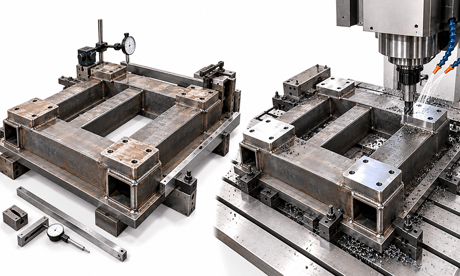
Post weld machining is where fabrication and machining become one dimensional control route. The machine base intentionally left four top pads, two precision locating holes, the M16 mounting pattern and one side datum face for machining after welding. The top pads carried +2.0 mm stock and the side datum face +1.5 mm. The locating holes were drilled undersize at Ø16.5 mm before final boring and reaming.
Setup 1 supported the base underside on three points and face milled the four top pads. Setup 2 then used the machined pad reference as Datum A, the finished side face as Datum B and one locating hole as Datum C. The remaining locating hole and M16 pattern were produced from that recovered datum system. This is the key planning point for weldment machining: do not ask a preweld feature to preserve a relationship that the weld cycle is likely to move.
Final requirements included pad height 165.00 ±0.10 mm, Ø18 H7 locating holes, 460.00 ±0.05 mm hole center distance, four pad flatness 0.10 mm and locating hole position Ø0.10 mm relative to A|B. The finished batch measured 164.96 to 165.04 mm pad height, Ø18.012 and Ø18.015 mm locating holes, 459.98 mm center distance, 0.07 mm four pad flatness and Ø0.07 mm locating hole position. All 24 assemblies passed final weld, dimensional and CMM inspection.
When the weldment still needs precision bores, datum faces or mounting pads, post weld CNC machining is the downstream operation that establishes those final CTQs.
Final CTQs should then be released against manufacturing tolerances and inspection standards rather than against the weld process number or a generic welded tolerance.
8. SMAW Fabrication RFQ Checklist
An RFQ that says only ‘SMAW required’ identifies the process but leaves most production decisions unresolved. For a welded assembly with machined CTQs, use the checklist below to decide which requirements belong on the drawing, purchase order or welding package.
| RFQ item | Define or confirm | Why it matters |
| Process and material | SMAW / ISO 4063-111 where applicable; material grade, product form and thickness | Separates process identity from material and thickness qualification |
| Weld joint design | Fillet or groove weld; groove angle, root face, root opening, backing and fit up where functional | Prevents a vague ‘standard groove’ from controlling production |
| Welding consumable | Applicable electrode classification and handling requirement | A welding rod trade name alone does not define the consumable requirement |
| WPS and PQR | Applicable welding procedure specification, WPQR/PQR and qualification range | Confirms that the actual material, thickness, position and variables are covered |
| Distortion plan | Welding fixture, sequence, dimensional checkpoints, correction plan and machining allowance where needed | Protects stock and datum recovery |
| Welding inspection | Visual inspection stage, agreed weld acceptance criteria and additional NDT where required | Separates visible weld acceptance from internal or dimensional verification |
| Post weld machining | Features left for finish machining, datum sequence, CTQs and surface finish | Defines which geometry is created after welding |
| Final records | Required weld records, material records and final dimensional inspection | Gives procurement a traceable acceptance package |
9. SMAW vs MIG, TIG and FCAW in Fabrication
SMAW is strongest where portability, access and independence from external shielding gas matter. Common applications include field repair, structural work and carbon steel welding. Manual deposition, electrode changes and slag removal become bigger constraints on long repetitive shop welds or automated production.
When you compare stick welding with MIG, TIG, GMAW or FCAW, do not ask which process is simply ‘better.’ Check the joint, welding position, environment, production volume, qualification basis and downstream dimensional plan. Vertical or overhead stick welding also cannot be assumed to be covered just because a WPS was qualified in another position.
A faster wire fed process can change deposition rate and production economics, but it does not remove the need for weld joint preparation, heat input control, weld distortion control, weld inspection or post weld machining. The manufacturing route still has to protect the final function.
10. FAQ
10.1 Are SMAW, stick welding and MMA welding the same process?
Yes. SMAW, stick welding and MMA welding refer to the same manual metal arc welding process. ISO 4063:2023 uses Manual metal arc welding as the primary designation and reference number 111. Stick welding is the common shop term.
10.2 How should a designer control weld distortion in a welded structure?
Start with fit up, weld fixturing, tack strategy, welding sequence, restraint, thermal control and a measured correction plan. Do not rely on welding parameters alone to hold machined CTQs. The required method changes with geometry, joint layout, material and production route.
10.3 Should finish machining be done after welding?
For features whose final relationship can move during welding, finish machining after welding is often the safer route. Leave enough machining allowance, measure the weldment after welding and correction, then create the final datum system and CTQs. Some robust parts can finish before welding, so the decision still depends on stiffness, weld layout and tolerance.
10.4 What should a visual weld inspection look for before machining?
Check the prepared joint and fit up before welding, interpass cleanliness during welding, then the finished weld for profile and visible discontinuities under the applicable acceptance criteria. Visual testing can identify surface conditions, but it does not prove that buried discontinuities are absent or that final machined dimensions are correct.
10.5 What do WPS and PQR actually prove?
A WPS defines the production procedure. The supporting WPQR or PQR records the procedure test and the resulting qualification range. Qualification does not approve every SMAW condition, and it does not guarantee that a weldment will remain dimensionally stable after welding.
Release the Welding and Machining Plan Together
For a fabricated part with machined CTQs, decide the post weld datum and inspection route before the WPS is released. The EPOC CRAFTER machine base did not try to hold final Ø18 H7 locating holes or finished pad geometry through welding. The route controlled the weldment, corrected measured distortion, preserved machining stock and then created the final geometry from recovered datums. That is the useful procurement test for SMAW fabrication: the weld procedure must be qualified, the weld must be inspected, and the complete welding and machining route must still have a credible path to the drawing CTQs.
Ready to Quote Your CNC Prototype?
Upload your STEP file and get a DFM review + quote within 12 hours.
No tooling cost. Minimum 1 part.
