

Dewey Wu General Manager & senior mechanical engineer at EPOC CRAFTER, 15 years in design engineering, quality, and metallurgy. Hands-on across CNC machining, metalwork, sheet metal, and prototyping (subtractive + 3D printing).
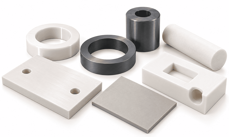
Engineering ceramics can be machined to precise features, but the useful process decision starts with the ceramic grade and its condition before machining. Green alumina, partially fired material, fully sintered zirconia, and machinable glass ceramic do not present the same manufacturing problem. Geometry, critical feature type, grinding sequence, surface texture, edge condition, and inspection method determine whether a drawing is practical. This guide focuses on engineering and procurement decisions for technical ceramics: material selection, pre-fire versus post-fire machining, ceramic grinding, tolerances, surface integrity, additive manufacturing, and a quote-ready RFQ package.
1. What Changes When the Material Is an Engineering Ceramic?
Engineering ceramics, advanced ceramics, technical ceramics, industrial ceramics, and structural ceramics overlap in supplier language, but the family label is not enough for a manufacturing decision. A buyer needs the exact grade, fired state, functional surfaces, and acceptance method. Precision ceramics are selected because specific ceramic properties matter in service, not because “ceramic” is inherently better than metal or polymer.
The properties of ceramics that usually drive selection include ceramic hardness, ceramic wear resistance, ceramic corrosion resistance, electrical behavior, ceramic thermal conductivity, and other ceramic mechanical properties. Those same properties can make material removal more demanding. A hard, brittle surface does not redistribute local tensile stress around a chip, scratch, pore, or machining flaw the way a ductile metal can.
Material selection should stay tied to function. EPOC CRAFTER’s material properties guide supports comparisons between engineering ceramics, metals, and engineering plastics.
Material selection table
| Material | Why choose it | Manufacturing implication |
| Alumina ceramic | Electrical insulation, wear resistance, chemical stability, broad industrial availability | Fully sintered alumina usually needs abrasive finishing on critical faces and bores |
| Zirconia ceramic | Higher fracture toughness and mechanical damage tolerance than many oxide ceramics | Grinding remains feature-sensitive; local stress and edge condition still matter |
| Silicon carbide ceramic | High hardness, wear and corrosion resistance, strong thermal performance | Post-fire stock removal is demanding; form major geometry before final densification when the route allows |
| Silicon nitride ceramic | Strength, toughness, wear resistance, and thermal shock resistance | Reserve precision finishing for functional interfaces and features that need final control |
| Aluminum nitride ceramic | Electrical resistance combined with high thermal conductivity | Flatness, thickness, clean surfaces, and interface geometry often dominate the drawing |
| Boron nitride ceramic | High-temperature electrical applications and machinability in specific grades | Grade and pressing direction matter; some BN grades are intentionally machinable |
| Macor ceramic / machinable glass ceramic | Prototype and low-volume parts where conventional machining access is valuable | Conventional turning, milling, drilling, and grinding are feasible with material-specific practice |
Supplier data sheets also use plural forms such as alumina ceramics, zirconia ceramics, silicon carbide ceramics, silicon nitride ceramics, aluminum nitride ceramics, and boron nitride ceramics. Treat those as material-family language, then lock the actual grade on the RFQ. Common comparison questions such as alumina vs zirconia, zirconia vs alumina, and silicon carbide vs silicon nitride should be resolved against the load case, environment, interface function, and available manufacturing route rather than by a generic winner.
2. Machine Before Firing or After Sintering?
The material state usually changes cost and risk more than the name of the CNC machine. Green machining removes material from an unfired body while it is easier to cut. Partially fired or bisque machining adds stiffness before final densification. Fully sintered machining avoids later sintering shrinkage, but the dense ceramic is harder and more brittle and often shifts final feature creation toward diamond grinding, lapping, or other abrasive processes.
The broader ceramic manufacturing process can include ceramic pressing, ceramic forming, ceramic injection molding, ceramic molding, binder removal, ceramic sintering, and final ceramic processing. In advanced ceramic manufacturing, those steps determine the blank condition before precision ceramic machining begins. The ceramic sintering process is therefore part of the dimensional strategy, not a background heat-treatment note.
| Material state | Use it when | Main risk | Buyer decision |
| Green | Substantial stock can be removed before densification and final dimensions can tolerate the supplier’s validated shrinkage model | Sintering shrinkage, distortion, fragile green edges | Identify which features may move and which need post-fire correction |
| Partially fired | More rigidity is needed than green material while some pre-final shaping is still economical | Final firing can still move size, flatness, and feature position | Treat dimensions as provisional until the final firing route is complete |
| Fully sintered | Final size, flatness, bore geometry, or surface condition must be established after densification | Chipping, grinding damage, fixture-induced bending, higher finishing effort | Reserve post-fire work for functional features and define inspection |
This route split is supported by established technical-ceramic manufacturing practice: green machining is used before sintering to reduce difficult post-fire stock removal, while fired ceramics are finished by grinding and polishing when the final feature requires it. A hybrid route is often the practical answer.

3. Ceramic Machining, Grinding, Lapping, and Drilling
Ceramic machining is not one process. A machinable ceramic such as Macor ceramic can support conventional ceramic milling, ceramic turning, and ceramic drilling. Hard fired materials such as dense alumina, silicon carbide, or silicon nitride may require ceramic grinding, jig grinding, ultrasonic assistance, or another abrasive route. Supplier pages may call the work ceramic CNC machining, CNC ceramic machining, machining ceramics, ceramic cutting, or precision ceramic machining. The label does not prove the same capability on every grade and fired state.
Where conventional subtractive work is relevant, the supplier’s CNC machining capabilities should be reviewed separately from the ceramic-specific grinding and damage-control plan.
Ceramic grinding is where geometry and surface integrity meet. A ceramic grinding wheel is chosen by abrasive, bond, grit, feature geometry, stock allowance, coolant, and desired surface condition. Ceramic lapping can improve broad functional faces and flatness after grinding. Ceramic finishing may also include polishing, but polishing is not evidence that earlier grinding damage has disappeared.
ASTM C1161-18 (Reapproved 2023) treats specimen preparation as part of a flexural-strength test condition. For application-matched machining, the machining history is documented. The standard also discusses how grinding direction can orient machining-induced microcracks differently relative to the tensile-stress axis. Its standardized grinding parameters belong to test-specimen preparation, not to a universal production recipe for grinding ceramics.
The EPOC CRAFTER 99.5 wt% alumina isolator case shows the production side. A fully sintered 132.0 x 92.0 x 9.2 mm blank was finished to 120.00 x 80.00 x 6.00 mm. The route used diamond surface grinding, rotary ultrasonic diamond drilling, jig grinding of two dowel bores, slot grinding, and double-side lapping. Five first-route parts developed 0.12 to 0.18 mm breakout at window corners, and three exceeded the 0.020 mm parallelism requirement. Added local support, smaller roughing increments, lower finish infeed, and later face lapping corrected the route. The final production lot accepted 48 parts with no final rejects.
That case is not a general capability claim. It shows why ceramic drilling, edge support, workholding, stock allowance, coolant, and sequence belong in the same DFM review. A drawing that only says “machine ceramic” leaves the most failure-sensitive decisions unresolved.

4. Tolerances, Surface Integrity, and Inspection
A ceramic part can meet dimensional tolerance and still fail because of ceramic chipping, ceramic cracks, or hidden damage. Size, GD&T, surface texture, edge condition, and crack inspection are separate acceptance characteristics. Ceramic quality control should therefore avoid a blanket “precision ground” note and define each CTQ feature by the failure it is meant to prevent.
In the alumina case, the drawing separated length and width tolerance, 6.00 +/- 0.015 mm thickness, 0.015 mm datum-face flatness, 0.020 mm opposite-face parallelism, and a 0.030 mm true-position zone for the dowel bores. Surface texture was also separate: the two support faces required Ra <= 0.20 micrometers and the precision bores Ra <= 0.40 micrometers. Critical datum edges, bore entrances, and window corners allowed no chip larger than 0.10 mm.
That feature-by-feature approach aligns with EPOC CRAFTER’s tight tolerance machining guidance, which connects critical dimensional requirements with functional needs and inspection costs.
The distinction between size, GD&T, and surface texture is also explained in EPOC CRAFTER’s CNC drawing tolerances guide and its broader tolerance standards resource.
Surface roughness does not prove surface integrity. ASTM C1161 warns that a ground, lapped, or polished surface can still contain hidden beneath-surface cracking from earlier removal stages. A low Ra value therefore does not rule out ceramic machining damage, ceramic surface damage, ceramic subsurface damage, ceramic microcracks, or grinding induced cracks. Ceramic edge chipping is another separate condition because a small flaw at a tensile-critical edge can matter more than the same defect on a noncritical exterior edge.
Ceramic inspection has to match the characteristic. The case used CMM measurement for location and face geometry, an air gauge for the dowel bores, a contact profilometer for Ra, magnified edge inspection, and fluorescent penetrant inspection after cleaning. These methods answered different questions. The final bores measured 6.003 and 6.005 mm and the maximum true position was 0.021 mm. Those are measured case results, not a universal ceramic machining tolerance.
Ceramic fracture behavior is also why a single tolerance number is a poor sales claim. Ceramic fracture toughness, ceramic strength, surface condition, feature geometry, and flaw population are different variables. A supplier should answer “what can you hold on this feature, in this grade and state, using this finishing and inspection route?” rather than quote one tolerance for all precision ceramic components.

5. What Flexural Strength Data Does and Does Not Tell You
Ceramic flexural strength is a test result under defined conditions, not a fixed strength number for every finished part. ASTM C1161-18 (2023) covers ambient-temperature flexural-strength testing of monolithic and certain particulate- or whisker-reinforced advanced ceramics using prescribed three-point or four-point configurations. ISO 14704:2016 covers room-temperature flexural-strength testing of monolithic fine ceramics and specified reinforced ceramic composites. ISO lists the 2016 edition as current and under systematic review in 2026.
The test configuration matters. ASTM C1161 notes that three-point bending exposes a smaller region to maximum tensile stress than four-point bending, so the results are not automatically interchangeable. The same standard states that measured flexural strength is influenced by loading rate, environment, specimen size, specimen preparation, fixtures, inherent fracture resistance, and flaw size and severity. That is why ceramic flexural strength should be reported with its test method and specimen condition.
Machined and as-fired specimens also represent different surface histories. When the question is whether grinding changed the strength-limiting flaw population, the machining route is part of the evidence. For design work, treat flexural data as one input alongside the actual geometry, stress field, surface condition, ceramic fracture mechanics, and required reliability.
6. Ceramic Manufacturing and 3D Printing
Ceramic fabrication starts before final grinding. A practical ceramic fabrication process may combine pressing or molding, binder removal, sintering, green machining, and post-fire finishing. The right ceramic machining process depends on what the upstream ceramic manufacturing route leaves for the final CTQ features.
Ceramic 3D printing changes the forming route, not the need to control thermal processing and final acceptance. Search and RFQ language includes 3D printing ceramics, 3D printed ceramics, ceramic additive manufacturing, additive manufacturing ceramics, ceramic SLA, ceramic stereolithography, and ceramic binder jetting. Those terms should be converted into the actual process route before quotation.
For vat photopolymerization routes such as SLA or DLP, a ceramic-filled photopolymer is printed as a green body, then debound and sintered. Peer-reviewed reviews identify slurry preparation, printing, debinding, sintering, and defect control as one connected process chain. Binder jetting follows a different powder-and-binder route and also depends on downstream densification. Printed geometry can still require grinding or lapping on datum faces, precision bores, sealing interfaces, or thickness-critical surfaces.
EPOC CRAFTER’s additive manufacturing capabilities cover polymer and metal 3D printing, while ceramic additive manufacturing requires separate material-specific supplier validation.

7. Applications and When Ceramics Are the Wrong Choice
Engineering ceramic applications are best defined by component function. Ceramic bearings and ceramic wear parts use wear and contact behavior. Ceramic insulators and ceramic substrates combine electrical isolation with dimensional or thermal requirements. Ceramic seals and ceramic nozzles depend on controlled mating surfaces, bores, flow geometry, or edge condition. Aerospace ceramics, medical ceramics, and electronic ceramics add application-specific documentation and validation needs. Ceramics in aerospace and ceramics in electronics are therefore not single manufacturing categories.
The EPOC case was a semiconductor support and electrical-isolation plate that cycled from room temperature to 180 C. It needed electrical function plus flat mounting faces, positional bores, controlled edge chipping, and final inspection. The application did not reduce the mechanical requirements; it added them.
Ceramic vs metal should be decided by failure mode. Ceramic vs aluminum or ceramic vs steel may make sense when electrical isolation, wear, chemical stability, or temperature behavior drives the part. Metal is often the better answer when the design needs ductility, impact tolerance, easy thread repair, extensive post-machining, or frequent design changes. Over-tolerancing is another reason a technically suitable ceramic becomes an uneconomic part.
For custom ceramics, the sourcing language also varies. Buyers may ask for custom ceramic parts, machined ceramic parts, precision ceramic parts, advanced ceramic parts, precision ceramic components, ceramic machining services, ceramic grinding services, or a ceramic parts manufacturer. The useful supplier comparison is the same: exact grade and state, feature-by-feature route, evidence for tolerances and edge condition, and an inspection plan that matches the drawing.
8. Ceramic Part RFQ Checklist
A quote-ready RFQ should define the part well enough for the supplier to choose the ceramic manufacturing route without guessing at the acceptance criteria. The buyer should state function and CTQs, not prescribe unnecessary process steps on every feature.
| RFQ item | What to provide | Decision value |
| Material | Ceramic family, exact grade or composition, approved supplier designation if required | Prevents one “alumina” or “BN” label from hiding different compositions and machinability |
| Material state | Green, partially fired, fully sintered, or supplier-selected route | Determines whether shrinkage compensation or post-fire grinding drives the feature |
| Files | 3D CAD, controlled 2D drawing, revision, datum system | Separates geometry from acceptance requirements |
| CTQ features | Locating bores, datum faces, sealing surfaces, mating interfaces, controlled edges | Focuses grinding and inspection where function actually needs them |
| Tolerance and GD&T | Feature-specific size, flatness, parallelism, position, profile, or other required controls | Avoids blanket precision that adds cost without preventing a failure |
| Surface and edge condition | Ra or other texture requirement on named surfaces, chamfer or radius, critical chip limits | Keeps surface texture separate from edge integrity and subsurface damage |
| Inspection | CMM, gauge, profilometer, visual magnification, crack-detection or reporting requirement when needed | Defines how buyer and supplier will agree that the part passes |
| Quantity and environment | Prototype or production quantity, temperature, vacuum, wear, chemical, electrical, and load conditions | Changes blank route, fixturing, documentation, and process economics |
Before release, EPOC CRAFTER’s DFM design guidelines can help identify nonfunctional tight tolerances and geometric features that introduce avoidable manufacturing risks.
9. FAQ
9.1 Can fully sintered ceramics be CNC machined?
Yes, but “CNC machined” can mean very different removal mechanisms. Machinable ceramics such as Macor support conventional cutting. Fully fired alumina, zirconia, SiC, and Si3N4 often shift critical features toward diamond grinding, abrasive drilling, ultrasonic assistance, lapping, or related finishing. The supplier must confirm the exact grade, fired state, geometry, and inspection route.
9.2 What is the difference between green machining and machining fired ceramic?
Green machining shapes an unfired body before final densification, so material removal is easier but final firing can move size and geometry. Fired machining works on the dense final material, so there is no later sintering shrinkage, but chipping, tool wear, grinding damage, and fixture support become more important. Many precision parts use both stages.
9.3 What tolerances can technical ceramic parts hold?
There is no responsible universal number. Tolerance depends on material, part size, feature type, wall support, blank allowance, grinding access, datum stability, finishing route, and inspection. A bore, broad lapped face, thin window corner, and as-fired outer profile should not share one capability claim. Ask for evidence by feature.
9.4 Does a polished ceramic surface mean there is no subsurface damage?
No. Surface texture and subsurface integrity are different acceptance characteristics. ASTM C1161 specifically warns that ground, lapped, or polished appearance can conceal cracking left below the surface by earlier grinding stages. Use an inspection method that matches the defect and failure risk instead of treating Ra as proof of damage-free material.
9.5 What should be included in a ceramic machining RFQ?
Include the exact material and grade, material state, 3D CAD, controlled drawing, CTQ features, datums, feature-specific tolerances, surface and edge requirements, quantity, service environment, and required inspection evidence. This gives a ceramic supplier enough information to choose forming, green machining, post-fire grinding, lapping, or another route without guessing at acceptance.
Release the drawing around function, not around a generic “high precision ceramic” label. Lock the grade and material state, identify the few CTQ features that need post-fire control, keep surface texture separate from damage acceptance, and agree on inspection before price comparison. That is the shortest path from ceramic material selection to a quote that can be manufactured and accepted.
Ready to Quote Your CNC Prototype?
Upload your STEP file and get a DFM review + quote within 12 hours.
No tooling cost. Minimum 1 part.
