

Dewey Wu General Manager & senior mechanical engineer at EPOC CRAFTER, 15 years in design engineering, quality, and metallurgy. Hands-on across CNC machining, metalwork, sheet metal, and prototyping (subtractive + 3D printing).
Izod impact strength measures how a plastic specimen responds to a pendulum impact under specified test conditions. ASTM D256 reports impact resistance in J/m, while ISO 180 reports impact strength in kJ/m². These results are not directly interchangeable. Specimen dimensions, notch geometry, temperature, conditioning, and manufacturing orientation can change the measured response. For material selection, the test helps you compare impact behavior, but it does not establish how much impact an actual component can withstand.
1. What Is Izod Impact Strength?
Izod impact strength describes the energy absorbed by a plastic specimen during a pendulum impact test, normalized according to the specified test method. A specimen is clamped vertically, and a swinging pendulum strikes it at a controlled position.
The test is commonly used to compare the impact behavior of thermoplastics, including ABS, polycarbonate, nylon, and other engineering plastics. Notched specimens are especially useful when evaluating how a material responds to a localized stress concentration.
1.1. Impact Energy vs. Izod Impact Strength
Absorbed impact energy is measured in joules (J). It represents the energy absorbed by the specimen during the test, after the applicable equipment corrections. The reported Izod value is not simply this energy reading.
Under ASTM D256, the corrected energy is divided by the specimen width at the notch to obtain impact resistance in J/m. ISO 180 uses a different normalization based on the specimen cross-section, with results reported in kJ/m².
A result of 500 J/m under ASTM D256 therefore cannot be treated as equivalent to 500 kJ/m² under ISO 180. Even after unit conversion, differences in specimen geometry and test configuration prevent a direct comparison.
1.2. What Does a Higher Izod Impact Value Mean?
A higher Izod impact value indicates greater energy absorption under the specified test conditions, provided the results are obtained using comparable methods, specimens, and fracture classifications. It does not automatically mean that a finished part is more impact resistant.
Consider a plastic snap-fit clip. Its performance depends on the local notch geometry, wall thickness, molding orientation, temperature, and the direction of impact. An Izod specimen cannot reproduce all these conditions.
2. How Does the Izod Impact Test Work?
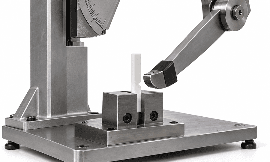
An Izod tester holds a bar in a vertical cantilever arrangement. A pendulum released from a controlled starting position strikes the exposed portion of the specimen. The machine measures the loss of pendulum energy during the impact. That reading must be adjusted using the corrections applicable to the apparatus and method before it becomes the energy used in the calculation.
2.1. Pendulum, Clamping, and Impact Position
The clamp must hold the specimen firmly without introducing avoidable movement or damage. Striker geometry, alignment, strike height, pendulum capacity, and impact speed are controlled variables. ASTM D256-26 describes a nominal impact speed near 3.5 m/s for its conventional configuration. A higher-capacity pendulum is not automatically more accurate. The absorbed energy must occupy a suitable portion of the instrument’s measuring range.
Before testing, verify the notch direction against the applicable method drawing. A reversed notch, an incorrect clamp position, or a shifted striker changes the loading condition. Such results must not be reported as ordinary notched Izod data.
2.2. Fracture Classification Matters
The recorded outcome includes what happened to the bar, not just a number. ASTM D256 distinguishes complete, hinge, partial, and non-break outcomes. ISO 180 also assigns fracture classifications. A specimen that bends without separating has not demonstrated the same fracture response as one that breaks completely.
Do not combine unlike break classes into a single material ranking without the method’s reporting rules. Report the number of specimens in each class and review any outlying energy readings before calculating a meaningful average.
3. Izod Impact Strength Formula and Calculation
3.1. ASTM D256: Corrected Energy per Specimen Width
For the applicable ASTM D256 notched Izod configuration: I = E_net / b, where I is impact resistance in J/m, E_net is corrected absorbed energy in J, and b is the measured specimen width at the notch in metres. Equipment corrections can include friction, windage, and other contributions required by the method. Do not assume one fixed correction value works for every instrument.
Worked calculation: a specimen with corrected absorbed energy of 1.79 J and measured width of 3.20 mm (0.00320 m) gives I = 1.79 / 0.00320 = 559.4 J/m. The 3.20 mm dimension is the width used for ASTM normalization, not the 10.16 mm remaining ligament dimension.
3.2. ISO 180: Corrected Energy per Specimen Section
For ISO 180:2023, unnotched impact strength is a_iU = W_c × 10³ / (h × b), while notched impact strength is a_iN = W_c × 10³ / (h × b_N). Here W_c is corrected absorbed energy in J and h, b, and b_N are measured in mm. The resulting unit is kJ/m². b_N is the remaining specimen width at the notch, not the same quantity as the ASTM D256 normalization width.
Calculation example only: with W_c = 0.50 J, thickness h = 4.00 mm, and measured remaining width b_N = 8.00 mm, ISO 180 notched impact strength is 0.50 × 1,000 / (4.00 × 8.00) = 15.6 kJ/m² to three significant figures. This is a mathematical example, not an experimental material-property claim.
4. ASTM D256 vs ISO 180: Test Methods and Specimens
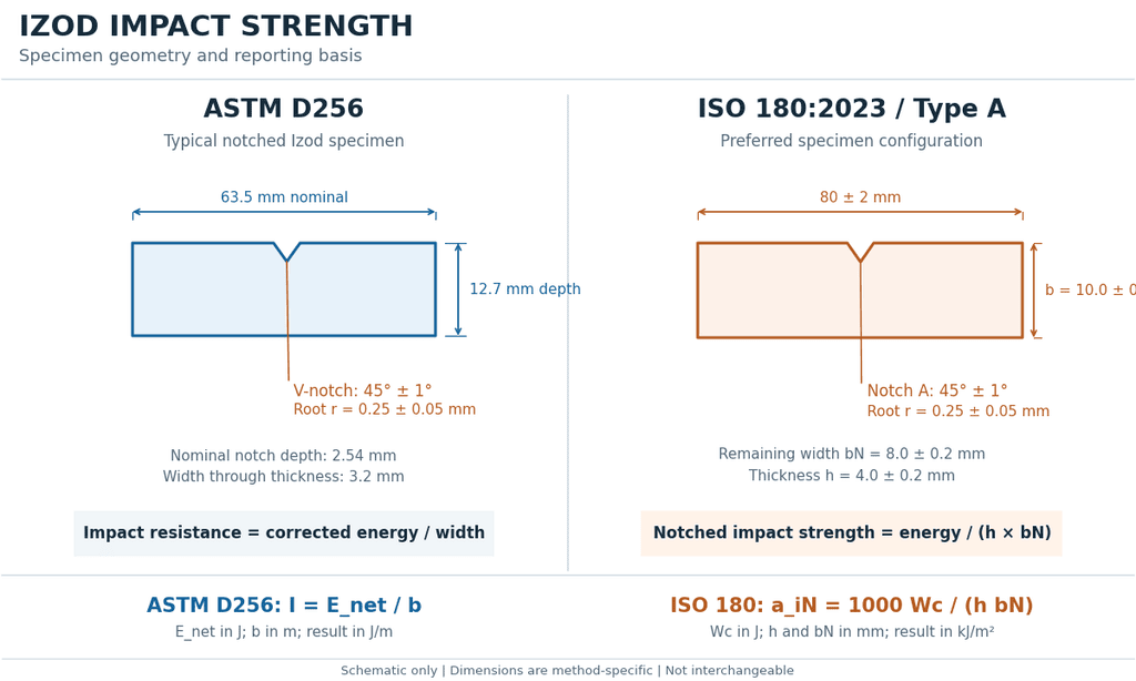
ASTM D256-26 and ISO 180:2023 both describe pendulum Izod testing of plastics, yet their reporting rules and standard specimen geometries differ. The most common comparison error is treating two reported Izod numbers as interchangeable because both involve a pendulum and a V-notch.
| Comparison item | ASTM D256-26 | ISO 180:2023 |
| Result unit | J/m, normalized by measured specimen width | kJ/m², normalized by measured specimen section |
| Common notched specimen | Approximately 63.5 mm long; dimension selections follow the standard and material specification | Preferred 80 ± 2 mm long, 10.0 ± 0.2 mm wide, 4.0 ± 0.2 mm thick |
| Notch root | 0.25 ± 0.05 mm for the conventional V-notch | Type A 0.25 ± 0.05 mm; Type B 1.00 ± 0.05 mm |
| Notch angle | 45° ± 1° for the conventional V-notch | 45° ± 1° |
| Main reporting controls | Method, notch, width, orientation, conditioning, instrument corrections, fracture class | U/A/B category, orientation, thickness, remaining notch width, conditioning, fracture class |
| Direct numerical comparison | Not appropriate without matching method and full context | Not appropriate merely by converting units |
4.1. Notch Geometry and Specimen Preparation
The notch is a controlled stress concentrator. Root radius, depth, included angle, cutter condition, and local damage can all change crack initiation. ASTM D256-26 uses a conventional notch root radius of 0.25 ± 0.05 mm and a 45° ± 1° included angle. ISO 180:2023 specifies Type A and Type B notch radii, which are not interchangeable.
Document how the notch was machined and checked. Surface melting, burrs, cutter wear, chip-out, and microcracking at the root can produce misleading differences between materials or test batches. Record actual dimensions rather than simply repeating nominal specimen dimensions.
4.2. Conditioning and Reporting
ASTM D256-26 normally refers to conditioning under ASTM D618, including 23 ± 2 °C and 50 ± 10% relative humidity for at least 40 hours unless a governing material specification states otherwise. ISO 180:2023 uses applicable ISO conditioning requirements and records the conditioning history and test temperature. Do not substitute one method’s standard conditions for the other.
A useful report identifies the grade and lot, production method, specimen orientation, notch dimensions, machine and pendulum, energy corrections, test environment, individual results, statistics, and fracture-class distribution. It must also state the standard edition and the exact test configuration.
5. What Affects Izod Impact Test Results?
Notch sensitivity is often the first variable to investigate when apparently similar plastics give different Izod values. Radius variation changes local stress concentration. Molding flow and fiber orientation change the crack path. For moisture-sensitive polymers, the conditioning history can change the balance between brittle fracture and plastic deformation.
5.1. Temperature, Moisture, and Material Identity
Compare results at the same test temperature and relevant moisture condition. A room-temperature result does not establish performance after cold storage, outdoor aging, or prolonged exposure to heat. Likewise, generic ABS, nylon, PETG, or polycarbonate labels do not define a comparable commercial formulation. Resin grade, modifiers, reinforcement, manufacturing route, and batch may matter.
5.2. Equipment Losses and Failure Modes
Check pendulum suitability and the method-specific correction procedure. Raw instrument energy includes effects that do not all represent specimen fracture. Failure categories should be reported alongside the mean and standard deviation. An average hides too much when one sample remains intact while the others fracture completely.
6. Izod Impact Testing of 3D-Printed Plastics
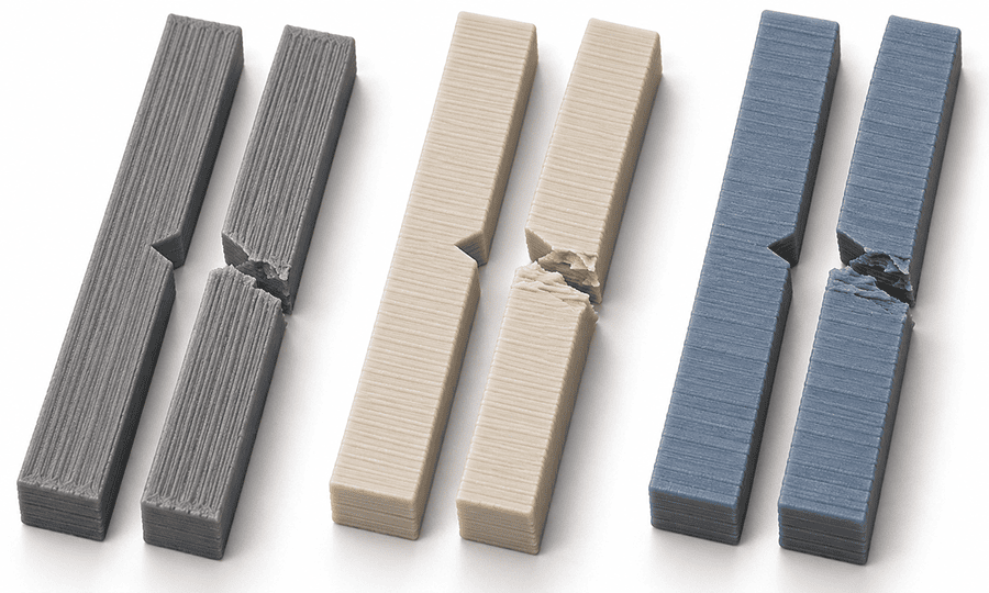
A printed Izod bar is not automatically equivalent to an injection-molded material datasheet specimen. FDM parts contain deposited roads, interlayer interfaces, and possible voids. A crack may follow an interlayer boundary instead of cutting through bulk polymer. The reported outcome therefore depends on how the bar was printed and how the notch was prepared.
6.1. Build Orientation and Notch-to-Layer Direction
Record the build axis, layer height, raster direction, perimeter count, infill construction, and notch orientation relative to layers. A notch cut across layer boundaries can initiate a different fracture path from one running along them. Print-to-size and machine-from-printed-block specimens can also differ because their skins and notch surfaces have different histories.
The published 3D printer filament types guide distinguishes base-polymer properties from printed-part validation, which is essential when specifying FDM impact coupons.
Unlike tensile stress in printed parts, Izod testing measures the response to a rapid pendulum strike; one result cannot replace the other.
6.2. What the Test Can and Cannot Validate
An Izod result on an FDM coupon can support comparisons within a controlled build and test plan. It cannot validate the drop resistance of an enclosure, snap-fit retention after impact, or the survival of a layered bracket without part-level loading evidence. Use the actual geometry, contact location, assembly restraint, and service environment when deciding whether additional tests are needed.
The additive manufacturing processes used to build the coupons determine layer interfaces and fracture paths, so identify the process and build orientation in the test record.
7. Reading Izod Data for Material Selection
Start by checking whether the two results belong to the same standard edition, test method, notch type, specimen size, conditioning, orientation, and fracture-class basis. Reject a numerical ranking when those fields are missing. A higher value from a different test configuration does not justify choosing a resin for an impact-loaded part.
Izod and Charpy testing use different support arrangements and impact geometries. Do not use a Charpy number as a direct substitute for Izod. Nor should a tensile strength or modulus figure be used to predict impact resistance without an appropriate material model and component test evidence.
When comparing grades for molded components, first establish the manufacturing assumptions in the injection molding material selection guide. Flow direction, section thickness, and notch-sensitive details may alter the resulting component behavior.
A broader material properties guide helps organize property questions, but the Izod comparison must remain tied to the measured conditions.
8. Engineering Case: Notched Izod Data for a Polycarbonate Clip Material
Image 4 | Case PC141R-261010-A, five notched specimens and fracture details; file name: lexan-141r-izod-impact-test-fracture-evidence.png; alt text: Notched Izod impact test specimens of LEXAN 141R polycarbonate showing complete breaks.
EPOC CRAFTER engineering case IZOD-PC-20261010-01 evaluates SABIC LEXAN 141R unreinforced polycarbonate for an injection-molded protective clip application. Its recorded procedure is ASTM D256-10 (2018), Method A, not ASTM D256-26. The specimens were machined from a molded panel along the melt-flow direction and conditioned for 48 hours at 23 °C and 50% relative humidity. This is a specimen-level comparison, not a finished-clip impact qualification.
The five notched specimens had nominal dimensions of 63.50 mm in length, 12.70 mm in depth, and 3.20 mm in normalization width. The record specifies a 45° V-notch, 0.25 mm root radius, and 2.54 mm notch depth. The test setup lists a 5.0 J pendulum, 3.46 m/s nominal impact velocity, and a 0.030 J correction applied to the indicated energy. The method-specific suitability of that correction depends on the documented instrument procedure.
| Specimen | Indicated energy (J) | Corrected energy (J) | Measured width (mm) | Impact result (J/m) | Break |
| IZ-01 | 1.82 | 1.79 | 3.20 | 559.4 | C |
| IZ-02 | 1.87 | 1.84 | 3.21 | 573.2 | C |
| IZ-03 | 1.78 | 1.75 | 3.19 | 548.6 | C |
| IZ-04 | 1.91 | 1.88 | 3.20 | 587.5 | C |
| IZ-05 | 1.84 | 1.81 | 3.21 | 563.9 | C |
For IZ-03, the individual normalization is 1.75 J / 0.00319 m = 548.6 J/m. Repeating the calculation for each specimen gives a five-specimen mean of 566.5 J/m and sample standard deviation of 14.7 J/m. All five specimens were classified as complete breaks (C), with reported crack initiation at the V-notch root.
The engineering case applies a comparison threshold of at least 500 J/m. All five calculated specimen values exceed that particular threshold. This statement is limited to the case Izod results and the case-specific threshold. It does not establish a universal ASTM acceptance limit or demonstrate finished snap-fit clip impact performance. The 2018-referenced procedure should not be relabeled as a D256-26 test result.
9. Specifying Izod Tests in an Engineering RFQ
A request for “impact strength” alone is not sufficient for a reliable supplier comparison. Name the standard edition and method, material grade, specimen preparation route, notch type, sample orientation, conditioning, test temperature, minimum sample count, and required fracture-code reporting. Ask the laboratory to report individual corrected energies, measured normalization dimensions, individual calculated values, mean, and dispersion.
State the project acceptance rule separately from the test method. A test standard defines how measurements are made and reported; it does not automatically set a suitable acceptance threshold for a specific enclosure, clip, or bracket. Include component-level impact requirements when the purchase decision concerns service survival, not merely material screening.
Use DFM design guidelines to inspect clip roots, sharp corners and thin sections before drawing conclusions from coupon impact data.
For rapid injection molding, review gate location and flow direction because they can change the orientation of molded specimens relative to impact loading.
Use rapid prototyping services for component-level impact trials when the actual enclosure, clip or contact geometry governs failure.
10. Engineering Questions About Izod Testing
10.1. Is a Higher Notched Izod Value Always Better?
Only when the test method, specimen geometry, conditioning, manufacturing direction, and fracture behavior are comparable. A higher number from a different setup is not proof of improved component durability.
10.2. Can ASTM D256 Results Be Converted to ISO 180 Results?
Units can be converted mathematically only after defining the normalization geometry, but numerical conversion does not make the two test methods equivalent. Report the actual method and compare like with like.
10.3. Can Izod Data Predict a 3D-Printed Part’s Drop Resistance?
Not on its own. Layer bonds, walls, infill, contact conditions, and the actual impact path affect the part’s response. Use coupon data for controlled screening and validate the product under relevant impact conditions.
10.4. What Belongs in an Izod Test Report?
At minimum, retain the standard edition and method, material and batch identity, specimen geometry and notch, processing and orientation, environmental conditions, equipment and energy correction, individual results, statistics, and fracture classes. Without these fields, comparison and procurement decisions become difficult to defend.
Ready to Quote Your CNC Prototype?
Upload your STEP file and get a DFM review + quote within 12 hours.
No tooling cost. Minimum 1 part.
