

Dewey Wu General Manager & senior mechanical engineer at EPOC CRAFTER, 15 years in design engineering, quality, and metallurgy. Hands-on across CNC machining, metalwork, sheet metal, and prototyping (subtractive + 3D printing).
1. What laser marking has to solve on an automotive CNC part
A laser mark on an automotive CNC part has to survive the finishing route, read at grade at the OEM verifier, and tie back to work order and material heat lot on demand. Three variables decide the outcome: the material and its surface state, the process step where the mark is placed (before or after anodize, ASTM A967 passivation, or plating), and the Data Matrix grade the customer reads at incoming inspection under ISO/IEC 29158.
Fiber and MOPA at 1064 nm handle bare aluminum, stainless, titanium and brass. UV at 355 nm handles anodized layers, engineering plastics, and small copper features. On automotive parts built to PPAP Level 3, the mark is a pointer to a serialized manufacturing record: if a Cognex DataMan or Keyence SR reader rejects the code at the customer’s dock, the part is nonconforming. Parameters below come from the six laser marking systems we run on CNC-machined automotive parts.
2. Fiber, MOPA, and UV: matching wavelength to the material
Fiber and MOPA at 1064 nm cover most laser marking metal work on CNC parts: aluminum, stainless, titanium, brass. UV at 355 nm handles anodized layers, engineering plastics, and small copper features. CO2 at 10.6 μm is not used on CNC parts because most bare metals reflect it too strongly for stable contrast.
Pulse width matters as much as wavelength. MOPA sources tune pulse from 2 ns into the hundreds of ns on the same machine (our JPT YDFLP-E-30-M7 covers 2 to 350 ns; Han’s G-20 covers 4 to 200 ns). Shorter pulses reduce the heat-affected zone; longer pulses at the same average power shift color toward black on stainless and titanium.
Parameters below are starting windows on our 20 to 30 W 1064 nm fiber and MOPA systems and the TRUMPF TruMark 3330 UV, verified on a shop coupon before every run.
Table 1. Starting-window parameters by material and wavelength
| 6061-T6 (baseline) | Fiber 1064 nm | 70% | 500 mm/s | 30 kHz | 1 | Mid to dark gray surface mark |
| Bare 6061 / 7075 | MOPA Fiber 1064 nm | 85% | 350 mm/s | 40 kHz | 1 | Gray-black; 7075 gives higher contrast |
| Type II anodized aluminum | Fiber 1064 nm | 30% | 1000 mm/s | 40 kHz | 1 | White-gray high contrast on dyed layer |
| Type III hard anodize | Fiber 1064 nm | 45% | 800 mm/s | 35 kHz | 1 | Even light gray to white on hard layer |
| 304 stainless | MOPA Fiber 1064 nm | 55% | 1000 mm/s | 60 kHz | 1 | Black or dark gray annealing mark |
| 316L stainless | MOPA Fiber 1064 nm | 60% | 800 mm/s | 60 kHz | 1 | Dark gray to black annealing; preferred on corrosion-critical |
| Titanium Gr5 (Ti-6Al-4V) | MOPA Fiber 1064 nm | 40% | 1200 mm/s | 40 kHz | 1 | Dark gray or blue-gray oxide color |
| Brass / copper | MOPA Fiber 1064 nm | 100% | 2000 mm/s | 60 kHz | 4 | Bright on brass; copper stays difficult at 1064 nm |
| PEEK / POM | UV 355 nm | 60% | 800 mm/s | 40 kHz | 1 | Low-heat surface color change or shallow micro-etch |
Values above are the first setup point on shop-standard bar and plate. Grade and mechanical property data live on our materials and properties guide.
2.1 Bare and anodized aluminum: 6061, 7075, Type II, Type III
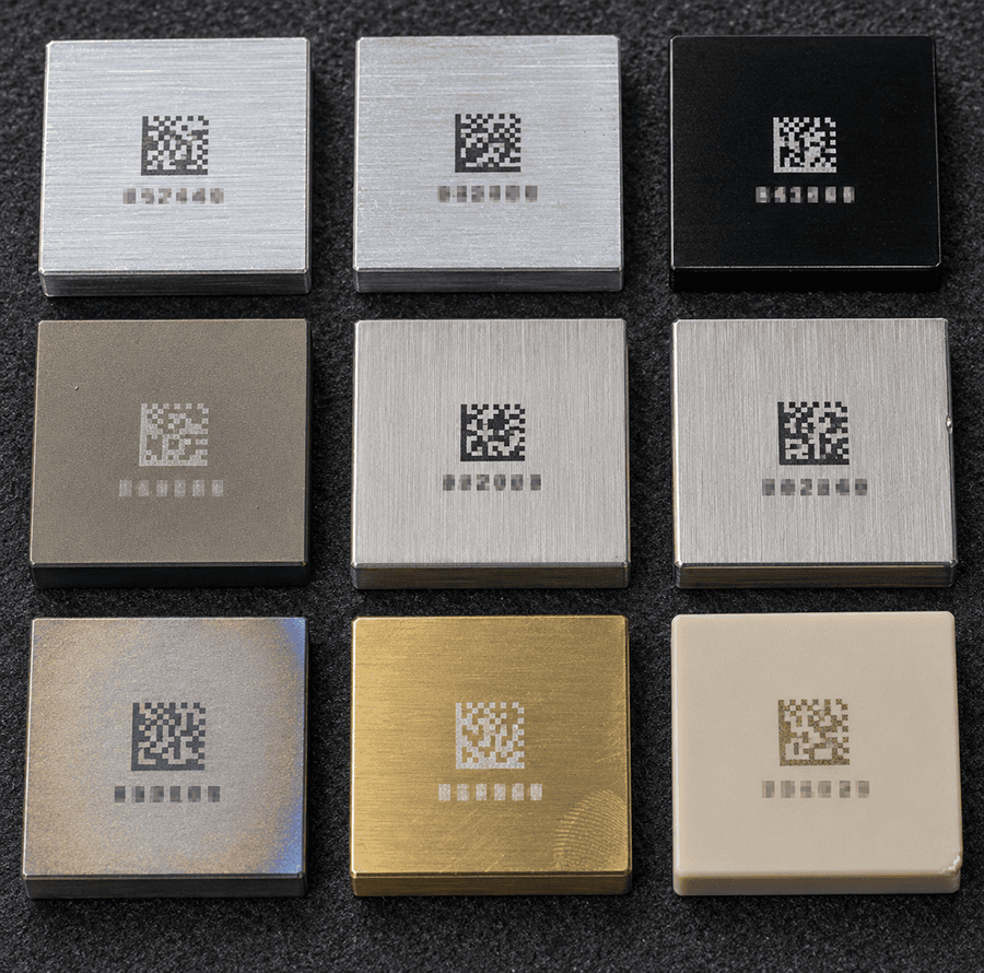
Bare 6061 and 7075 do not accept a true black mark from a standard fiber source. Absorption at 1064 nm on polished aluminum is low and the substrate conducts heat away fast. A MOPA source at longer pulse widths lands a gray-black mark a machine reader accepts; the visual stays gray under shop light. 7075 gives slightly higher contrast than 6061 because zinc shifts the mark-site oxide chemistry.
Type II anodize is the easy case. The dyed or clear porous layer absorbs 1064 nm well; low power at high speed lifts a white-gray mark against the color underneath. Two mistakes recur: too much power burns through to bare aluminum and shows silver spots inside dark modules (fails on module irregularity); too little power leaves the mark faint and drops below grade B.
Type III hard anodize needs more energy on the harder oxide. 45% / 800 mm/s / 35 kHz gives even light gray on natural Type III (25 to 75 μm). On dyed black Type III the same parameters lift a white-gray that reads under a 45° reader. Do not chase black contrast on Type III: the mark changes the oxide color, it does not remove it.
2.2 304 and 316L stainless steel
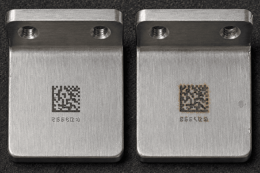
304 and 316L accept a black or dark gray annealing-type mark at 1064 nm. Annealing means the laser grows a controlled oxide film without removing material. The mark is nearly flush with the surface, which matters on corrosion-critical parts where an engraved trench gives chloride ions a place to concentrate.
316L is the corrosion-critical case: sealing faces, coolant-side surfaces, any feature that runs in a chloride environment. The mark stays annealing-type, depth stays under 10 μm, and the part goes through ASTM A967 passivation after marking to rebuild the chromium-oxide layer the local heat disturbed.
Push power beyond the annealing window and 316L shifts to material removal. That reads black on a machine vision system but leaves a valley where the passive film is thinnest. On a bearing face or coolant port, a deep marked valley is a corrosion initiation site, not an identification feature.
2.3 Titanium Gr5 and engineering plastics: PEEK, POM
Titanium Gr5 (Ti-6Al-4V) marks by growing a thin oxide film whose color depends on film thickness. Blue, purple, gold, straw, and dark gray sit on the Ti oxide interference chart, each in a narrow temperature range. Our starting point at 40% / 1200 mm/s / 40 kHz lands in the dark gray to blue-gray band. Too little power leaves a pale mark; too much power drives past the color range into a rough black burn. The mark is a color, not a burn.
Engineering plastics move to UV 355 nm. PEEK and POM absorb strongly at 355 nm and produce a controlled surface color change or shallow micro-etch without melting the resin around the mark. Fiber 1064 nm on POM burns the resin to yellow-brown; on glass-fiber PEEK it damages the reinforcement.
2.4 Brass and copper on 1064 nm vs 355 nm
Brass gives a bright white to light gray mark on MOPA at 1064 nm when energy is stacked across multiple passes. Our starting point at 100% / 2000 mm/s / 60 kHz / 4 passes lands the contrast. Fewer passes leave the mark faint; slower speed at fewer passes blackens the zinc-rich film unpredictably.
Copper is the hard case at 1064 nm: reflectivity above 90% wastes most of the pulse energy and thermal conductivity carries the rest away. On coarse features (over 3 mm high) a MOPA source with four to six passes reaches machine-readable contrast; on smaller features and on oxygen-free copper the mark drops below grade B. UV 355 nm or 532 nm green is the right tool. On automotive copper busbars and small connectors we run the TRUMPF TruMark 3330 UV.
3. Where the mark goes in the process route
Sequence decides whether the mark reads at the customer’s dock or gets scrapped after finishing. Anodize builds a new surface over the mark; passivation strips chemistry off the surface; plating covers the mark with metal; bead blasting polishes it flat. The same before-or-after logic drives heat treatment before or after CNC machining: whichever operation moves the surface the most has to run last.
Table 2. Marking sequence by finish
| Type II anodize (5 to 25 μm) | Mark after anodize | Mark contrasts against dye layer; substrate untouched | Too much power burns through to bare aluminum |
| Type III hard anodize (25 to 75 μm) | Mark after anodize | Hard oxide gives even light-gray mark; substrate protected | Reader angle matters; validate at 45° |
| ASTM A967 passivation (304 / 316L) | Mark before passivation | Passivation rebuilds chromium-oxide layer disturbed by laser heat | Post-passivation grade check to confirm readability |
| Zinc / nickel / chrome plating | Case-by-case; usually before plating | Plating covers marked-then-plated surface with metal skin | Chromate seal reduces contrast; deep marks show as raised lines |
| Bead blasting | Mark after blasting | Blast media polishes shallow marks flat and drops grade below B | On decorative parts, mark stays off blasted face |
| Powder coating (60 to 100 μm) | Mark after coating, or before with masked window | 60 to 100 μm of powder buries any substrate mark | Masking on drawing, or dedicated laser on cured powder |
Sequence sits inside broader anodizing, passivation, and plating decisions. Below are the three cases that generate the most rework on automotive CNC lines.
3.1 Mark before or after anodizing
Anodized aluminum on automotive parts almost always gets marked after the anodize. The dye layer or the natural Type III oxide is what the reader sees, and that layer only exists on the finished part. Mark first, anodize second, and the mark gets buried under 15 to 75 μm of new oxide. Contrast drops, module edges blur, and grade falls below B on the same reader that passed the pre-anodize check.
The exception: a deep engraved mark (30 to 50 μm) that has to survive stripping and re-anodizing. The trench walls disrupt the dye layer and the mark stays visible after Type II anodize. This gives up the machine-readable Data Matrix option; the mark is human-readable text only.
Dewey Wu, EPOC CRAFTER: “Anodized aluminum, if the customer wants high-contrast Data Matrix or serial numbers, we mark after the final anodize layer is done, because that is the surface they will scan at incoming inspection. If the drawing calls for a deep engraved mark that has to survive later surface treatment and stay identifiable, we consider a shallow engrave before anodize and re-verify readability after anodize.”
3.2 Mark before or after passivation (ASTM A967)
304 and 316L stainless parts get marked before ASTM A967 passivation on any part where corrosion matters. Laser annealing at 1064 nm grows an oxide film with less free chromium at the marked area. Passivation after marking dissolves free iron across the whole part and rebuilds the passive chromium-oxide layer, including on the marked area. Mark stays visible; corrosion surface stays intact.
Reverse the sequence and the laser burns off the freshly rebuilt passive layer where the mark lands. On sealing faces and coolant-side surfaces this shows up as tea staining or pitting inside 500 hours of ASTM B117 salt spray.
On parts that are not corrosion-critical, a deep engraved mark can go first, the part gets passivated, and the reader confirms grade after passivation.
Dewey Wu, EPOC CRAFTER: “For stainless where the laser will noticeably remove material, we prefer to mark first and then passivate, so the last chemical step rebuilds the corrosion-resistant surface. For pure annealing-type marks with almost no material removal, we can evaluate whether the mark can go after passivation. On plated parts, the first question is whether breaking the plating layer is allowed, not just how black the mark looks.”
3.3 Marking on plated, bead-blasted, and painted surfaces
Zinc-plated steel and chrome-plated brass sit under one rule: the plating is the corrosion barrier, and a laser mark that breaks it creates a bare-metal path to the substrate. Default is to mark before plating and let plating cover the mark. On zinc-plated automotive fasteners this is standard: contrast comes from substrate texture change, not color, and a machine reader still passes if module size and quiet zone are correct.
Some plated parts carry the mark on the plating itself. Nickel-plated trim and chrome-plated brass connector shells accept a shallow UV mark on the plated surface without breaking the corrosion barrier. Which side of the plating the mark lives on is a drawing decision inside DFM callouts for masking and finish.
Bead-blasted surfaces reject shallow marks: blast media polishes annealing-type marks flat. Mark after blasting on the same face, or place the mark on a masked-off face. Powder coating adds 60 to 100 μm over any substrate mark; either mask a window on the drawing, or mark the cured powder coat surface with a low-power UV pass.
4. Data Matrix DPM for automotive part traceability
Data Matrix is the code format automotive OEMs specify on machined parts: it packs a full serial and part number into a small footprint and reads at low contrast. QR code stays on packaging; Data Matrix carries error correction that reads through wear, oil, and partial damage. What decides whether the code passes at incoming inspection is reading it at grade B or better on the same reader the customer will use. Three variables set that: geometry (cell size, quiet zone, aperture), verification standard (ISO/IEC 29158 for DPM, ISO/IEC 15415 for 2D symbol quality), and the surface the code lives on.
Direct part marking (DPM) means the code is marked into the part instead of printed on a label. Every laser-marked Data Matrix on a machined part is a DPM code and follows the DPM verification standard.
4.1 Cell size, quiet zone, and aperture per GS1
Cell size is the width of one Data Matrix module. On a 1 mm cell code, every module is 1 mm × 1 mm. ISO/IEC 15415 uses aperture as the measurement standard; ISO/IEC 29158 sets a target aperture at 80% of cell size (a 0.5 mm cell reads with a 0.4 mm aperture).
Quiet zone is the empty margin around the code, minimum one cell width on all four sides. Any surface feature (chamfer, engraved text, scratch, machined edge) crossing into the quiet zone counts as fixed pattern damage and drops the grade one letter.
Cell size on automotive machined parts sits between 0.25 mm and 1.0 mm, with 0.5 mm as the common target. A 0.5 mm cell at 16 × 16 modules fits an 8 mm × 8 mm code footprint that lands on most bracket faces, bearing housings, and connector shells. The tolerance standards and callouts on the drawing must include the code footprint and quiet zone as protected features.
4.2 DPM verification grade per ISO/IEC 29158
ISO/IEC 29158 grades DPM codes on a letter scale A (highest) to F (fail). Automotive OEMs require grade B or better on the drawing for most serialized parts; grade C is acceptable on non-safety-critical parts and grade A on safety-critical components (airbag inflators, brake components, seatbelt pretensioners).
Verification hardware matters as much as the mark: a Cognex DataMan with 30° dome light reads a different grade on the same code than a Keyence SR-2000 with 45° direct light. The OEM drawing calls out which illumination the mark must grade under. Marking without checking against the customer’s illumination is how a shop hits grade A in-house and grade D at the customer’s dock. Every lot in our shop gets a first-article verification on a Cognex DataMan before the run continues.
4.3 Curved surfaces and reflective metals
Data Matrix on a curved surface fails when the projected code area falls outside the reader’s depth of field. The fix is not stretching the code; it is placing the code where curvature is lowest and locking focus at the geometric center. We mark curved surfaces with a rotary axis on the Trotec SpeedMarker or Z-height control on the KEYENCE MD-X1500 so the beam focus follows the surface as the part rotates. A 3 mm × 3 mm machined flat is enough to fit a 16 × 16 cell code at 0.19 mm cell.
Reflective metals fail for a different reason. On polished 316L, bare aluminum, and any surface with Ra below 0.4 μm, the reader picks up specular reflection off the modules and contrast measures inconsistent at different reader angles. What looks black to the operator reads gray to the verifier. Fix illumination and reader angle at first-article verification, and run a parameter grid on a shop coupon to find a mark that reads across angle variation.
Dewey Wu, EPOC CRAFTER: “On reflective metals, black to the eye does not mean the reader will accept it. In production we fix the illumination and the reader angle, and run a small power by speed by frequency grid on the same batch of parts. We choose parameters based on the actual Data Matrix grade, module edge quality, and distortion, not on how the mark looks.”
5. Automotive standards to specify on the drawing
Three standards do the work on machined automotive parts: IATF 16949:2016 defines the traceability chain, AIAG PPAP 4th Edition defines what documentation ships with the first submission, and ISO/IEC 29158 grades the Data Matrix at incoming inspection. AS9132 Rev A sits outside automotive but gets referenced on programs that require the tightest verification. Drawings that call out laser marking without naming the standard generate PPAP rework.
5.1 IATF 16949 traceability requirement
IATF 16949:2016 clause 8.5.2.1 requires suppliers to establish an identification and traceability plan for every automotive part. On CNC machined automotive parts, the laser-marked serial number, VIN, or Data Matrix is the physical anchor for that plan. The chain lives in MES or ERP, where the mark ID links to the work order, machine, operator, raw material heat lot, tooling, and inspection records for that specific part.
Marking without a live MES link does not meet the standard. Our shop generates every laser mark from MES at the point of marking and locks it into the system before the part leaves the fixture. The ISO 9001 and IATF 16949 quality system our records run under is the audit basis for that chain.
Dewey Wu, EPOC CRAFTER: “A serial or Data Matrix is not just engraved on the part surface. It must be tied in the MES or ERP to the work order, the material heat lot or batch, the equipment, the operating time, and the key inspection records. When the customer returns a part, scanning the code should pull the full manufacturing history.”
5.2 AIAG PPAP and the marking record
AIAG PPAP 4th Edition submissions include the marking specification as a controlled document. On PPAP Level 3, the marking record covers five items: mark content and format (serial number scheme, Data Matrix data structure, part number encoding); laser parameters used on the first article (source, wavelength, power, speed, frequency); verification method (reader model, illumination geometry, aperture); acceptance grade (grade B per ISO/IEC 29158 for most parts); and the sample verification reports for the parts included in the PPAP kit.
Missing any of these turns a PPAP submission into a revision request, and every revision cycle adds a week to program launch. Our approach is one project file from CAD to shipment, so the marking record sits with the material cert, CMM report, and FAIR in one PPAP package.
5.3 Where AS9132 Rev A is used as the DPM benchmark
AS9132 Rev A is the aerospace standard for Data Matrix quality on machined parts; it is stricter than the automotive default. It sets minimum module size at 0.19 mm on machined surfaces, requires grade B minimum, and defines verification illumination in detail. Automotive PPAP does not require AS9132 by default, and citing it on an automotive drawing without an OEM request triggers a supplier question at quote review.
AS9132 pulls into automotive on two cases: safety-critical serialized components (airbag inflators, brake components, seatbelt pretensioners, EV battery module terminals) where the OEM applies the same verification bar as aerospace, and dual-use parts shipping into both aerospace and automotive supply chains. On both cases the AS9132 reference tells the shop to run a Cognex or Keyence verifier at 30° dome light and grade every part at first article.
6. Common marking failures we catch before shipment
Most laser-marking failures on automotive CNC parts trace back to one of five patterns. Each is visible before the part ships if the shop grades the code on the customer’s reader geometry.
Low contrast on bare aluminum. A fiber source on bare 6061 or 7075 lands a gray-on-gray mark that reads at the shop but drops below grade B under 30° dome light. Fix: MOPA source at longer pulse width and a parameter grid on a coupon from the same lot. If the mark still fails, cell size is too small for the substrate reflectivity and the drawing needs a larger footprint.
Burn-through on Type II anodize. Too much power at low speed cuts through the 15 to 25 μm dye layer to bare aluminum; modules show silver spots inside dark modules and the verifier drops the grade to C or D. Fix: drop power by 10 to 15 percentage points and re-verify.
Post-passivation mark degradation. Marks placed after ASTM A967 passivation on 316L show tea staining at module edges within 500 hours of ASTM B117 salt spray. The mark reads for months but the corrosion surface fails audit. Fix: mark before passivation.
Curved-surface distortion. A Data Matrix on a shaft reads at the top of the curve but drops modules at the edges as the code wraps beyond the reader depth of field. Fix: rotary-axis marking with Z-height control, or move the code to a machined flat where curvature is under 5°.
Wrong reader assumption. The shop verifies at 45° direct light; the customer verifies at 30° dome light. Same code, different grade. Fix: ask the customer’s SQE which reader model and illumination they use, and match that geometry at first article.
On CNC machining for EV motor housings and battery enclosures, these five cover most incoming inspection rejections. Catching them in-shop keeps the part off the OEM containment sort and out of the deviation request cycle.
7. Frequently asked questions
Can Data Matrix codes survive anodizing?
A shallow Data Matrix marked on bare aluminum before anodize does not survive Type II or Type III anodize as a machine-readable code. The oxide grows into and over the mark, contrast drops, and grade falls below B. A deep engraved mark (30 to 50 μm) survives visually but loses machine readability. On anodized aluminum, mark after the final anodize.
Which laser type do you use to get black marks on stainless steel?
MOPA fiber at 1064 nm with pulse width in the 60 to 200 ns range gives controlled black annealing marks on 304 and 316L without material removal. Standard Q-switched fiber sources land dark gray at best because pulse width is fixed. Starting parameters: 55 to 60 percent power, 800 to 1000 mm/s, 60 kHz, single pass.
Should the mark go before or after passivation on 316L?
For 316L on corrosion-critical surfaces (sealing faces, coolant-side surfaces, chloride environments), mark before ASTM A967 passivation. Passivation after marking rebuilds the chromium-oxide layer the laser disturbed. Reverse sequence gives a mark that reads fine but shows tea staining at module edges under salt-spray testing. On non-corrosion-critical parts, marking after passivation is a valid trade-off.
What DPM verification grade does automotive require?
Grade B or better per ISO/IEC 29158 is the automotive default on serialized machined parts. Grade A is required on safety-critical serialized components (airbag inflators, brake system parts, seatbelt pretensioners). Grade C is accepted on non-safety-critical parts where the code function is inventory tracking, not field traceability. The drawing must name the target grade and the illumination geometry.
How does laser marking affect corrosion resistance on machined parts?
Laser marking that removes material (deep engrave, high-power marks on stainless) creates a valley in the passive surface where chloride ions concentrate and corrosion initiates at module edges. Annealing marks that grow only a controlled oxide film have minimal impact on corrosion resistance when the part gets passivated after marking. On aluminum, marks on the anodize layer sit above the substrate.
Ready to Quote Your CNC Prototype?
Upload your STEP file and get a DFM review + quote within 12 hours.
No tooling cost. Minimum 1 part.
