

Dewey Wu General Manager & senior mechanical engineer at EPOC CRAFTER, 15 years in design engineering, quality, and metallurgy. Hands-on across CNC machining, metalwork, sheet metal, and prototyping (subtractive + 3D printing).
A heat sink is a thermal component that moves heat away from a device, spreads it through a base and fins, and releases it to air or another cooling medium. A useful heat sink design starts with the allowable temperature rise and thermal resistance, then works backward through the interface, base geometry, heat sink fin design, airflow, material, and manufacturing route. Thermal conductivity alone cannot predict heat sink performance. A 6063 aluminum heat sink, copper heat sink, or CNC machined heat sink can all work well when the geometry and operating condition fit the job. This guide focuses on the decisions that matter to engineers and buyers: how a heat sink works, how to size it, when extrusion, CNC machining, skiving, or bonded fins make sense, how anodizing changes the specification, and when passive cooling should give way to active cooling or liquid cooling. This is a thermal management and heat dissipation problem as much as a part-design problem, and it applies across electronics cooling and industrial electronic cooling applications.
1. What Is a Heat Sink and How Does a Heat Sink Work?
What does a heat sink do? It creates a controlled path from the heat source to a larger heat transfer surface. Heat first conducts from the device into the thermal interface material and base, spreads through the heat sink geometry, then leaves through convection and radiation. In a heat sink with fan airflow, convection usually dominates the external path. In a passive heat sink, natural convection and radiation matter more. The exact split depends on surface temperature, orientation, enclosure conditions, and the heat transfer coefficient. How do heat sinks work in practice? The same path applies whether the part is a passive finned heat sink or an active assembly with forced air.
The key point is that a heatsink is not a material property. Junction to ambient thermal resistance, thermal interface resistance, base spreading, fin efficiency, heat sink surface area, and heat sink airflow all sit in the same path. Two heat sinks made from the same alloy can reach different heat sink temperatures because their source footprint, mounting pressure, fin spacing, airflow, or base thickness differs.
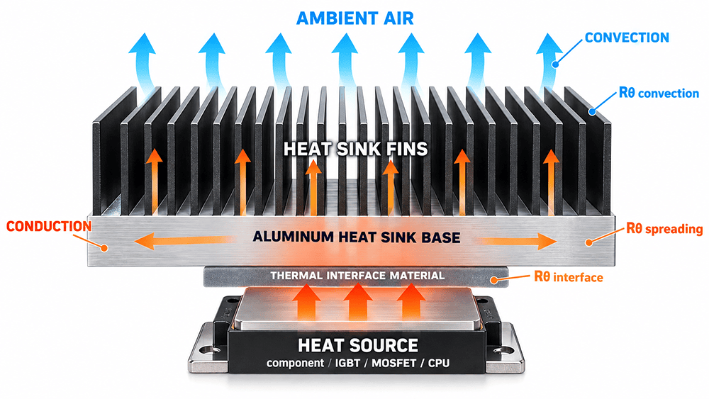
EPOC CRAFTER shop-floor data makes that distinction concrete. A 6063-T5 industrial heat sink for a 180 W IGBT controller was tested at 35°C ambient with 2.5 m/s channel airflow. The project reported 0.17°C/W base to ambient resistance after the base was finish milled, the contact face was masked during anodizing, and fin height was revised from 27 to 29 mm. The same alloy was used before and after. The measured improvement came from the complete configuration, not from a change in bulk thermal conductivity.
2. Heat Sink Design Starts With the Thermal Resistance Budget
Heat sink sizing should start with power, maximum allowable device temperature, worst case ambient temperature, and the thermal resistance already consumed by the semiconductor package and interface. The first order thermal resistance calculation is Rθ = ΔT / Q. The reference temperatures must be stated. Heat sink thermal resistance measured from base to ambient is not the same quantity as junction to ambient thermal resistance.
For the EPOC CRAFTER case, the base reached 65.6°C at 180 W with 35.0°C ambient. Using those two measurement points gives (65.6 – 35.0) / 180 = 0.17°C/W. The heat source or case temperature was 76.8°C, so using that point would produce a different number. A heat sink design calculation is only useful when the temperature nodes, heat input, airflow, TIM material, and mounting condition are defined. This heat dissipation calculation is valid only for the stated base and ambient measurement points.
The same case used a 0.25 mm silicone thermal pad rated at 6.0 W/mK and four M4 mounting screws at 4.0 N·m each. These details matter because thermal interface resistance changes with bond line thickness, contact quality, flatness, and clamping. The original base flatness was 0.13 mm with Ra 3.1 µm. After finish machining, the measured values were 0.035 mm flatness and Ra 1.1 µm. Fin height also changed, so the 0.07°C/W improvement cannot be assigned to the interface alone.
A thermal resistance calculator or heat sink design calculator can help with first order budgeting, but it cannot replace the operating condition. Use the calculator to frame the problem, then validate the assembled heat sink under the same power, ambient, interface, and airflow condition that defines acceptance.
3. Heat Sink Materials and the Role of Thermal Conductivity
Heat sink material selection affects conduction, heat spreading, mass, stiffness, machining, extrusion, joining, and surface treatment. Aluminum heat sink material is often selected because aluminum combines useful conductivity with low density and mature extrusion and CNC routes. Copper heat sink designs provide higher bulk conductivity and can help where local spreading is the bottleneck, but the weight, machining behavior, and cost structure are different. In UK specifications, the same component may be described as an aluminium heat sink.
There is no single best material for heat sink design without a defined constraint. The practical aluminum vs copper heat sink decision is whether higher conductivity solves a real spreading or package problem. A large extruded aluminum heat sink can outperform a compact copper design when airflow and usable fin area dominate. A copper base can be valuable when a small hotspot makes spreading resistance dominant. A copper vs aluminum heat sink comparison should therefore start with the dominant thermal constraint, not a single conductivity value. Compare the thermal conductivity of aluminum and the thermal conductivity of copper only after the alloy, temper, temperature, and data source are known.
For alloy-level selection, the published aluminum heat sink material selection guide covers 6061 vs 6063 heat sink choices, 6063 aluminum heat sink profiles, 6061 heat sink bases, 1050, and the boundary between typical thermal conductivity data and material specification requirements. That avoids repeating a full alloy table here.
ASTM B221/B221M-21 applies to aluminum and aluminum-alloy extruded profiles, including the 6063-T5 raw form used in the case. The standard covers product form, chemistry, and mechanical requirements. It does not certify heat sink thermal resistance, heat sink efficiency, fin spacing, pressure drop, or finished CNC geometry. ASTM E1461-13(2022) measures thermal diffusivity by the flash method. It does not test complete heat sink performance or anodized aluminum thermal conductivity as an assembled system property.
The broader heat sink material properties reference is useful when strength, density, and process compatibility need to be compared outside the heat sink context.
4. Heat Sink Fin Design, Airflow, and Pressure Drop
Heat sink fin design is a coupled thermal and manufacturing problem. Heat sink fin thickness, heat sink fin spacing, heat sink fin height, fin efficiency, base thickness, and channel airflow must be evaluated together. More fins increase nominal heat sink surface area, but narrow channels can raise heat sink pressure drop and reduce the air that actually passes through the fin field. Taller fins add area, but the added material is less useful when conduction to the tip is weak or the airflow cannot reach the surface effectively.
The case part used 24 straight fins on a 120 × 80 mm base, with 29.0 mm fin height, 1.20 mm fin thickness, 2.20 mm channel width, and 3.40 mm pitch. The measured channel velocity was 2.5 m/s and pressure drop was 42 Pa. Those are project values, not generic heat sink optimization rules. A pin fin heat sink, plate fin heat sink, or straight fin heat sink can require a different balance because the flow path and available surface area change.
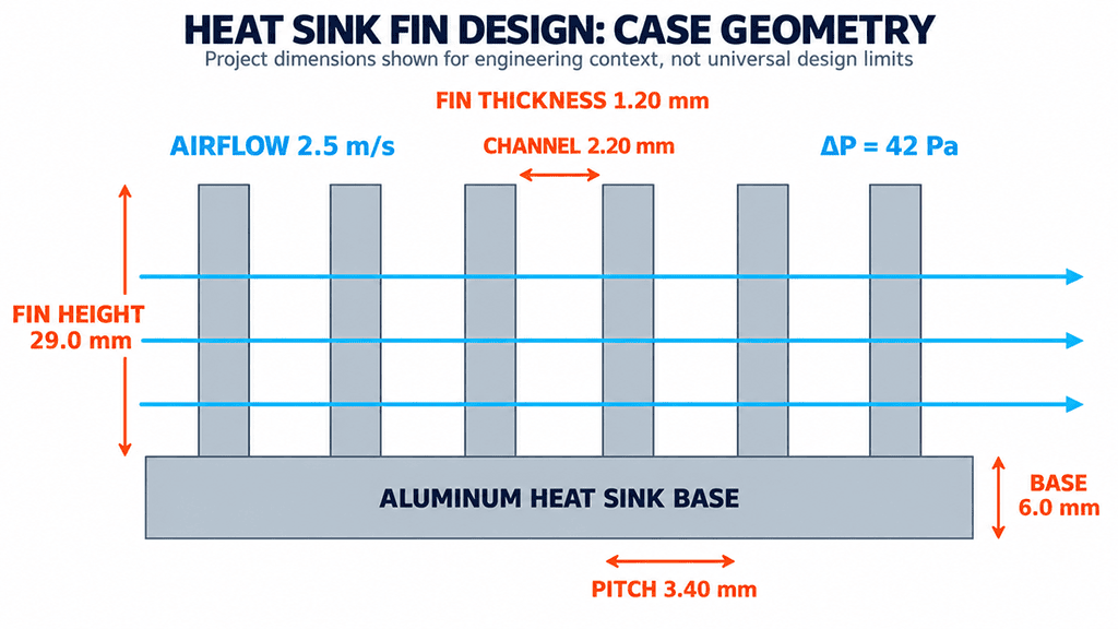
Heat sink airflow also depends on the enclosure. Fan free-air CFM is not the same as channel flow. Filters, grills, cable bundles, inlet restrictions, outlet restrictions, and bypass paths move the operating point. A heat sink with fan cooling should therefore be evaluated with the fan curve or measured channel condition, not only the fan label.
Before release, check the fin field against the intended process. The case required a fin support comb during the second machining setup. That fixture detail is easy to miss in a thermal model, but it protects the fin array while the base and mounting features are machined. The heat sink DFM guidelines provide the broader manufacturing context for tool access, thin features, fixture support, and inspection planning.
5. Heat Sink Types and Manufacturing Routes
Heat sink manufacturing should follow the dominant geometry. Extrusion suits a repeated constant cross section. Heat sink machining adds local pockets, holes, threads, datum faces, and nonuniform features. A skived heat sink can create dense thin fins from stock. A bonded fin heat sink or folded fin heat sink separates the fin array from the base. A die cast heat sink can integrate fins, bosses, ribs, and housing features when tooling and volume support the route. Stamped heat sink designs are useful for thin sheet based parts where the thermal load and geometry fit the process. The main types of heat sinks differ as much by heat sink fabrication route as by fin shape.
| Process | Good fit | Main constraint | Use it when |
| Extruded heat sink | Constant cross section, repeated straight fins | Die and profile manufacturability | The fin field repeats and volume justifies a dedicated profile |
| CNC machined heat sink | Local geometry, mounting features, controlled base faces | Tool access, fin deflection, cycle time | Low volume or nonuniform geometry needs machining freedom |
| Skived fin heat sink | Dense thin fin arrays | Skiving direction and fin stability | Fin density is difficult for extrusion |
| Bonded or folded fins | Large or separately optimized fin arrays | Joint quality and interface control | Separate base and fin manufacture adds useful freedom |
| Die cast heat sink | Integrated housing, ribs, bosses, fins | Tooling, draft, casting quality | The thermal part also carries structural features |
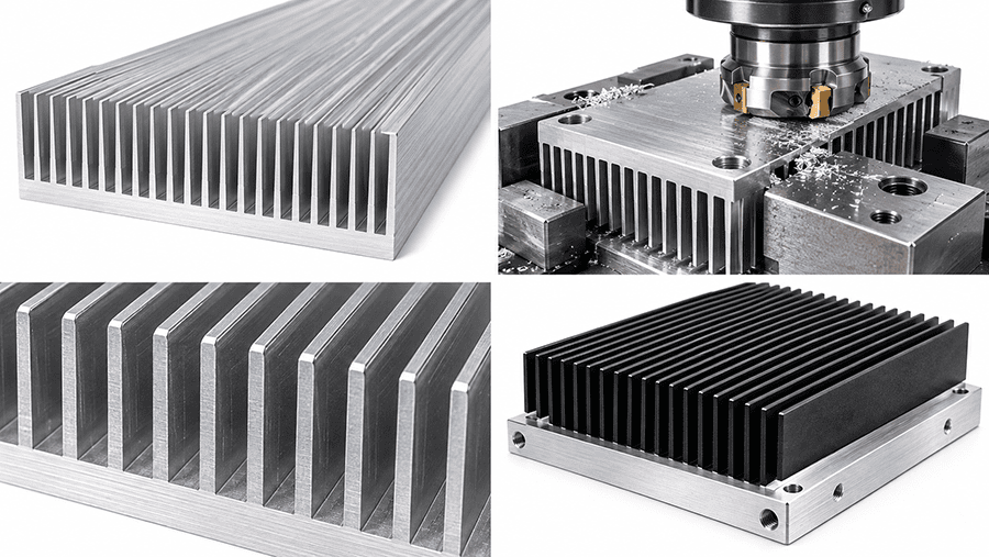
The EPOC CRAFTER case used an aluminum extrusion heat sink route with secondary CNC machining. Extrusion created the 24-fin section efficiently at 500 pieces. CNC face milling restored the functional contact face, while drilling, tapping, and contouring created the mounting features. Two setups were used. The final heat transfer base measured 0.035 mm flatness against a ≤0.05 mm drawing requirement and Ra 1.1 µm against Ra ≤1.6 µm.
That hybrid route is often more useful than an artificial extruded vs machined heat sink choice. Use extrusion for geometry that repeats. Use CNC machining where machining changes a functional requirement. A monolithic CNC heat sink can still be appropriate when quantity is low, geometry changes across the part, or extrusion tooling would lock the design too early. The CNC heat sink machining capability page covers the machining route for controlled contact faces, holes, threads, and custom aluminum heat sink features. The same logic applies to a finned heat sink that combines a repeated profile with local machined features.
For a custom heatsink or custom heat sink, quantity still affects the process decision. Do not use a fixed universal breakeven. Geometry, tooling, material, surface finish, inspection, and recurring demand move the economics. EPOC CRAFTER shop-floor data for this 500-piece industrial heat sink supports extrusion plus CNC for this specific design. It does not establish a universal 500-piece rule. The low-volume custom heat sink production page provides the wider process selection context for repeat builds and tooling decisions.
6. Anodized Aluminum Heat Sinks and Surface Requirements
Aluminum anodizing should be specified by surface function, not by color alone. ISO 7599:2018 covers decorative and protective anodic oxidation coatings on aluminum and remains current after ISO review in 2023. It supports coating classes, significant surfaces, pretreatment, appearance, sealing, and inspection. It does not specify heat sink thermal resistance, CNC dimensional compensation, or extrusion geometry.
| ISO 7599 class | Minimum average thickness | Minimum local thickness | Decision meaning |
| AA5 | 5 µm | 4 µm | Thin decorative or protective class when the specified service condition supports it |
| AA10 | 10 µm | 8 µm | Higher coating requirement where the project calls for more protection |
| AA15 | 15 µm | 12 µm | Use only when the finish specification requires this class |
| AA20 | 20 µm | 16 µm | Thicker protective class, not a universal heat sink default |
| AA25 | 25 µm | 20 µm | High decorative or protective thickness class, not hard anodizing by definition |
The minimum local thickness is 80 percent of the minimum average thickness for these classes. ISO 7599 also separates decorative and protective anodizing from hard anodic oxidation used mainly for engineering wear resistance. The standard does not support a claim that every black anodized heat sink should use AA20 or AA25.
The case used a different project specification, MIL-PRF-8625 Type II, Class 2, with 12 to 18 µm black sulfuric anodizing. The heat transfer base contact face and threaded holes were masked. Final coating measurements were 14.6 to 16.2 µm. The drawing also controlled significant surfaces and contact mark location. That separation matters because an anodized heat sink can pass appearance inspection and still fail assembly or thermal requirements if functional surfaces are not controlled.
Does anodizing affect heat transfer? It can change surface radiation and it changes the physical condition of coated interfaces, but black color alone does not certify better cooling. A black anodized aluminum surface should be treated as a finish specification unless a thermal test demonstrates an assembly benefit under the relevant condition. Why are heat sinks black? Often for appearance, protection, and surface emissivity, but the thermal significance depends on whether radiation is important compared with convection and interface resistance.
The heat sink surface finishing capability page covers masking and coating planning. Where tight fits or threads are involved, the 6061 heat sink pre-anodize machining article shows why machining allowance, masking, surface preparation, and post-finish inspection must be considered as one chain.
7. Passive vs Active Cooling and When to Escalate
Passive cooling uses natural convection and radiation without a fan or pump. An active heat sink adds forced airflow, while a passive cooling system depends more strongly on orientation, spacing, enclosure temperature, and available natural convection. The passive vs active cooling decision should be based on the required thermal resistance and the product constraints, not on a wattage threshold. The same selection logic applies to a CPU heatsink, CPU heat sink, GPU heat sink, LED heatsink, and LED heat sink when the packaging and airflow are defined.
When air cooling is still viable, a heat pipe heat sink can move heat from a concentrated source to a larger fin area, and vapor chamber cooling can spread heat across a planar base. Heat pipe cooling and a vapor chamber heat sink change how heat reaches the fins.
| Architecture | Main job | When it becomes useful | New constraint |
| Passive heat sink | Reject heat without a fan | Natural convection can meet the target within the available envelope | Orientation, fin spacing, ambient conditions |
| Active heat sink | Increase convection with a fan | Forced airflow provides the required heat transfer coefficient | Fan curve, noise, reliability, pressure drop |
| Heat pipe heat sink | Move heat to a remote or larger fin field | Source location limits direct spreading | Routing, attachment, orientation sensitivity by design |
| Vapor chamber heat sink | Spread a concentrated hotspot across a base | Solid-base spreading becomes limiting | Package thickness, sealing, integration |
| Cold plate cooling | Transfer heat into a liquid loop | Airflow or package limits prevent air cooling from meeting the target | Pump, coolant, sealing, pressure drop, leak validation |
Heat sink vs heat pipe is therefore not a strict either-or choice. The two can be combined. Heat sink vs liquid cooling is a larger architecture decision because a cold plate adds a hydraulic system. The EPOC CRAFTER 180 W case stayed with forced air because the final heat sink met 0.17°C/W against a ≤0.20°C/W requirement under the defined test condition. Power alone would not have justified liquid cooling.
When liquid cooling is genuinely required, EPOC CRAFTER has a published liquid cooling manufacturing case that shows how channel geometry, FSW sealing, flatness, leak testing, and inspection become new design variables. That is a different problem from a conventional electronic heat sink, CPU heat sink, GPU heat sink, LED heat sink, amplifier heat sink, or industrial heat sink.
8. Custom Heat Sink Specifications and RFQ Checklist
A heat sink manufacturer or heat sink supplier can quote the geometry shown in CAD, but a useful RFQ must also state the thermal condition and the CTQs. This is especially important for an IGBT heat sink, MOSFET heat sink, PCB heat sink, or other power electronics heat sink where mounting, source footprint, and interface quality can dominate the result. An aluminum heat sink manufacturer should be able to separate raw material compliance from finished-part CTQs and thermal validation. In practice, how to choose a heat sink starts with the required thermal result, then narrows the material, airflow, geometry, process, and inspection path.
| RFQ item | What to state | Why it changes the decision |
| Thermal load | Dissipated power and maximum device or case temperature | Sets the allowable temperature rise |
| Ambient and cooling | Ambient temperature, passive or forced cooling, airflow direction, fan or channel condition | Defines the external thermal boundary |
| Source and interface | Heat source footprint, TIM, bond line, clamping or torque | Controls spreading and thermal interface resistance |
| Geometry | Envelope, fixed features, adjustable fin geometry | Separates packaging constraints from supplier optimization |
| Material and route | Alloy, temper, product form, locked or supplier-proposed process | Connects the design to extrusion, heat sink machining, skiving, or casting |
| Functional surfaces | Flatness, parallelism, Ra, coating or masking condition | Makes the thermal contact surface measurable |
| Mounting features | Holes, threads, datums, position requirements | Protects assembly and repeatability |
| Finish | Coating specification, significant surfaces, masking, sealing, appearance | Prevents cosmetic notes from conflicting with functional surfaces |
| Validation | Heat input, sensor locations, steady state criterion, acceptance resistance | Makes thermal results reproducible |
| Quantity | Prototype, low volume, or recurring production quantity | Changes tooling and manufacturing economics |
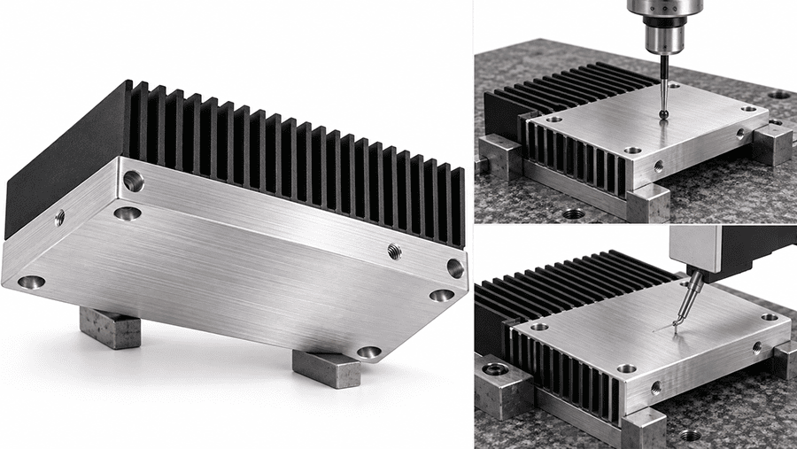
The EPOC CRAFTER case demonstrates what good heat sink specifications look like. The drawing controlled ≤0.05 mm base flatness, Ra ≤1.6 µm, fin thickness 1.20 ±0.10 mm, fin spacing 2.20 ±0.15 mm, pitch 3.40 ±0.15 mm, and mounting hole position. Inspection matched each CTQ to a method: CMM for flatness and position, profilometer for Ra, blade micrometer for fin thickness, optical comparator for fin spacing and pitch, and GO/NO-GO gauges for M3 × 0.5-6H threads.
The heat sink GD&T standards resource is the right next step when a custom heat sink manufacturer must quote datum structure, geometric controls, or inspection requirements. A strong heat sink selection or heat sink sizing package fixes the thermal and mechanical CTQs but leaves manufacturing freedom where the supplier can improve cost or process robustness.
9. Real Questions Engineers Ask
9.1 How to calculate heat sink size?
Start with dissipated power, the maximum allowed junction or case temperature, worst case ambient temperature, package resistance, and interface resistance. The remaining thermal budget sets the required sink to ambient resistance. Heat sink size follows from that target plus the available airflow and geometry. There is no universal watts-to-volume conversion. This is also the practical answer to how to size a heat sink when no validated catalog curve already matches the application.
9.2 How do I calculate heat sink thermal resistance?
Use the temperature difference between two explicitly defined nodes divided by heat flow. For a heat sink base to ambient measurement, Rθ = (Tbase – Tambient) / Q. Do not mix that result with junction to ambient or junction to case values from a component datasheet unless the reference nodes are compatible.
9.3 Should a low-volume custom heatsink be CNC machined, skived, or extruded?
Use geometry first, then quantity. A constant cross section points toward extrusion. Nonuniform mounting features and very low quantities favor CNC machining. Dense thin fins can favor skiving. A hybrid route is common when an extrusion creates the fin field and CNC machining finishes the base and mounting features.
9.4 Does anodizing affect heat transfer?
Yes, but the effect depends on where the coating sits and which heat-transfer mode matters. The contact surface, oxide layer, radiation, convection, and assembly interface should be separated. Do not assume black anodizing automatically lowers total thermal resistance.
9.5 What are heat sinks made of, and why are heat sinks made of aluminum?
Aluminum is common because it balances conductivity, density, extrusion, machining, and finishing. Copper is used when higher conductivity solves a specific spreading problem. Composite structures, heat pipes, vapor chambers, and bonded fins can combine materials when one material cannot satisfy every constraint.
9.6 How do I know whether a heat sink is actually working well?
Compare measured device or base temperature against the design limit under the worst credible ambient and airflow condition. Record power, sensor location, orientation, and steady state. One bench temperature without those conditions cannot establish heat sink performance.
10. Final Design Check
A custom heat sink is ready for release when the thermal requirement, material, heat sink geometry, airflow, manufacturing route, interface, surface finish, and inspection plan describe the same operating condition. The EPOC CRAFTER case met its target through a specific chain: 6063-T5 extrusion for the repeated fin field, two CNC setups for the contact base and mounting features, masked Type II black anodizing, and final dimensional and thermal validation. The final result was 0.17°C/W base to ambient at 180 W, 35°C ambient, and 2.5 m/s channel airflow.
Use that case as evidence of the decision process, not as a template for another design. For a new custom heat sink, send the STEP model and drawing with power, maximum device temperature, ambient condition, source footprint, airflow condition, TIM, quantity, finish, and acceptance method. That gives the supplier enough information to choose the right heat sink manufacturing route without guessing which thermal constraint matters most.
Ready to Quote Your CNC Prototype?
Upload your STEP file and get a DFM review + quote within 12 hours.
No tooling cost. Minimum 1 part.
