

Dewey Wu General Manager & senior mechanical engineer at EPOC CRAFTER, 15 years in design engineering, quality, and metallurgy. Hands-on across CNC machining, metalwork, sheet metal, and prototyping (subtractive + 3D printing).
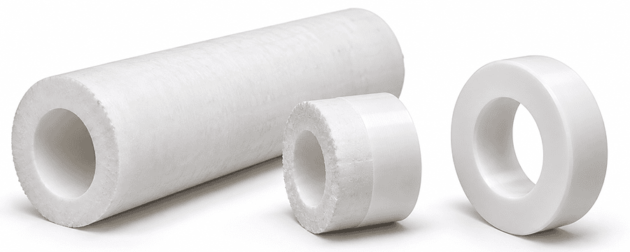
PTFE, or polytetrafluoroethylene, is the fluoropolymer commonly associated with the Teflon trade name. PTFE machining is usually straightforward at the cutting edge, but dimensional control is not. Low stiffness, low friction, PTFE thermal expansion, clamping deformation and time dependent recovery can change a bore, OD or flatness after the part leaves the fixture. ISO 13000-1:2021 covers processed unfilled PTFE semi-finished stock, while ISO 899-1:2017 defines tensile creep testing for plastics. Neither standard supplies a universal PTFE machining tolerance. For critical machined PTFE parts, the drawing needs to define the functional CTQs and, when necessary, the inspection temperature, free-state condition and delay after machining.
1. What Is Teflon (PTFE), and Which Properties Matter in Machining?
If the search question is “what is PTFE?”, the short answer is that PTFE is a fluoropolymer plastic, polytetrafluoroethylene. PTFE vs Teflon is mainly a naming distinction: PTFE is the polymer name, while Teflon is a Chemours trademark used for fluoropolymer products. On a drawing or purchase order, the material specification should identify the PTFE material and grade rather than rely on the trade name alone.
PTFE properties that matter in CNC work are not just strength values. PTFE material properties such as low friction, low stiffness, thermal expansion and creep can make a soft PTFE plastic part harder to hold and inspect repeatably. The question “is PTFE a plastic?” has a simple answer: yes, it is a fluoropolymer plastic. A PTFE coefficient of thermal expansion should come from the selected grade data when temperature-driven size change matters. PTFE mechanical properties also depend on resin, stock route and test condition, so tensile strength or PTFE hardness data should not be treated as a finished-part tolerance.
| Property / condition | Verified value or statement | Source basis | Engineering meaning |
| PTFE density | 2.13 to 2.19 g/cm³ for normal unfilled semi-finished products | ISO 13000-1:2021 | Useful for stock verification, not a machining tolerance. |
| PTFE hardness | Ball indentation hardness >23 MPa or Shore D >54 where the product permits reliable measurement | ISO 13000-1:2021 | A semi-finished product requirement, not a thread or insert strength value. |
| Type S dimensional stability | Dimensional change ≤0.5% under the prescribed ISO 13000-2 test | ISO 13000-1:2021 / ISO 13000-2:2021 | Does not guarantee a finished CNC tolerance. |
| PTFE melting point reference | Teflon PTFE 7A X second melting peak: 327 ±10 °C, typical | Chemours Teflon PTFE 7A X data sheet | Grade-specific typical data. It is not the PTFE service temperature or a machining limit. |
| Low friction behavior | Chemours identifies high lubricity / low coefficient of friction as a PTFE property | Chemours technical material | Relevant to seals, guides and bearings, but friction performance still depends on the application. |
This is why a PTFE temperature range, PTFE coefficient of friction or PTFE tensile strength should only be quoted with the relevant grade and test basis. For the broader material specification, EPOC CRAFTER’s PTFE machining data sheet provides the resin and stock basis used for machinable PTFE.
2. Why PTFE Dimensions Move After Machining
A PTFE part can be on size while clamped and move after release. Fixture distortion, PTFE thermal expansion, elastic recovery and time dependent deformation can overlap, which is why PTFE dimensional stability cannot be judged from the machine coordinate alone.
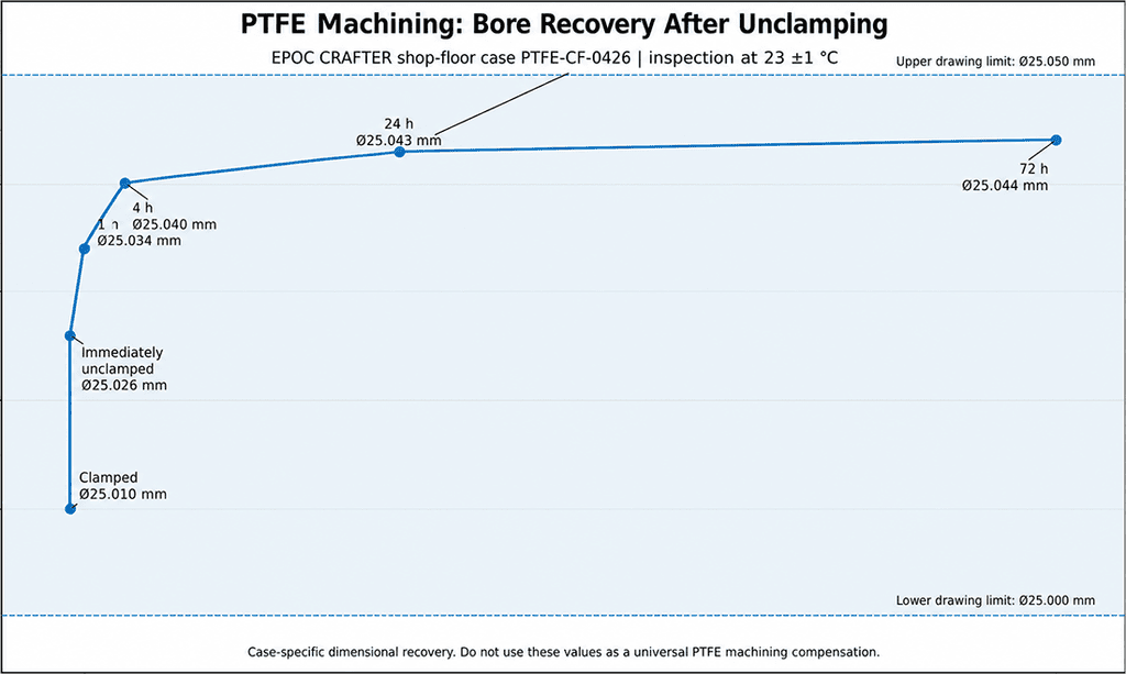
EPOC CRAFTER shop-floor case PTFE-CS-0426 used virgin PTFE from a compression-moulded tube. The finished bore was cut to 25.010 mm while clamped. It measured 25.026 mm immediately after unclamping, 25.034 mm after 1 h, 25.040 mm after 4 h and 25.043 mm after 24 h. The 24 h free-state value was 0.033 mm larger than the clamped value. The sealing-face flatness also changed from 0.061 mm immediately after release to 0.038 mm after 24 h.
Those numbers are case data, not a universal PTFE creep allowance. They show why the acceptance state must be defined when the drawing tolerance is close to the material movement.
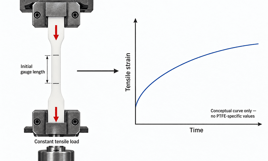
The phrase “Teflon cold flow” is often used loosely for several time-dependent deformation effects. ISO 899-1:2017 is relevant here only within its tensile-creep scope. It defines tensile creep testing under sustained tensile load and can generate tensile creep strain and creep modulus data. It does not define PTFE cold flow in compression, press-fit interference, insert retention, seal life or finished CNC tolerances.
For engineers asking how to machine Teflon accurately, the practical question is therefore not just tool motion. It is whether the free part is still within the functional tolerance at the agreed inspection time.
That distinction also applies to PTFE CNC machining capability: machine accuracy does not remove the need to control polymer deformation and inspection state.
3. Stock Specification, ISO 13000 and Finished Tolerances
ISO 13000-1:2021 applies to processed unfilled PTFE semi-finished products and recognizes forms such as PTFE sheet, PTFE rod and PTFE tube. PTFE types, PTFE grades and stock forms describe different things, so a PTFE specification should state the material basis and the product form separately. Virgin PTFE, reprocessed material and recycled resin are addressed within the standard’s unfilled PTFE scope. Filled PTFE, including glass filled PTFE, carbon filled PTFE, bronze filled PTFE and graphite filled PTFE, needs its own applicable PTFE material specification.
Stock tolerance is not finished-part tolerance. For example, ISO 13000-1 gives extruded or moulded rod at 10 mm diameter and above a +6/0% stock diameter tolerance, while centreless-ground rod can be supplied at +0.04/0 mm. These are incoming stock conditions used for allowance and purchasing. They do not authorize the same tolerance on a machined bore or sealing face.
The case part required a Ø25.000 +0.050/−0.000 mm bore, Ø50.000 ±0.050 mm OD, 0.050 mm sealing-face flatness and 0.030 mm bore roundness. Those requirements came from the part function and inspection plan.
Type S also needs a boundary. Its ≤0.5% dimensional-change requirement is measured through an ISO 13000-2 test method. The general method includes conditioning at 23 ±2 °C, heating at 285 ±5 °C and reconditioning before measurement. That is a laboratory dimensional-stability test, not a production annealing recipe and not proof that a finished part will hold ±0.05 mm.
Use CNC tolerance and GD&T standards to define the drawing framework, then add PTFE-specific inspection conditions only where material movement can change acceptance.
4. Machining Strategy, Surface Finish and Inserts
4.1 Workholding and Finish Machining
PTFE machinability is good in the sense that sharp tools can cut the polymer cleanly, but workholding can dominate the final geometry. When machining PTFE, often described in shop language as machining Teflon, the case used a soft full-wrap bored polymer collet with 30 mm circumferential contact. After bore growth became a repeatability problem, the recorded hydraulic-equivalent setting was reduced from 0.24 MPa to 0.18 MPa. A 24 h hold at 23 ±1 °C was added between roughing and finish machining.
The rough bore changed from 24.700 mm immediately after roughing to 24.742 mm before finishing. That 0.042 mm change occurred before the final sizing cut. The process then used a finish-bore target of Ø25.010 to 25.015 mm because the free-state recovery had been measured on this specific part.
That target is case-specific. Do not copy it to another PTFE geometry. Instead, control support, clamping and rough-to-finish sequence, then establish any machining offset from measured process behavior.
These choices follow the same principles outlined in the CNC DFM guidelines: support and functional geometry come before an arbitrary tighter tolerance.
4.2 PTFE Surface Finish, Burrs and Inspection
ISO 13000-1 allows purchaser and supplier to agree surface requirements for PTFE stock, but it does not give a universal PTFE surface roughness for CNC parts. In the case, the bore and sealing face were specified at Ra ≤1.6 µm and measured Ra 0.7 to 1.3 µm.
The actual defect was local: light feather burrs at cross-drilled insert holes and stringing at the bore exit. Surface roughness and edge condition are separate requirements. A part can pass Ra and still fail assembly because of a burr.
Final inspection was performed 24 h after machining at 23 ±1 °C, with the part free-standing and unclamped. The bore was air-gauged, OD and thickness used a low-force comparator, and flatness was checked on a granite plate. This inspection condition should be documented alongside the engineering drawing tolerances when a soft polymer’s measurement state affects acceptance.
4.3 PTFE Threads and Metal Inserts
PTFE threads can be suitable for light loads, but repeated fastening or sustained preload may justify PTFE inserts made from metal or another validated retention system. ISO 13000-1 and ISO 13000-2 do not specify insert interference, pull-out load or torque-out resistance, so the joint must be validated at part level.
The case used four 316L stainless M4 × 0.7 flanged inserts. The measured installation force was 1.2 to 1.6 kN, pull-out force was 820 to 960 N and torque-out resistance was 3.1 to 3.6 N·m. Post-installation local OD change was +0.008 mm maximum. These are EPOC CRAFTER shop-floor results for PTFE-CS-0426, not generic PTFE insert design values.

5. Chemical Service and PTFE Applications
PTFE chemical resistance is a strong reason to consider the material, but chemical compatibility alone does not define service life. A chemical-service part still has to retain geometry and mechanical function under its actual medium, concentration, temperature, pressure, sustained load and exposure time.
PTFE-CS-0426 was specified for up to 37 wt% hydrochloric acid, a deionized-water rinse, 10 to 80 °C service, 0.60 MPa internal pressure and a sustained 180 N axial seating load. Those conditions describe the case. They do not establish a universal PTFE acid resistance limit or lifetime.
What is Teflon used for in machined parts, and what is PTFE used for more broadly? Common PTFE uses include PTFE seals, PTFE gaskets, PTFE valve seats, PTFE bushings, PTFE bearings and PTFE electrical insulation. The functional CTQ changes with the application. A seal may be driven by flatness and contact pressure. A bushing may be driven by running clearance and wear. An insulator may be driven by geometry, cleanliness and electrical requirements.
PTFE operating temperature and PTFE service temperature should come from the selected grade and service data. A melting peak is not a service-temperature rating.
When comparing PTFE with nylon, PEEK, UHMWPE, PFA or PVDF, the engineering plastics properties guide provides a broader basis for material selection.
Nylon has a different dimensional risk because moisture absorption matters; that topic is covered separately in the nylon CNC machining material guide.
6. PTFE CNC RFQ Checklist
A PTFE RFQ should define the result the part must meet, not prescribe an unvalidated machining recipe.
| RFQ field | What to state | Decision value |
| Material | Exact PTFE grade or applicable specification; state virgin or filled PTFE | Prevents a generic ‘PTFE’ callout from hiding composition or stock-condition differences. |
| Stock form / condition | PTFE sheet, rod, tube or moulded blank; Type P or Type S when applicable | Sets incoming material and machining allowance. |
| Critical dimensions | Only functional bores, OD, thickness and fits that need individual tolerance | Avoids paying for precision on noncritical features. |
| Geometric CTQs | Flatness, roundness, position or concentricity where function requires them | Controls sealing or guiding performance that linear size alone may miss. |
| Surface / edges | Functional Ra plus burr or edge requirements | Ra does not control feather burrs at holes or exits. |
| Inspection state | Temperature, time after machining and free or supported condition where needed | Makes PTFE machining tolerance reproducible between supplier and customer. |
| Threads / inserts | Thread size, insert geometry and required retention test | Bulk PTFE mechanical properties do not define insert retention. |
| Service conditions | Chemical medium, concentration, temperature, pressure or sustained load | Separates PTFE chemical compatibility from actual part-service qualification. |
| Traceability | CoC, grade documentation or agreed certificate when required | Clarifies purchasing evidence rather than assuming the material designation includes it. |
The case ended with 42 first-pass accepted parts from a 48-piece batch. Five parts were recovered by a controlled skim cut and 24 h stabilization; one oversize bore was rejected. The practical rule carried forward was to separate clamped machining targets from free-state acceptance and to quote critical PTFE dimensions at the stated inspection condition.
7. Frequently Asked PTFE Machining Questions
7.1 Is PTFE Difficult to Machine?
PTFE is usually easy to cut, but it can be difficult to hold and measure when the part has tight geometric or dimensional requirements. Sharp tooling and low-distortion workholding matter because the material can move under clamping and after release.
7.2 How Tight Can a PTFE Machining Tolerance Be?
There is no single correct PTFE precision machining tolerance. Start from function, then check geometry, wall thickness, stock condition, workholding, temperature, inspection method and process capability. A very small tolerance is only useful when the measurement can be repeated in a defined part state.
7.3 How Should Threads or Inserts Be Specified in PTFE?
Specify the functional thread or insert requirement, then validate the actual joint. Direct PTFE threads, metal inserts, engagement length, interference and retention cannot be selected from ISO 899-1 creep data alone. Where retention matters, define the required pull-out or torque behavior and check the surrounding PTFE for distortion after installation.
8. Define the Acceptance State Before Tightening the Drawing
PTFE does not need a generic ‘loose tolerance’ rule. It needs an acceptance state that matches the function. Define the material and stock form, identify only the critical CTQs, and state inspection timing or temperature when post-machining movement can change the result. Then use measured process behavior to set the machining target instead of copying a universal PTFE tolerance table.
Ready to Quote Your CNC Prototype?
Upload your STEP file and get a DFM review + quote within 12 hours.
No tooling cost. Minimum 1 part.
