

Dewey Wu General Manager & senior mechanical engineer at EPOC CRAFTER, 15 years in design engineering, quality, and metallurgy. Hands-on across CNC machining, metalwork, sheet metal, and prototyping (subtractive + 3D printing).
Shear stress is force acting parallel to a resisting area. For a simple direct-shear check, the shear stress formula is τ = V/A, but that shear stress equation only works when the load path and shear area are defined correctly. In machined pins and bolts, single shear, double shear, thread position, hole clearance, bearing stress, bolt preload, clamping force and joint slip can change the controlling shear failure mode. A shaft under torque needs torsional shear stress rather than V/A. A preloaded friction grip joint needs a slip check before direct bolt shear is assumed. This guide shows how to calculate shear stress, where the simple equation is valid, and which design checks matter for real machined parts.
1. What Is Shear Stress? Formula, Symbol, Units and Calculation
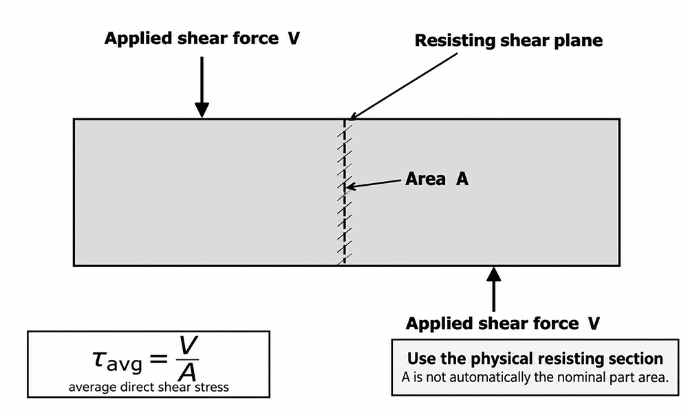
A practical shear stress definition is force per unit area acting parallel to the section that resists sliding. The shear stress symbol is τ. In direct shear, the average shearing stress is calculated from the applied shear force and the resisting area.
τ = V / A
| Symbol | Meaning | SI unit | Decision use |
| τ | Average direct shear stress | MPa or N/mm² | Compare demand with a valid material or joint capacity. |
| V or F | Shear force or shear load | N | Use the force actually transferred through the checked plane. |
| A | Resisting shear area | mm² | Use the physical section that can slide or fracture, not an arbitrary nominal area. |
Because 1 N/mm² equals 1 MPa, common shear stress units can be written as either N/mm² or MPa. A 20,000 N shear load over 100 mm² therefore gives 200 MPa average shear stress. This shear stress calculation is simple enough to do by hand; a shear stress calculator can automate the arithmetic, but it cannot decide which plane or area is physically carrying the load.
1.1 Average and Direct Shear Stress: Choosing the Shear Area
Direct shear stress uses an average stress over an assumed plane. It does not reproduce the local shear stress distribution around a hole, thread run-out, notch, shoulder or contact edge. For a solid round pin or plain bolt shank, one shear plane uses the circular section area. Two shear planes use two such sections only when both planes exist and the geometry supports load sharing.
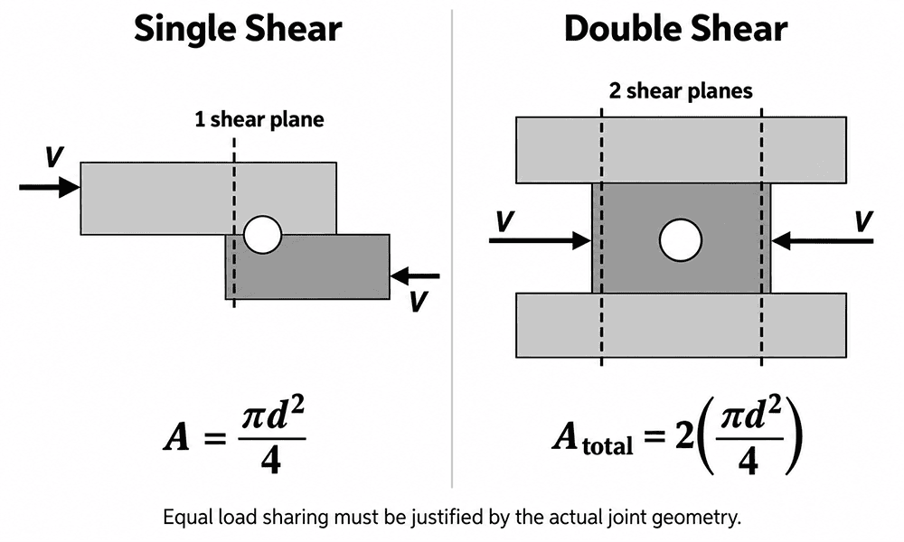
A = πd² / 4 | A_double = 2(πd² / 4)
Thread location changes the result. A bolt shear calculation based on nominal diameter can overstate area when the shear plane crosses the threaded section. For a double shear bolt with both planes through the plain shank, the plain-shank diameter is the relevant first-pass area. For threads in the plane, use the effective section required by the applicable fastener design method.
For machined features, the calculation should be tied to the drawing. DFM design guidelines for machined holes and joints help connect hole geometry, edge distance and manufacturability to the load path rather than treating the fastener in isolation.
2. Shear Force, Shear Stress, Shear Strain and Shear Strength
Shear force, shear stress, shear strain, shear modulus and shear strength answer different questions. Keeping those quantities separate prevents a common design error: comparing an applied force directly with a material strength or treating stiffness as strength.
| Quantity | Meaning | Typical unit | Use in a design check |
| Shear force / shear load | External transverse load to be transferred | N | Defines the demand before geometry is considered. |
| Shear stress | Load divided by a resisting area | MPa | Checks demand on a selected shear plane. |
| Shear strain | Angular deformation caused by shear | dimensionless | Describes deformation, not capacity. |
| Shear modulus / modulus of rigidity | Elastic relation between shear stress and shear strain | GPa or MPa | Used for elastic shear deformation. |
| Shear strength | Material or connection resistance under stated conditions | MPa | Provides capacity only when the source and condition are valid. |
2.1 Shear Force vs Shear Stress, and Normal Stress vs Shear Stress
Shear force is a load; shear stress is the internal demand created when that load passes through an area. That is why a shear force formula and a shear stress formula are not interchangeable. Normal stress acts perpendicular to a section, while shear stress acts parallel to it. A fastener can carry bolt tensile stress from preload while the joint also sees transverse loading. A shaft can carry torsional stress while also carrying bending or axial load.
For an engineer comparing shear stress vs normal stress or shear stress vs tensile stress, the first question is direction and load path. For shear stress vs shear strain, the distinction is demand versus deformation. Under linear elastic behavior, shear stress and shear strain are related by the shear modulus G:
τ = Gγ
This relation describes elastic shear deformation. It is not a shear strength formula and it does not provide allowable shear stress.
2.2 Shear Strength, Shear Fracture and Allowable Stress
Shear strength is capacity; calculated shear stress is demand. Material shear strength, yield shear strength, ultimate shear strength and allowable shear stress are not interchangeable labels. Their meaning depends on the material grade, condition, test method, loading mode and design rule. When comparing candidate materials for a shear-loaded part, a metal strength chart for CNC materials can help engineers review yield strength, tensile strength, hardness and other basic mechanical properties before applying a design-specific shear criterion.There is no universal factor of safety shear stress value and no universal conversion from tensile strength to shear strength.
That boundary is especially important when reading a material certificate or handbook. The separate EPOC CRAFTER guide on yield strength vs tensile strength for CNC part selection explains why yield and ultimate tensile values serve different design purposes. The same discipline applies to shear strength vs tensile strength: use a documented relationship only when the material model, specification or design standard provides one.
A shear failure or shear fracture can also be preceded by another failure mode. In a pin joint, bearing deformation or hole growth can control before the pin reaches its pin shear strength. In a preloaded joint, slip can move the load path into bolt bearing before bolt shear failure becomes the governing check.
3. Single Shear vs Double Shear and Shear Pin Checks
Single shear vs double shear is a question of how many resisting shear planes carry the load. Single shear and double shear describe the number of resisting shear planes. The arithmetic is simple; the engineering question is whether the planes and load sharing are real.
| Configuration | Resisting area for a round pin | Average stress | Use only when |
| Single shear | A = πd²/4 | τ = V/A | One physical shear plane carries the checked load. |
| Double shear | 2A = 2(πd²/4) | τ = V/(2A) | Two planes carry the load and the assumed sharing is credible. |
| Thread in shear plane | Not automatically πd²/4 | Use the effective section required by the design method | Thread geometry lies in the resisting plane. |
| Clearance or misalignment present | Nominal area may still be used for first-pass pin shear stress | Add bearing, bending and contact checks | The average result is treated as screening, not full joint capacity. |
3.1 What Is Double Shear, and Why Is It Not Automatically Twice the Joint Capacity?
In ideal double shear, the total resisting pin area is twice the single-shear area, so the average double shear stress is half the single shear stress for the same total load and diameter. That does not mean every double-shear joint has twice the usable capacity. Hole alignment, diametral clearance, pin bending, bearing stress, edge geometry and cyclic contact can redistribute the load.
A shear pin or pivot bolt should therefore be checked as a connection. Pin shear stress and pin shear strength are only part of the review. A single shear stress check can miss bending in an offset lap joint. A double-shear calculation can miss unequal ear contact in a clevis.
3.2 EPOC CRAFTER Case: Average Bolt Shear Was Not the Controlling Problem
An anonymized EPOC CRAFTER industrial-automation clevis used a partially threaded M12 × 1.75 property class 10.9 bolt as the pivot. Both shear planes crossed the plain shank. The measured minimum shank diameter was 11.88 mm, so the total double-shear area was 221.7 mm². The nominal reversing load was ±22 kN, and an in-line load cell recorded a 38.0 kN peak during actuator deceleration.
For machined pins, shafts and other load-bearing components, comparing 4140 vs 1018 vs 1045 steel for load-bearing CNC parts helps clarify how strength, hardness, machinability and heat-treatment condition affect the final design.
τ_avg = 38,000 / 221.7 = 171 MPa | τ_avg at 22 kN = 99 MPa
The original hand calculation stopped at nominal double shear stress. Service evidence pointed elsewhere. Before service, the three holes measured 12.15, 12.18 and 12.16 mm against an 11.88–11.90 mm shank. After about 180,000 reversing cycles, the center-lug hole measured 12.24 mm, with polished witness bands, fretting and directional contact marks. The bolt had not fractured.
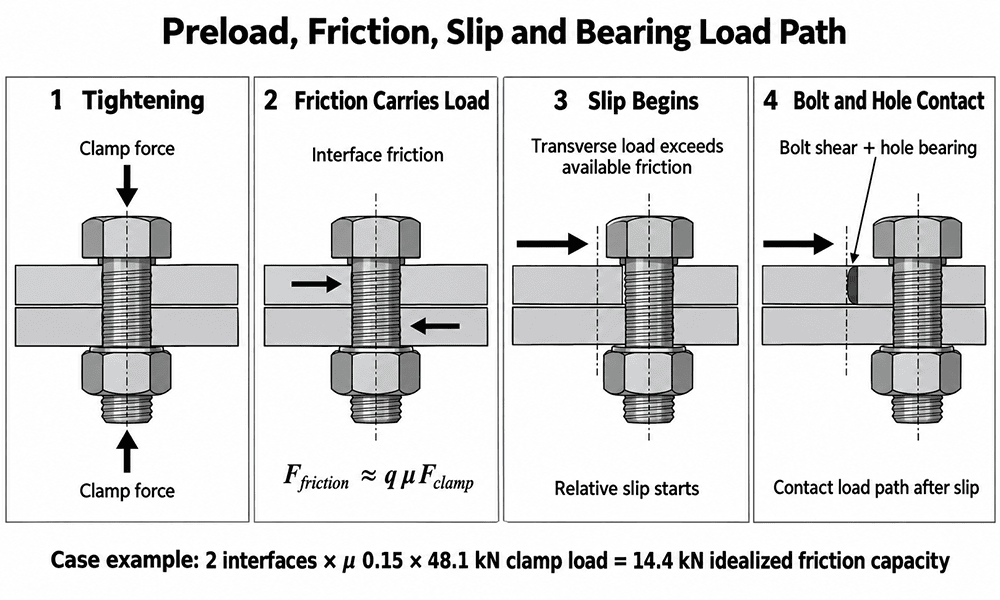
The joint had two clamped interfaces, an interface friction coefficient of μ = 0.15 and a measured clamp load of 48.1 kN. The idealized friction capacity was 14.4 kN, below both the 22 kN nominal and 38.0 kN peak transverse loads. Joint slip was therefore expected, so the service load moved into bolt shear and hole bearing contact. The engineering problem was clearance and repeated bearing impact, not average bolt shear stress alone.
The redesign used a Ø14 precision shoulder bolt, Ø14 H7 holes and tighter common-axis and parallelism controls. At a 42 kN bench proof load, lateral movement fell from 0.31 mm to 0.07 mm. After 250,000 production cycles, inspection found no measurable bore growth beyond 14.021 mm and no new directional hole elongation. These results apply to the recorded load spectrum and indoor 18–34 °C environment; they are not a universal fatigue-life claim.
EPOC CRAFTER shop-floor data: Anonymized case SS-CLEVIS-12-01. Measured dimensions, load-cell data, clamp-load trials, CMM/bore-gauge inspection and proof-load displacement are from the completed internal case record.
4. Shear Stress in Pins and Shafts
Pins and shafts can both carry shear, but the stress model is different. A pin in a clevis or lap joint is usually a direct shear and bearing problem. A circular shaft transmitting torque is a torsional shear problem. For highly loaded shafts, the sequence of heat treatment before or after CNC machining can also affect hardness, residual stress, dimensional stability and the amount of material that must remain for final machining.
4.1 Bearing Stress, Hole Fit and Pin Load Sharing
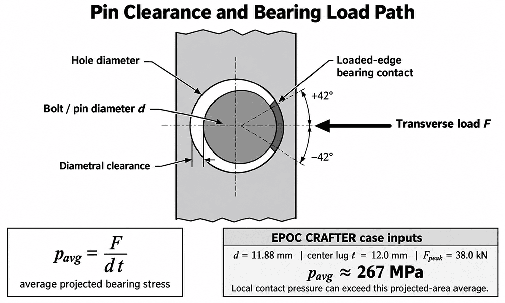
A first-pass bearing stress uses the projected contact area between a pin or bolt and the loaded plate or lug:
p = F / (d t)
This is average projected bearing stress, not the maximum local contact pressure. Clearance, edge contact, hole position and deformation can increase the local peak. In the clevis case, the 12.0 mm center lug gave 142.6 mm² projected area and 267 MPa average bearing stress at 38.0 kN. Each 8.0 mm outer ear carried about half the transverse load, giving about 200 MPa average bearing stress per ear. Those values describe the projected-area check only.
The fit and alignment that create this load path are manufacturing requirements. Use ISO 286 clearance and interference fits for CNC parts when a hole-shaft fit is intentionally specified, and use CNC tolerances and standards for critical features to keep size, position, coaxiality and other acceptance requirements separate.
4.2 Torsional Shear Stress in Shafts
For a circular shaft, the torsional shear stress formula, also called the torsion shear stress formula, is τ = Tr/J. The torsional shear stress increases with radius and reaches its maximum shear stress at the outside surface. For a solid round shaft, J = πd⁴/32, so the maximum shear stress in shaft torsion becomes 16T/(πd³). This is shear stress due to torque, not the V/A direct-shear model used for a pin. In practical terms, what is torsional shear stress? It is the shear stress created by torque acting through a shaft section.
τ = Tr / J | solid round shaft: τ_max = 16T / (πd³)
This section does not expand into principal stress, Mohr circle or full stress transformation because those topics move away from the article’s direct search intent. Where combined loading controls, use the appropriate combined-stress method rather than forcing a torque shear stress problem into a direct-shear equation.
5. Bolt Shear Stress, Bolt Preload, Slip and Bearing
A transverse load on a preloaded bolt does not automatically become bolt shear load. In a friction grip joint, the intended first load path is interface friction created by bolt preload and bolt clamping force. Direct shear stress in bolts and bolt bearing become relevant when available friction is insufficient, joint slip occurs, overload changes the load path, or the connection is intentionally designed as a shear-bearing or body-fit joint.
5.1 Bolt Preload, Bolt Pretension and Clamping Force
Bolt preload, or bolt pretension, is the tensile force created during tightening. Clamping force is the corresponding compressive force in the joint. A bolt preload calculation cannot be reduced to torque alone because friction, tightening scatter, embedding, temperature and bolt relaxation change the achieved and residual clamp load.
VDI 2230 Blatt 1:2015-11 treats minimum and maximum assembly preload, required minimum clamp load, preload changes, working stress, fatigue, bearing-surface pressure, thread engagement, slipping and shearing as separate checks. Its official VDI page still lists the Part 1 publication date as 2015-11 and describes the method for highly stressed joints with one cylindrical bolt.
F_Mmax = α_A F_Mmin
Standard basis: VDI 2230 Blatt 1:2015-11, Systematic calculation of highly stressed bolted joints, joints with one cylindrical bolt.
5.2 Joint Slip, Bolt Bearing and Bolt Shear Capacity
For transverse loading, VDI 2230 first checks whether the clamped interfaces can carry the load by friction. Dynamic transverse loading requires care with the friction basis. If the friction path is insufficient, the load can move into bolt slip, bolt bearing stress and direct bolt shear stress.
That sequence changes how you interpret bolt shear strength, shear strength of bolts and bolt shear capacity. A bolt shear strength formula by itself does not prove a bolted joint is safe. The joint still needs the correct shear plane, material property basis, safety factor, bearing check and load-sharing model. ISO 898-1:2013 can provide the mechanical-property basis for property-class fasteners, but it is not a direct joint shear allowable standard.
Fastener property basis: ISO 898-1:2013 is the current published edition listed by ISO for bolts, screws and studs with specified property classes; a revision project is under development.
5.3 Joint Opening, Bolt Fatigue, Thread Stripping and Preload Loss
A bolted joint design can pass a nominal bolt shear check and still fail by joint opening, joint separation, bolt fatigue, thread stripping, bolt bearing failure or preload loss. Eccentricity adds bending and can change contact. In the EPOC CRAFTER case, a 2.0 mm measured load offset at 38.0 kN created a 76 N·m joint moment. That is why bolt tensile stress, transverse load and contact geometry must be reviewed together when the load path is not concentric.
The same logic applies to fastener failure in cyclic service. Fretting and hole growth can appear before fracture. Bolt relaxation or embedding can reduce clamp load. A screw shear strength value does not capture these mechanisms. Because bolt and joint behavior depends strongly on the actual material condition, engineers should verify the relevant yield strength, tensile strength and hardness of CNC metals instead of relying on a generic material name alone.
5.4 VDI 2230 Bolt Calculation: Scope and Boundary
The VDI 2230 bolt calculation is a systematic bolted joint calculation for highly stressed single-bolt joints. It is not a universal shear test standard. It should not be extended to every pin, key, beam or thin plate, and it does not justify converting tensile strength to a universal allowable shear stress. Its Part 1 method also should not be presented as the multiple-bolt method in Part 2.
When the standard’s friction, contact or loading assumptions do not describe the real joint, or when severe impact, corrosion, random loading or complex contact controls, add experimental validation, FEA or another applicable design method. This is the correct boundary for VDI bolt calculation and for any simplified bolt shear calculation.
6. When τ = V/A Is Not Enough
The direct shear equation is a screening tool. Transverse shear stress in a pin or fastener can often start with V/A, but only after the load path and resisting plane are identified. Move beyond it when local stress distribution, contact, clearance, eccentricity, combined loading or cyclic behavior changes the load path. The most useful decision is not whether V/A is mathematically correct, but whether its assumptions still describe the part.
| Situation | First-pass equation | Additional check | Decision boundary |
| Known direct shear plane | τ = V/A | Material or connection capacity | Use when the resisting plane is clear and stress distribution is not the governing issue. |
| Pin or bolt with clearance | τ = V/A | Bearing, bending, fit, edge distance | Average shear can be low while local hole contact controls. |
| Circular shaft under torque | τ = Tr/J | Combined loading if present | Use torsional shear, not direct V/A. |
| Preloaded transverse bolted joint | Friction/slip check first | Preload, residual clamp load, bearing, bolt shear | Do not assume the full transverse load enters the shank before slip. |
| Eccentric or cyclic joint | No single scalar check | Bending, opening, fatigue, fretting, contact | Escalate to a fuller model, FEA or test when interactions control. |
When analytical assumptions are uncertain, CNC machining for functional load-testing prototypes allows the design team to evaluate the real material, geometry, fit and load path before committing to production tooling or higher-volume manufacturing.
Inspection has to match the assumption. The EPOC CRAFTER case used CMM for hole position and coaxiality, a three-point bore gauge for hole diameter, a micrometer for shoulder diameter, a calibrated torque wrench, a load washer, an in-line load cell and a dial indicator. For features where fit or alignment drives load sharing, tight tolerance machining for critical CNC features gives the drawing and inspection context for deciding which characteristics deserve tighter control.
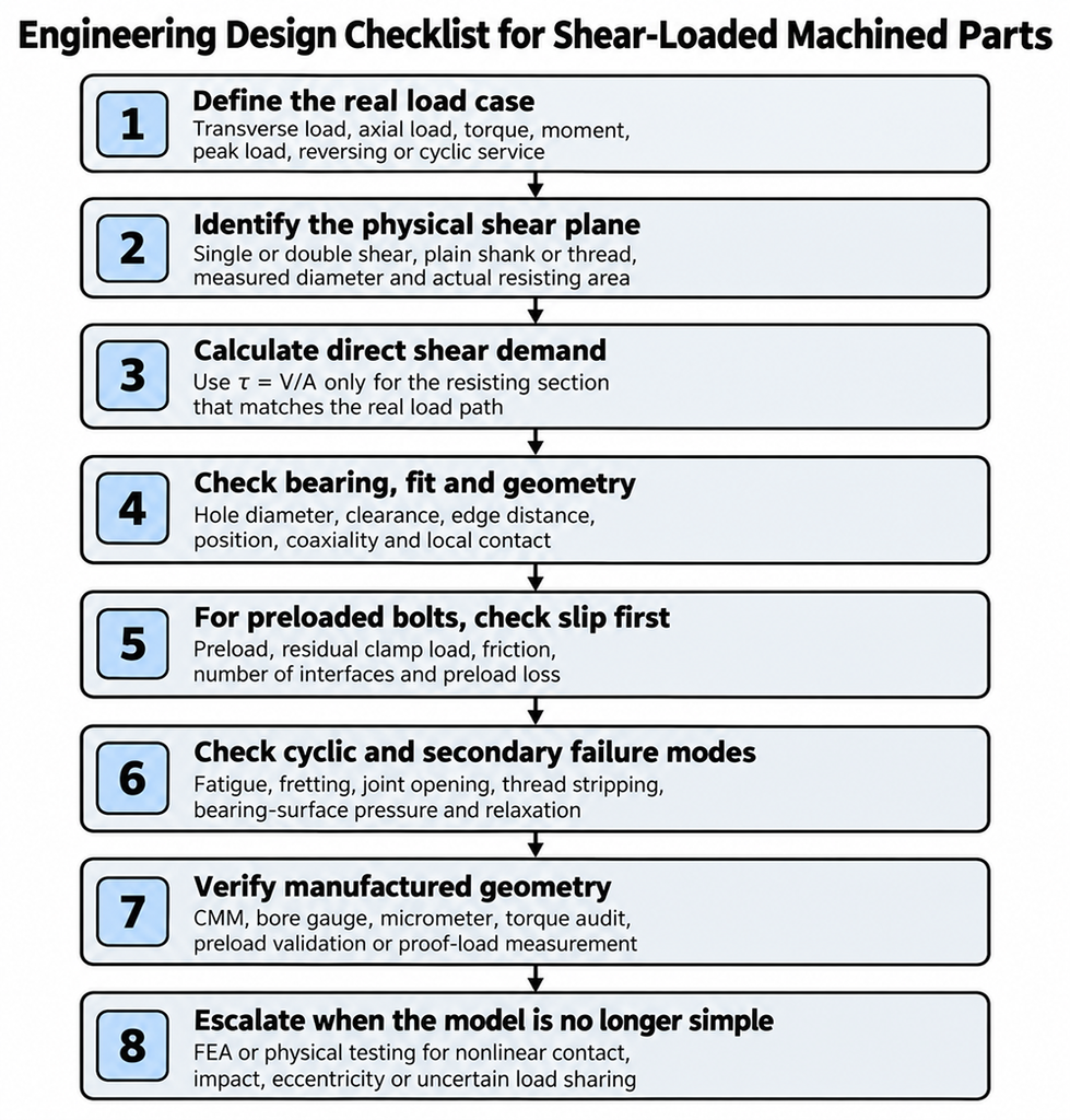
7. Engineering Design Checklist for Shear-Loaded Machined Parts
| Check | Record or calculate | Engineering decision |
| Load case | Record transverse force, axial force, torque, moment, load direction, offset, cycle type and measured peak load where available. | Do not size from a nominal actuator or motor rating when a measured service peak exists. |
| Shear plane | Identify plain shank, thread root, pin section and number of planes. | Use the section that physically resists sliding or fracture. |
| Demand vs capacity | Calculate shear stress separately from material or joint strength. | Do not use tensile strength as a universal shear allowable. |
| Pin and hole | Check bearing stress, edge distance, clearance, alignment and deformation. | A pin can remain intact while the hole grows. |
| Preloaded bolt | Check bolt preload, clamping force, friction, residual clamp load and slip before direct bolt shear. | A friction grip joint and a shear-bearing joint do not share the same first check. |
| Cyclic service | Check fretting, impact at reversal, preload loss, bolt fatigue and hole growth. | A static shear strength comparison does not establish fatigue life. |
| Inspection | Select bore gauge, micrometer, CMM, torque audit, preload validation or proof-load displacement as needed. | Measure the geometry and assembly variables used in the calculation. |
| Escalation | Use FEA or physical testing for complex contact, significant eccentricity, nonuniform sharing, impact or safety-critical consequences. | Do not make a simple formula carry assumptions it was not built to represent. |
For a supplier review, the drawing and load assumptions should travel together. EPOC CRAFTER’s CNC machining for load-bearing parts page gives the manufacturing context for machined bores, shoulders, datums and inspection features that carry these design decisions into production.
8. Frequently Asked Questions
8.1 What Is Shear Stress?
Shear stress is force per unit area acting parallel to a resisting section. What causes shear stress is a force component parallel to that section. For average direct shear, use τ = V/A. What are the units of shear stress? In this article, N/mm² and MPa are used, and they are numerically equivalent.
8.2 How Is Shear Stress Calculated in a Bolt or Pin?
What is direct shear stress? It is the average stress on a section resisting a direct transverse load. For a round plain shank in one plane, calculate A = πd²/4 and then τ = V/A. For two credible shear planes with equal load sharing, use twice that area. A complete bolt shear calculation also checks thread position, bearing, preload, fatigue and the applicable design basis.
8.3 What Is Single Shear vs Double Shear?
What is single shear? It has one resisting plane. Double shear has two. Under ideal equal load sharing, the same pin and total load produce half the average double shear stress of single shear, but the complete joint can still be limited by bearing, bending, clearance or unequal contact.
8.4 What Is Shear Strength, and How Is It Different from Shear Stress?
Shear stress is calculated demand; shear strength is capacity from a material test, specification, validated model or design rule. What is allowable shear stress? It is a design limit established from an applicable material or connection basis and safety factor, not a universal fraction of tensile strength. What is shear failure? It is failure governed by shear demand exceeding the relevant capacity or by a shear-related connection mode.
8.5 What Is Bearing Stress in a Bolted or Pinned Joint?
Bearing stress is the compressive contact stress where a pin or bolt pushes against the hole wall. A common preliminary bolt bearing stress check is p = F/(dt), using projected area d×t. Local contact pressure can be higher when clearance or misalignment concentrates the load.
8.6 What Is Bolt Preload, and When Does a Bolt Actually Carry Transverse Shear?
Bolt preload is the tensile force created during tightening; it produces clamping force at the joint interface. In a friction grip joint, transverse load is intended to pass through interface friction while sufficient residual clamp load remains. After joint slip, overload, or in an intentional shear-bearing design, bolt shear and bearing become direct load paths. This is why a request for how to calculate bolt shear strength must start by identifying the joint load path and the shear plane.
A useful shear calculation starts with the physical load path. For a pin, locate the real shear planes and check the hole. For a shaft, use torsional shear. For a preloaded bolt, establish clamp load and slip behavior before assuming the shank carries the full transverse force. The EPOC CRAFTER clevis case shows why this sequence matters: the average double-shear calculation was valid, but measured clearance and insufficient friction capacity drove slip, fretting and hole growth before bolt fracture. A drawing that defines fit, alignment, material condition, preload method and inspection route gives manufacturing and quality a load path they can reproduce, which is why understanding ISO 2768 Edition 2 CNC drawing requirements is important when general tolerances and drawing rules are part of the specification.
Ready to Quote Your CNC Prototype?
Upload your STEP file and get a DFM review + quote within 12 hours.
No tooling cost. Minimum 1 part.
