

Dewey Wu General Manager & senior mechanical engineer at EPOC CRAFTER, 15 years in design engineering, quality, and metallurgy. Hands-on across CNC machining, metalwork, sheet metal, and prototyping (subtractive + 3D printing).
Sinker EDM removes material from an electrically conductive workpiece through controlled electrical discharges between a shaped electrode and the workpiece in a dielectric medium, per VDI 3400:1975. The industry also calls it die sinking EDM, ram EDM, or plunge EDM. You reach for it when CNC milling cannot get into the cavity or hold the corner. Hardness alone is not the trigger; the workpiece has to conduct, and the geometry has to defeat a rotating cutter. This guide covers how the process works, how the electrode and discharge gap behave, what the VDI 3400 surface classes and ISO 21920 profile parameters mean on a drawing, where recast layer and heat-affected zone become surface-integrity concerns, and what a sinker EDM RFQ needs to say so a supplier does not guess.
1. What Sinker EDM Is (and What the Common Names Mean)
Sinker EDM belongs to the spark-erosion (Funkenerosion) family in VDI 3400:1975, under the branch called Funkenerosives Senken. Wire cutting sits in a separate branch (Funkenerosives Schneiden mit Draht oder Band), so a drawing that says only “EDM” leaves real ambiguity for the supplier. The tool is a shaped positive of the cavity you want, which VDI 3400 calls a Formelektrode. The electrode advances toward the workpiece along a controlled feed axis, and material comes off through repeated electrical discharges, not through a rotating cutter.
Different shops use different names for the same process:
- Sinker EDM: US and UK industry default.
- Die sinking EDM: European tool-and-die usage.
- Ram EDM: from the ram-style Z-axis feed.
- Plunge EDM: from the plunge-cut motion.
- Cavity EDM and Vertical EDM: less common labels for the same process.
- Die sinker EDM: older US shop-floor label.
All point at the same VDI 3400 Senken process. The branch that is a physically different process is wire EDM, which uses a moving conductive wire instead of a shaped electrode and belongs under the Schneiden branch of the same standard.
VDI 3402 Blatt 4:1994 makes the workpiece rule explicit: any electrically conductive material can be eroded, even in the hardened state. So the qualifier that matters on your drawing is electrical conductivity plus geometry that a rotating cutter cannot reach. Hardness alone will not put a part on a sinker EDM machine. Ceramics with an insulating surface, most polymers, and heavily oxidized surfaces will not erode until you strip the oxide, treat the surface, or apply a conductive coating.
Sinker EDM sits next to precision CNC machining capabilities in a typical tool-and-die workflow, and a mold shop routinely runs both on the same part.
2. When Sinker EDM Wins Against CNC and Wire EDM
Three signals move a part off CNC and onto sinker EDM in your process plan:
- The internal corner is smaller than the smallest usable end-mill radius. A 0.2 mm internal fillet in a mold cavity has no tool that can hold it in hardened steel. A sinker electrode reproduces the electrode shape plus the discharge gap.
- The cavity is blind and deep. Depth-to-width above 3:1 in hardened steel bends end mills and pulls dimensions out of the print. A shaped electrode advances without side load.
- The material is already hardened. Once tool steel is at HRC 55 to 62, milling is fighting the material. VDI 3402 Blatt 4:1994 states that spark erosion applies to workpieces in the hardened condition.
Wire EDM is a different tool with a different job. It threads a moving wire through a pre-drilled start hole and follows a 2D or ruled 3D contour. A blind cavity, a complex 3D closed pocket, or an internal shape with no exit does not fit wire EDM at all.
Use this comparison at the RFQ stage:
| Requirement | Sinker EDM | Wire EDM | CNC Milling |
| Blind cavity, complex 3D shape | Applicable | Not applicable | Limited by tool reach |
| Sharp internal corner in hardened steel | Applicable | Not applicable | Radius-limited |
| Through-cut 2D or extruded profile | Overkill | Applicable | Applicable in soft metal |
| Bulk removal from a soft billet | Slow | Slow | Faster and cheaper |
| Cutting force distorts thin walls | Zero force | Zero force | Deflection risk |
| Rotating tool can reach the feature | Slower and pricier | Not applicable | Choose CNC |
Sinker EDM earns its cost only when at least one of these constraints is real. When milling can hold the geometry and the finish on your part, milling stays faster and cheaper.
3. How the Process Works (Discharge, Servo, Dielectric, Flushing)
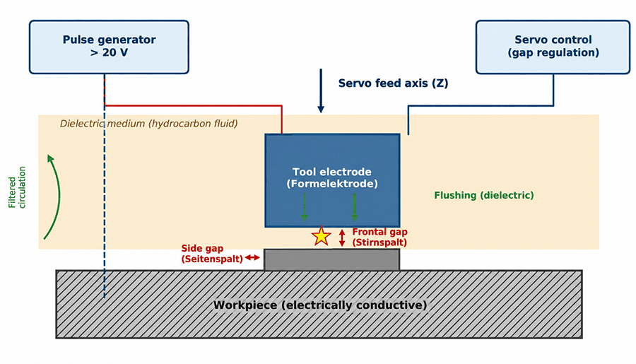
The pulse generator, feed axis, and dielectric system work as one control loop.
The generator delivers voltage pulses above 20 V to the electrode. When the applied voltage exceeds the dielectric breakdown strength across the gap, a plasma channel forms and a spark discharges. VDI 3400 defines this as Funkenerosion: material comes off through repeated non-stationary discharges, not through a continuous arc.
The servo axis controls how close the electrode sits to the workpiece. That distance is the working gap (Wirkspalt in VDI 3400), split into a frontal gap along the feed direction and a side gap perpendicular to it. Servo response holds the gap steady. When debris packs the gap, current climbs, the servo backs the electrode off, and the discharge stabilizes again. A short circuit (Kurzschluss) is metal-to-metal contact, and the standard names it as a real operating state. Your electrode does not always float free.
The dielectric medium does four jobs at once, per VDI 3400 §2.1.3:
- forms a controlled discharge channel between the electrodes
- carries eroded particles out of the spark gap
- carries decomposition products out of the same gap
- absorbs heat generated at the electrode
Flushing is the forced replacement of dielectric inside the gap. VDI 3402 Blatt 4:1994 §5.1.2.1 lists four methods for sinker EDM: pressure flushing through the electrode or through the workpiece, suction through either side, combined pressure and suction, and jet flushing. When flushing channels disturb the process or the geometry cannot accept them, cyclic lifting of the electrode generates a pumping effect and refreshes the gap between passes.
4. Overcut, Side Gap, and Why the Electrode Is Not the Cavity
“Overcut” is what shops write in emails. The formal term in the source standard is different. VDI 3400:1975 defines two components of the working gap: the frontal gap (Stirnspalt) along the feed direction, and the side gap (Seitenspalt) perpendicular to it. Together they form the Wirkspalt.
For a circular test recess, the standard’s own measurement method gives:
D_recess − D_electrode = 2 × side gap
Your cavity finishes wider than the electrode by twice the side gap on the diameter. The electrode is undersized in every direction when the machined feature has to sit inside a tolerance band. VDI 3402 Blatt 4:1994 writes this into electrode design directly: the tool electrode must be undersized in all directions to account for the discharge gap.
The gap value is not a single number. It moves with pulse duration, peak current, voltage, dielectric condition, and flushing state, all called out in VDI 3400 §1.4.3 as coupled variables. Finishing pulses report in the low micrometer range; roughing schedules run larger. You settle on a real gap by qualifying the specific pulse schedule against a witness coupon. NASA-STD-6016C w/Change 1 MPR 170 writes this discipline into spaceflight hardware: qualify the EDM schedule to establish the maximum affected-layer thickness and the gap before quoting removal or analysis.
Two design consequences follow:
- Sharp inside corners. A drawn inside corner near 0.05 mm needs an electrode radius equal to that value minus the finishing gap. Below the finishing gap, a physical corner does not resolve.
- Deep features. Side gap accumulates along the depth. A slot beyond 20:1 depth-to-width can open wider at the top than at the bottom unless the pulse schedule is stepped or the electrode is orbited.
5. Electrode Materials: Graphite vs Copper vs Tungsten-Copper
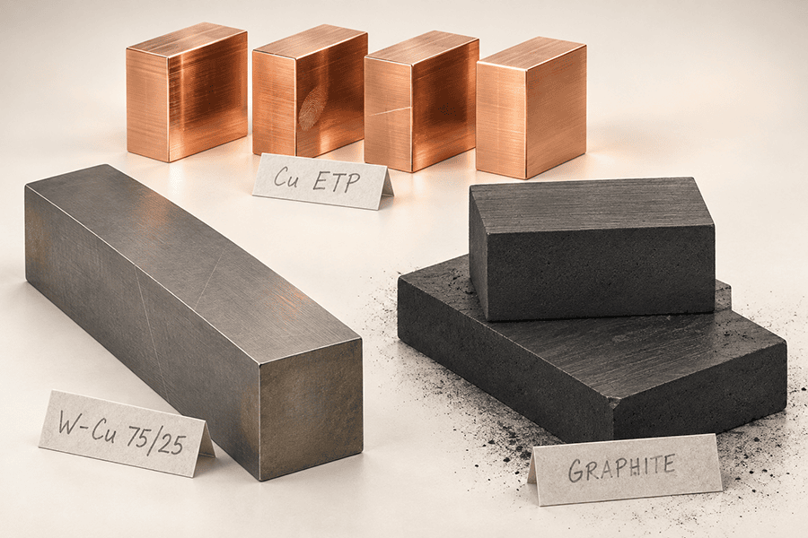
The three electrode materials named directly in VDI 3402 Blatt 4:1994 §7.1 for sinker EDM are graphite, electrolytic copper, and tungsten-copper. Each fits a different pass in the same job.
Graphite carries the roughing pass. VDI 3402 Blatt 4 states that graphite delivers good removal-to-wear performance during roughing, machines easily, and stays workable for large electrode volumes. The standard names its drawbacks directly: a tendency to arc, and a fire hazard from the dust. You shape graphite fast on a CNC mill, run it at high peak current, and accept a coarse surface.
Electrolytic copper carries the finishing pass. VDI 3402 Blatt 4 recommends it for surface qualities of comparison class 27 and finer. Copper deforms less under mechanical load than graphite, holds edge detail on small features, and produces a more stable discharge at finishing energy. The tradeoff is heat: thin copper electrodes distort under high thermal loading, and the standard flags this as a real design constraint.
Tungsten-copper appears when wear has to be minimal or when the workpiece is hardmetal. VDI 3402 Blatt 4 states tungsten-copper has proven suitable for both cases. It is expensive to machine, so you use it only on the finish pass or on the small features that drive the final tolerance.
Read the tradeoff at the RFQ stage:
| Criterion | Graphite | Electrolytic Copper | Tungsten-Copper |
| Preferred pass | Roughing | Finishing to VDI class 27 and finer | Low-wear finishing or hardmetal |
| Removal rate | High | Moderate | Low |
| Edge and detail retention | Moderate | Good | Best |
| Heat distortion risk | Low | Notable on thin sections | Low |
| Electrode machinability | Fast on standard CNC | Slower, needs coolant control | Slow, hard to machine |
| Cost per electrode | Low | Moderate | High |
| Named hazard in VDI 3402 | Arc tendency, dust fire hazard | Thermal deformation on thin walls | Not flagged |
Most cavities run two or three electrodes in a graphite-roughing plus copper-finishing flow, with tungsten-copper reserved for one or two critical features. When your RFQ lists a single electrode, you are asking for a compromise between roughing speed and finishing quality that neither material delivers.
For the workpiece side of the same cavity, the material properties reference for tool steels and superalloys covers the machining behavior.
6. Electrode Wear, Multi-Electrode Strategy, and What Drives Cost
Every discharge erodes both sides of the gap. VDI 3400:1975 §1.4.1.2 splits the wear side into three defined quantities:
- Verschleißrate. Volume of tool electrode removed per unit time.
- Impulsverschleiß. Volume of tool electrode removed per discharge pulse.
- Relative electrode wear. Verschleißrate divided by Abtragrate, expressed as a percentage.
A single “wear number” means nothing until you tag which quantity it belongs to. VDI 3400 also names edge wear and length wear as geometry-specific quantities that require the measurement method alongside the value.
Wear moves your cavity. A worn roughing electrode leaves oversized volume and rounded corners; a worn finishing electrode leaves the cavity undersized. The answer in the shop is not one electrode. VDI 3400 §1.4.3 states it directly: MRR, wear, gap width, and surface quality are coupled outcomes.
A workable multi-electrode plan for a hardened steel cavity:
- Rough electrode (graphite): takes the bulk of the volume, oversized to leave finishing stock.
- Semi-finish electrode (graphite or copper): trims walls to near-net, sized against the finishing gap.
- Finish electrode (copper or tungsten-copper): carries micrometer-scale stock, sized for final dimension and VDI surface class.
Cost follows the electrode plan, not the burn time. VDI 3402 Blatt 4:1994 §7.2 names eight variables that drive sink-EDM electrode selection at the RFQ stage: accuracy requirements, wear behavior, removal rate, surface quality, total removal volume, electrode volume, complex-form manufacturability, and machine load capacity. A print sent without those inputs gets quoted on three electrodes and one setup; when the reality needs five electrodes and two setups, price and lead time both change.
7. Surface Finish: VDI 3400, Ra, Rz, and How to Read the Chart
An EDM surface gets described two ways on the same drawing: a VDI 3400 comparison class, or a profile parameter like Ra or Rz under ISO 21920-2:2021. They are related, they are not the same, and mixing them is where drawings go wrong.
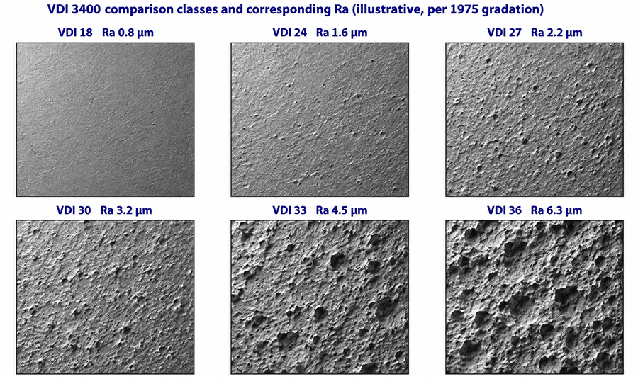
VDI 3400:1975 §1.4.1.3 built a comparison-sample system for shops without stylus roughness testers. The gradation is logarithmic: class N gives Ra = 0.1 × 10^(N/20) µm.
| VDI class | Ra (µm) |
| 0 | 0.100 |
| 12 | 0.4 |
| 18 | 0.8 |
| 20 | 1.00 |
| 24 | 1.6 |
| 27 | 2.2 |
| 30 | 3.2 |
| 33 | 4.5 |
| 36 | 6.3 |
| 40 | 10.0 |
VDI 3400 labels these as recommended comparison references. The 1975 standard does not write them as mandatory acceptance criteria. A drawing that writes “VDI 30” without a parameter, a tolerance limit, and an acceptance rule leaves the shop and the inspector to argue after machining.
ISO 21920-2:2021 fixes the three most-used profile parameters on a scale-limited profile:
- Ra. Arithmetic mean of the absolute ordinate values of the roughness profile over the evaluation length.
- Rz. Mean, across section lengths, of the largest peak height plus the largest pit depth per section.
- Rt. Largest height plus largest depth over the whole evaluation length.
Rz is not a single peak-to-valley figure; Rt is. Two surfaces at the same Ra can carry different Rz and Rt because Ra averages the profile while Rz and Rt track extremes. On an EDM surface with isolated deep craters, Rt sits well above Ra, and your “Ra 1.6 µm” callout will not catch them.
Our ISO 21920 callouts example from a micro-milling feature walks through the drawing mechanics on a real part.
8. Surface Integrity: Recast Layer, White Layer, HAZ, and Microcracks
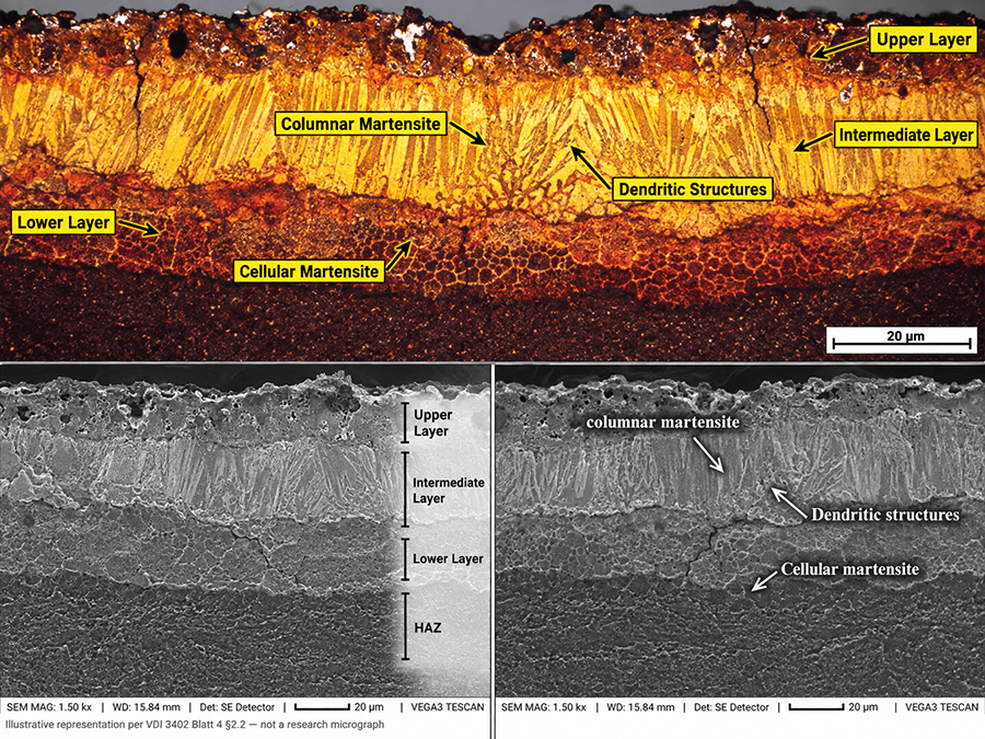
Ra tells you nothing about what happened under the surface. Surface texture, per ISO 21920-2:2021, covers geometrical irregularities in a scale-limited profile; surface integrity is a separate topic and covers the metallurgical state of the top layer. Two EDM surfaces at the same Ra can carry different recast thicknesses, different residual stress, and different fatigue lives.
VDI 3402 Blatt 4:1994 §2.2 describes the EDM zone on steels as two stacked layers: a “weiße Schicht” (resolidified melt) in the micrometer range, over a tempered transformation zone. Penetration depth depends on the pulse schedule. The standard does not lock a maximum white-layer thickness for all cases.
§6.3 Nachbehandlung sets what follows the EDM pass: wash or blast off loose deposits, stress relieve the steel because spark erosion produces surface tensile stress (methods named in the standard are tempering, blasting, magnetic pulsing, and vibration), and evaluate the surface zone before nitriding or PVD coating.
For mission-critical spaceflight parts, NASA-STD-6016C w/Change 1 §4.2.4.9 (2023-11-15) sets four requirements:
- MPR 167. Control the depth of oxide, recast, and HAZ.
- MPR 168. Remove the oxide layer.
- MPR 169. Remove recast and HAZ from bearing, wear, fatigue-critical, fracture-critical, and crack- or notch-sensitive surfaces; leave them in place only when an engineering evaluation shows they are non-consequential.
- MPR 170. Qualify the EDM schedule to establish the maximum affected-layer thickness.
The NASA standard applies to spaceflight hardware, not commercial molds. Cite it on a print only to show what a fully qualified surface spec looks like. On a fatigue-loaded medical or aerospace part, run the same logic at a milder level: strip oxide, evaluate recast, and decide whether the finish pass alone leaves an acceptable surface for the function.
Post-EDM stress relief and the finishing plan run through surface finishing operations after machining.
9. Achievable Tolerances (Reading VDI Case Data Correctly)
VDI 3400:1975 does not publish a universal sinker EDM tolerance. §3.1 states that spark erosion can meet high requirements for dimensional accuracy, form accuracy, and surface quality. The standard then illustrates what has been achieved through application examples. It does not publish a general capability chart. Read them as case data.
| VDI 3400 example | Accuracy | Surface class | Notes |
| Ex. 4 (warm press die) | ±0.03 mm | Class 12 | Machined after hardening and shrink fitting |
| Ex. 5 (auto mold cutting plate) | Punch/plate agreement ±0.02 mm | Class 36 | Eroded edge area ~5,000 mm |
| Ex. 6 (auto draw die) | ±0.05 mm to electrode at every point | Class 33 | 1,800 × 1,200 mm erosion area |
| Ex. 8 (progressive die tooling) | ±0.005 mm | Class 15 | Workpiece hardened to HRC 62 |
Two lines to keep at the front of your RFQ:
- VDI 3400 case tolerances are examples. They are not a general shop capability. Publishing “±0.005 mm on all sinker EDM parts” reads as a marketing claim without standard backing.
- Your part’s accuracy depends on the eight variables VDI 3402 Blatt 4:1994 §7.2 lists for electrode selection, plus your fixturing, inspection method, and the pulse schedule under a NASA-STD-6016C style qualification per MPR 170. Real numbers come from a qualified schedule on your material and your geometry.
Ask for feature-level tolerance targets on your drawing; a blanket process spec cannot substitute. Tolerance standards and their limits help translate a print callout into an EDM-realistic scope of work.
10. Materials That Sinker EDM Handles and Where It Slows Down
VDI 3402 Blatt 4:1994 §6.1 sets three conditions for erodibility: electrical conductivity, thermal properties, and an oxide-free surface. Hardness is not on that list; §6.2 confirms spark erosion applies to workpieces in the hardened state. VDI 3400:1975 §3.2 adds that a material with a lower melting point and lower thermal conductivity erodes more easily.
The everyday workpiece groups:
- Hardened tool steels: H13, D2, S7 at HRC 55 to 62.
- Titanium alloys such as Ti-6Al-4V.
- Nickel-base superalloys: Inconel 718, Hastelloy.
- Cemented carbide (tungsten-copper electrode territory).
- Copper and aluminum: possible, though rarely the reason you pick EDM.
Two conditions delay the process: heavy surface oxide, and residual magnetism in the erosion zone (VDI 3402 Blatt 4 §6.2 lists both as preparation items). Strip the oxide before start; demagnetize a workpiece that has been on a magnetic chuck.
For the alloy comparison on aerospace and medical parts, our Ti-6Al-4V versus 316L stainless steel comparison walks through what changes with each alloy.
11. Blind Cavities, Deep Pockets, Undercuts, and Flushing Strategy
Deep and blind features earn sinker EDM its cost and expose flushing weakness. VDI 3402 Blatt 4:1994 §5.1.2.1 names four sink-EDM flushing methods: pressure or suction through the electrode or workpiece, combined pressure and suction, and jet flushing. Where no flushing channel can be drilled, cyclic electrode lifting generates a pumping effect between passes.
The same clause warns that complex electrodes can trap combustible decomposition gases in internal cavities; those pockets need Entgasungskanäle (venting channels).
VDI 3402 Blatt 4 §4.5.1 opens features a straight plunge cannot produce. Planetary EDM adds orbital or path-controlled motion to the sinking direction, producing undercuts, single or multi-sided conical holes, and sharp-edged corners with a simpler electrode than a full 3D form would need.
Decide the flushing path before you machine the electrode. Confirm venting channels are in the electrode design for complex 3D pockets; combustion in the gap is a documented hazard in the standard, not a theoretical one.
12. How to Spec a Sinker EDM Surface on Your Drawing (ISO 21920-1)
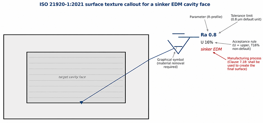
ISO 21920-1:2021 replaced ISO 1302:2002. Clause 5.2 makes three elements mandatory on every callout: graphical symbol, parameter, and tolerance limit. Two more belong on any demanding EDM callout:
- Acceptance rule. The 2021 default is Tmax; the 1302 default was 16%. Reusing legacy 1302 callouts on 21920-1 drawings silently changes acceptance logic.
- Manufacturing process indication. Clause 7.18 lets you require sinker EDM as the final-surface process: “The indicated manufacturing process shall be used to create the final surface.” Without it, the basic symbol permits any process.
Multi-stage surfaces (EDM then polish then coating) use numbered flagnotes per Clause 9.7. Machining allowance is no longer part of the surface symbol (Annex G); place pre-machining stock as a separate dimensional callout.
13. Typical Sinker EDM Applications
Where sinker EDM shows up on real quote sheets:
- Injection mold cavities and inserts, the core of production tooling work.
- Stamping and forging dies with hardened cores.
- Deep-drawing tools and press dies.
- Complex-form aerospace tooling and turbine blade cavities.
- Medical device features where a rotating tool cannot enter.
VDI 3400 Table 6 lists these same applications under Funkenerosives Senken.
14. Sinker EDM RFQ Checklist
Send with your print:
- Feature-level tolerance callouts, not a blanket process spec.
- Surface parameter, tolerance limit, and acceptance rule per ISO 21920-1 Clause 5.2.
- Workpiece material and heat-treat state (H13 HRC 55, Ti-6Al-4V annealed, or the alloy on the drawing).
- Manufacturing process indication if EDM is mandated (Clause 7.18).
- Flushing and venting constraints on blind pockets.
- Post-EDM treatment expectations: stress relief, blast, polish, or coating.
- Inspection method for the surface after machining.
The DFM design guidelines for the drawing package cover the full supplier handoff.
15. FAQ
What does EDM stand for?
Electrical Discharge Machining. VDI 3400 also uses Funkenerosion and Elektroerosion for the German terminology.
Is sinker EDM the same as wire EDM?
No. VDI 3400 splits them into separate branches: Senken (shaped electrode for cavities) and Schneiden mit Draht (moving wire for through-cuts). A blind cavity does not fit wire EDM.
Does EDM cause heat damage?
It thermally alters the top layer. VDI 3402 Blatt 4 §2.2 identifies a white layer and transformation zone; NASA-STD-6016C requires removal on fatigue-critical spaceflight surfaces. On commercial parts, the load case decides.
What is overcut in EDM?
The industry term for the diameter difference between cavity and electrode. VDI 3400 uses side gap (Seitenspalt), with D_recess − D_electrode = 2 × side gap for a circular test recess.
Three checkpoints keep a sinker EDM quote realistic: which VDI class the finish targets, whether the recast layer needs removing, and whether the drawing pins the manufacturing process. When the RFQ answers all three, the supplier has one job instead of three guesses.
To quote a sinker EDM part against the standards above, send the drawing to our end-to-end manufacturing team.
Ready to Quote Your CNC Prototype?
Upload your STEP file and get a DFM review + quote within 12 hours.
No tooling cost. Minimum 1 part.
