

Dewey Wu General Manager & senior mechanical engineer at EPOC CRAFTER, 15 years in design engineering, quality, and metallurgy. Hands-on across CNC machining, metalwork, sheet metal, and prototyping (subtractive + 3D printing).
Die casting forces molten non-ferrous alloy into a steel die under high pressure and delivers a near-net-shape part in one shot. Three alloy families cover most projects: aluminum (A380 leads by volume), zinc (Zamak 3 dominates North America), and magnesium (AZ91D covers the widest range of magnesium applications). This guide covers high-pressure die casting (HPDC), hot chamber vs cold chamber machines, alloy trade-offs, the NADCA 2024 tolerance framework, the four defect categories in ASTM E2973-22, why die-cast housings need CNC finishing, and where giga casting is heading. For sibling processes, our metal casting processes overview places die casting inside the metal-forming family.
1. Die casting in one paragraph
Die casting is a high-pressure metal-forming process where liquid metal fills a hardened steel die, freezes against water-cooled or oil-cooled channels, and gets ejected as a solid part before the cycle restarts. NADCA 2024 defines the loop in six stages: die closes, injection mechanism pushes metal into the cavity, metal fills runner and gate, cooling channels pull heat, die opens, ejector pins push the part free. The numbers below apply to conventional HPDC; VHPDC, squeeze casting, and semi-solid casting fall under NADCA Publication #403. Die casting is non-ferrous only; steel and cast iron do not run here.

2. HPDC vs LPDC and other pressure routes
2.1 High pressure die casting (HPDC)
HPDC is what most engineers and standards mean by die casting without a qualifier. Molten metal enters the cavity at high velocity through the runner and gate, and the injection mechanism holds pressure while the shot freezes. Fictiv cites injection pressures of 1,000 to 20,000 psi (roughly 7 to 138 MPa), which is how HPDC fills 2 to 4 mm walls on aluminum die casting housings with cycles short enough for automotive volume. The trade-off is gas porosity from entrapped air. Conventional HPDC parts are not specified for heat treatment or pressure-tight service without vacuum assist, squeeze, or a switch to VHPDC.
2.2 Low pressure die casting (LPDC)
A sealed furnace sits below the die, and low gas pressure (Fictiv cites 7 to 30 psi) pushes metal up through a riser tube. Fill is slow and laminar, gas entrainment stays low, and LPDC parts take heat treatment better than HPDC parts. LPDC dominates aluminum wheels and larger structural aluminum castings. Parts needing T6 temper and pressure-tight service route to LPDC.
2.3 Gravity, vacuum, squeeze, and semi-solid variants
Gravity die casting (permanent mold) fills under gravity alone with no injection pressure. VHPDC evacuates the die cavity to below 50 mbar (Fictiv), cutting gas porosity enough for structural, heat-treated, and weldable castings. Squeeze casting applies mechanical pressure during solidification to close microshrinkage, covered by ASTM B969/B969M-25 alongside semi-solid metal casting (SSM). SSM has three branches: thixocasting (reheated billet), rheocasting (liquid cooled to semi-solid on transfer), and thixomolding (magnesium chip feedstock in an injection-molding-style machine).
2.4 Which pressure route each alloy family takes
| Alloy family | Route | Why |
| Aluminum (A380, A360, A413) | HPDC cold chamber | Avoids aluminum-gooseneck reaction |
| Zinc (Zamak 3, Zamak 5) | HPDC hot chamber | Low melting point permits injection mechanism in melt |
| ZA-8 | HPDC hot chamber | Only ZA alloy compatible with hot chamber per NADCA 2024 |
| ZA-12, ZA-27 | HPDC cold chamber | Higher aluminum content forces cold chamber |
| Magnesium (AZ91D, AM60B) | HPDC hot or cold chamber | Both routes in commercial use for AZ91D |
| Aluminum wheels, structural Al | LPDC | Density and heat-treatability outweigh cycle time |
| Structural EV components | VHPDC or giga casting | Soundness required for heat treatment and structural load |
3. Hot chamber vs cold chamber
Chamber type sets where the injection mechanism lives relative to the melt. That single choice decides the alloys you can run, the cycle time you hit, and the die casting machine you buy. Both routes are HPDC.
3.1 Hot chamber: gooseneck in the melt
In a hot chamber die casting machine, the injection mechanism (a gooseneck) is submerged in the molten metal pool. The plunger retracts, metal flows into the gooseneck under gravity, then the shot fires and drives metal through the gooseneck and nozzle straight into the die. No ladle transfer; cycle times are the shortest in commercial die casting at single-digit seconds for small zinc components. Cast iron dissolves in molten aluminum on contact, so cast-iron goosenecks cannot run high-aluminum alloys per NADCA 2024. Hot chamber machines run zinc, ZA-8, some magnesium alloys, and lead and tin.
3.2 Cold chamber: shot sleeve loaded from outside
In a cold chamber die casting machine, the shot sleeve sits outside the furnace. A ladle transfers a measured charge into the horizontal shot sleeve, then a plunger fires it into the die. The transfer step adds a fraction of a second to a couple of seconds, so cold chamber cycles run longer than hot chamber cycles. Because the sleeve holds the charge only briefly, a steel sleeve running aluminum does not soak in the melt. Cold chamber is the default for aluminum die casting, copper, and the higher-aluminum ZA alloys ZA-12 and ZA-27.

3.3 Side-by-side
| Attribute | Hot chamber | Cold chamber |
| Injection mechanism | Gooseneck in melt | Shot sleeve outside furnace |
| Metal transfer | None (integrated) | Ladle to shot sleeve |
| Cycle time | Shorter (single-digit seconds for small zinc) | Longer (transfer overhead) |
| Compatible alloys | Zinc, ZA-8, some magnesium, lead, tin | Aluminum, copper, ZA-12, ZA-27, magnesium |
| Injection pressure | Lower end of HPDC range | 2,000 to 20,000 psi (Fictiv) |
Small zinc part: hot chamber. Aluminum part: cold chamber (any quote promising hot chamber aluminum is a red flag). Magnesium part: ask the caster because AZ91D runs on both routes.
4. Alloys used in die casting
NADCA 2024 lists four primary die casting alloy families: aluminum, zinc, magnesium, and zinc-aluminum, with copper and metal-matrix composites as supplementary. Chemistry and mechanical property boundaries sit in ASTM B85/B85M-25 (general HPDC aluminum) and ASTM B969/B969M-25 (squeeze and SSM aluminum); our material properties reference collects the working ranges across grades.
4.1 Aluminum die casting: A380, A360, A383/384, A413
Aluminum die casting alloys carry a density around 2.7 g/cc and account for the largest share of global die castings by volume. A380 is the aluminum die casting workhorse; NADCA 2024 calls it “by far the most widely cast” aluminum die casting alloy, balancing castability, strength, machinability, and corrosion resistance for general-purpose housings, brackets, and enclosures. A360 trades some castability for better corrosion resistance and higher ductility. A383 and A384 handle complex geometries where die filling is the constraint. A413 is the pressure-tightness alloy for parts that must hold pressure without weeping through porosity.
4.2 Zinc die casting: Zamak 3, Zamak 5, ZA-8, ZA-12, ZA-27
The Zamak family (2, 3, 5, 7) sits around 4% aluminum with small magnesium additions and runs hot chamber for the shortest cycle times in commercial die casting. Zamak 3 is the most widely used zinc die casting alloy in North America. Zamak 5 adds copper for higher strength at some cost in dimensional stability. Zamak 7 is a lower-impurity version of Zamak 3 for tighter plating requirements. The ZA family (ZA-8, ZA-12, ZA-27) carries higher aluminum content; ZA-8 is the only ZA alloy compatible with hot chamber per NADCA 2024. Higher ZA numbers give higher strength and better bearing performance at the cost of castability.
4.3 Magnesium die casting: AZ91D, AM60B, AS41B
Magnesium carries a specific gravity around 1.74 g/cc, the lightest structural metal in common commercial use. AZ91D is the most widely used magnesium die casting alloy, with balanced castability, corrosion resistance, and mechanical properties. AM60B, AM50A, and AM20 shift toward higher ductility and impact resistance for automotive steering-wheel armatures and instrument-panel structures. AS41B and AE42 handle elevated-temperature service where AZ91D creep resistance falls short. Note: NADCA 2024 lists Table A-3-10-24 (magnesium alloy chemical composition) as a Standard in the front-of-book index, but the page itself is labeled Guidelines. Pull binding chemistry from the material supplier certified mill test report.
4.4 Copper and metal-matrix composites
Copper die casting sits in a specialized corner because copper high melting temperature attacks conventional gooseneck materials; it appears in electrical applications (rotors, connectors) where conductivity justifies tooling cost. Metal-matrix composites reinforce a base metal with ceramic particles for higher stiffness, wear resistance, or thermal performance, covering a narrow slice of high-value applications.
4.5 A short decision path
Weight critical: magnesium (AZ91D default, AM series for ductility). Pressure-tight or hydraulic: A413 aluminum, or step to LPDC or squeeze casting per ASTM B969. Small high-cycle-count zinc: Zamak 3 on hot chamber. General-purpose housing: A380 aluminum, because supply chain, machining data, finishing processes, and design references are built around it.
5. How to design for die casting (DFM)
NADCA 2024 publishes recommended values for the five DFM features below, flagged as voluntary guidelines that rest on the specific part, alloy, and machine. Our DFM design guidelines for cast and machined features collect the working checklists.
5.1 Draft angles
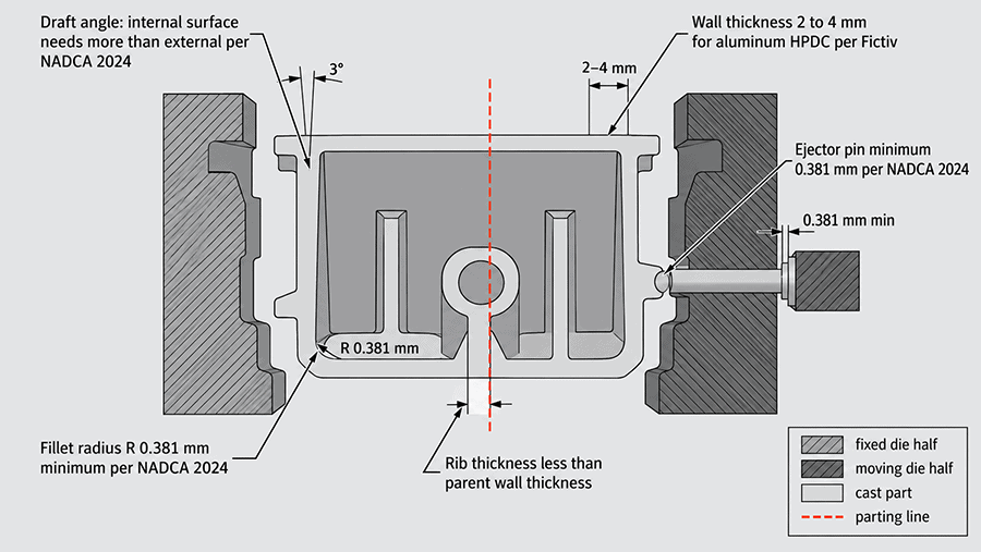
Every surface parallel to die-opening needs draft so the part ejects without dragging. Draft requirements vary with surface type, depth, alloy, and finish. Internal surfaces (cores, pockets, bosses) need more draft than external ones because the casting shrinks onto the core as it cools.
5.2 Wall thickness
Wall thickness is the single most consequential DFM decision on a die casting. Fictiv cites 2 to 4 mm for aluminum HPDC. Uniformity matters more than the absolute number: metal freezes fastest in thin sections and slowest in thick, and the transition concentrates shrinkage porosity. A 6 mm boss sticking out of a 2 mm wall will attract a caster request to core out the boss or split it into ribs.
5.3 Fillets, ribs, and ejector locations
NADCA 2024 gives 0.015 in (0.381 mm) as a minimum for fillet radius, rib thickness, and ejector pin dimensions. Bigger fillets flow better and last longer in the die. Rib thickness sits below parent wall thickness so the rib freezes ahead of the wall. Ejector locations need flat, accessible pads on non-cosmetic, non-sealing faces because ejector marks will always be visible where the pins push.
5.4 Parting line and moving die components
Every feature the die casting mold produces either sits fully in one die half, straddles the parting line, or needs a moving die component (slide or core pull). Place datum references in the same die half whenever function allows. A datum system spanning the parting line and pulling in a moving die component stacks three tolerance contributions. Undercuts drive moving die components; if a small design change moves an undercut into a form the primary die halves can produce directly, that change usually pays for itself.
5.5 DFM feature reference
| Feature | NADCA 2024 minimum | What this means |
| Fillet radius | 0.015 in (0.381 mm) | Floor; local wall thickness is a more useful target |
| Rib thickness | 0.015 in (0.381 mm) | Also thinner than parent wall |
| Ejector pin | 0.015 in (0.381 mm) | Pin diameter and land follow same floor |
| Wall thickness (Al HPDC, Fictiv) | 2 to 4 mm | Alloy, flow length, gate placement move the workable minimum |
| Draft angle | Varies by surface and depth | Internal surfaces need more draft than external |
| Undercuts | Design decision | Add tooling cost, cycle time, tolerance stack |
6. Tolerances die casting can hold
NADCA 2024 publishes tolerance tables in Section 4A with explicit boundaries that decide whether the number applies to your feature. The values are “guidelines only” because actual capability depends on the specific part shape, feature type, and wall-thickness transitions.
6.1 Standard vs Precision
Standard tolerances (S-series) apply to normal production with reasonable die life and standard inspection. Precision tolerances (P-series) require more precise die construction, tighter process control, or additional in-process inspection, and should only be specified on features that need them. Precision tolerances called out on every dimension is usually a design error.
6.2 Linear tolerances, same die half, no moving component
NADCA 2024 S-4A-1-24 and P-4A-1-24 cover the linear tolerance on features formed entirely in one die half without any moving die component.
| Framework | Alloy | First inch (25.4 mm) | Each additional inch |
| S-4A-1-24 Standard | Al, Mg, Zn | ±0.010 in (±0.25 mm) | ±0.001 in (±0.025 mm) |
| S-4A-1-24 Standard | Copper | ±0.014 in (±0.36 mm) | ±0.003 in (±0.076 mm) |
| P-4A-1-24 Precision | Al, Mg, Zn | ±0.002 in (±0.05 mm) | ±0.001 in (±0.025 mm) |
| P-4A-1-24 Precision | Copper | ±0.007 in (±0.18 mm) | ±0.002 in (±0.05 mm) |
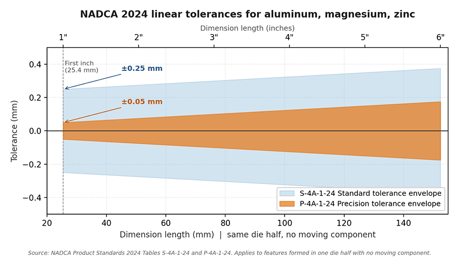
The feature must be formed by one side of the die; a dimension crossing the parting line picks up an additional S-4A-2-24 contribution. A dimension referencing a slide or core pull picks up a moving-die-component contribution.
6.3 Parting line and moving die component stacks
Parting line contribution (S-4A-2-24) varies with projected area and alloy family. NADCA 2024 caps the tabulated values at 300 in² (1935.5 cm²) and directs you to the die caster above that threshold. Moving die component contribution stacks the component positional variability on top of the die-half tolerances. Angularity is not standalone; NADCA handles it as a combination of the base feature tolerance, the parting-line contribution, and the moving-die-component contribution.
EPOC CRAFTER engineering note: when a datum reference crosses the parting line, add the S-4A-2 contribution before you commit to a stack-up. Missing that adder is a common source of first-article inspection surprises on cast parts machined to a datum system across the parting line.
6.4 ISO 8062-3:2023 and machining IT grades
Buyers working from ISO-based drawings see casting tolerances specified against ISO 8062-3:2023 (not NADCA). The standard defines DCTG 1 to 15 (dimensional grades), GCTG 2 to 8 (geometrical grades), and RMAG A to K (required machining allowance grades). A die-cast dimension at DCTG 6 does not have the same absolute tolerance as a machined dimension at IT6; mapping requires reading both tables against the actual dimension size. Our casting tolerance mapping to machined feature IT grades covers the reconciliation.
7. Die casting defects and inspection
ASTM E2973-22 sorts die casting radiographic discontinuities into four categories. Two ground rules: some porosity exists in almost every die casting, so a zero-porosity acceptance criterion is a spec-writing mistake; the categories below apply to conventional HPDC only, not to structural die casting under NADCA #403 or squeeze/SSM under ASTM B969.

7.1 Category A: Porosity
Gas porosity forms when air, hydrogen, or die-lubricant vapor gets entrained during high-velocity injection and cannot escape before freeze. It shows as smooth rounded voids in the sub-surface layer; heating expands the entrained gas and can blister the surface, which is why conventional HPDC parts are not specified for heat treatment. Shrinkage porosity forms when a thick section freezes with no metal path back to the gate, showing as irregular dendritic voids at thermal hot spots. Shrinkage porosity is a design and gating problem, fixed by changing wall thickness distribution, moving the gate, or splitting a thick section into ribs.
7.2 Categories B, C, and D
Cold shut happens when two metal fronts meet after cooling below fusion temperature and fail to weld; a visible seam appears at flow convergence. Misrun happens when metal freezes before reaching a feature. Both point at metal or die temperature too low, fill velocity too slow, or a gate placed so metal travels farther than alloy fluidity allows.
Shrinkage cavities are large voids in thick sections indicating a gating or wall thickness problem. Shrinkage cracks (hot tears) form when a thin section between two thicker regions gets pulled apart by differential contraction, showing as fine cracks along the parting line or wall thickness transitions.
Inclusions are non-metallic material embedded in the casting: die lubricant residue, oxide skins, refractory particles, or slag past the skimming step. Prevention lives at melt-management and lubricant-application steps.
7.3 Inspection routes: method by defect
| Defect category | Primary method | Reference | What it shows |
| A. Gas porosity | Radiography (X-ray) | ASTM E505-22 | Rounded voids through casting |
| A. Shrinkage porosity | Radiography | ASTM E505-22 | Dendritic voids at hot spots |
| A. Sub-surface porosity | Industrial CT | ISO 15708-2/3:2025 | Full 3D void distribution |
| B. Cold shut | Visual, dye penetrant | Internal | Surface line at flow convergence |
| B. Misrun | Visual | Internal | Missing or partial features |
| C. Shrinkage cavity | Radiography | ASTM E505-22 | Large voids in thick sections |
| C. Shrinkage crack | Dye penetrant + radiography | Internal | Fine cracks at wall transitions |
| D. Inclusion | Radiography | ASTM E505-22 | Density variations vs surrounding metal |
| Geometric | CMM per ISO 1101:2017 | ISO 1101:2017 | Feature-to-datum conformance |
| Full dimensional | ISO 8062-3 DCTG check | ISO 8062-3:2023 | Dimension vs specified grade |
ASTM E505-22 is the reference film radiograph atlas for die-cast aluminum and magnesium, defining Level 1 through Level 4 severity (Level 1 tightest). Specify the level the function needs, not the tightest; tighter levels raise scrap rates and inspection time. Industrial CT per ISO 15708-2:2025 and ISO 15708-3:2025 gives 3D defect mapping for first-article validation, structural parts, and failure analysis, not for production inspection.
Three procurement rules: specify by category, not by “no porosity” (a blanket “sound casting” is not enforceable); match inspection to the defect that matters for function; distinguish design-driven defects (Category A shrinkage, Category C) from process-driven (Category A gas, Category D). If shrinkage keeps failing inspection, change the design, not the process spec.
8. Why die castings usually need CNC machining
Most die-cast housings, brackets, and structural parts go through a CNC operation after casting for four reasons: features casting cannot hold to required tolerance, features casting cannot produce at all, sealing and mating surfaces, and machined datum references. Our 5-axis CNC machining services for as-cast housings run the finishing route on aluminum die-cast parts destined for anodizing.
8.1 Skin depth: the 0.38 to 0.50 mm rule
NADCA 2024 identifies a skin layer on HPDC parts running 0.015 to 0.020 in (0.38 to 0.50 mm) deep from the as-cast surface. That skin froze first against the die wall and is denser than the material below. Cut deeper than the skin on a critical surface and you expose the sub-surface material where Category A gas porosity concentrates: pits on the machined face, leak paths, failed acceptance. Keep critical machined surfaces within skin depth, or add wall thickness so skin plus machining stock plus safety margin stays above the porosity zone.
8.2 Machining stock allowance
NADCA 2024 gives a normal minimum machining stock of 0.010 in (0.25 mm), a floor, not a target. Practical stock runs higher because casting-to-casting variation eats into stock, fixture locating adds to the stack, and distortion during aging or heat treatment shifts dimensions between casting and machining. A working number for aluminum HPDC is 0.5 to 1.0 mm on critical surfaces. ISO 8062-3:2023 handles the same decision through RMAG grades A to K.
8.3 Datum transfer, sealing surfaces, and threads
Cast surfaces are not repeatable enough to serve as finished-part datums when finished tolerances are tighter than the base casting tolerance. Machine three datum surfaces first, then measure everything else against them. Sealing surfaces (O-ring grooves, gasket faces) need flatness and finish tighter than casting can hold: Ra 1.6 μm or better and flatness in the 0.02 to 0.05 mm range depending on seal type. Threaded features are almost always machined after casting; cast-in threads have inconsistent form and reduced load capacity. For anodizing on aluminum or passivation on corrosion-critical parts, our anodizing and surface finishing capabilities run the sequence rough machine, semi-finish, finish machine, anodize, final inspection.
9. Where die casting shows up in real products
9.1 Automotive die casting
Powertrain components (transmission cases, cylinder heads on some engine families, oil pans, valve covers) run aluminum die casting because weight reduction over cast iron pays back across the vehicle life. Structural components (crossmembers, shock towers, engine cradles) and EV battery housings run VHPDC or squeeze casting where mechanical property targets require it. EV battery housings are a fast-growing category with design review lead times of 6 to 12 months from first CAD to first part. Our automotive component manufacturing covers the wider automotive process routing.
9.2 Consumer electronics
Laptop and tablet chassis use magnesium die casting where weight matters most (AZ91D dominates thin-and-light lines) and aluminum where cost matters more. Connector housings, camera housings, and heat-sink assemblies use aluminum for the thermal conductivity payoff. EMI and RFI shielding enclosures use zinc die casting (Zamak 3 primarily).
9.3 Industrial and medical die casting
Pumps and valves use aluminum die casting where A413 pressure-tightness over A380 pays back; hydraulic manifolds, pump bodies, and valve housings routinely specify X-ray inspection per ASTM E505 with tight acceptance levels. Instrument housings use A380 for cost or A360 for corrosion in humid environments. Medical device housings appear in imaging equipment, patient monitoring hardware, and larger surgical instrument bodies, with regulatory requirements on material traceability and cleanability on top of the base casting decisions.
9.4 When to look at a different process
Ferrous parts (steel, stainless, cast iron) do not run in die casting. Below roughly 1,000 to 5,000 parts per year, tooling amortization usually does not close and sand casting, investment casting, or machining from wrought stock wins. Parts requiring tolerances tighter than P-4A-1 can hold, or surface finish better than as-cast, will need machining anyway. Parts requiring heat treatment or pressure-tight service belong in LPDC, VHPDC, squeeze casting, or SSM territory.
10. Giga casting, VHPDC, and where die casting is heading
10.1 Giga and mega casting

Giga casting (or mega casting) refers to single-piece aluminum die castings large enough to replace multi-component welded assemblies. Tesla Model Y front and rear underbody castings are the reference examples, produced on Idra Group presses in the 6,000 to 9,000-tonne clamping-force range. Volvo, Xpeng, Nio, and other manufacturers have brought giga-cast structural components into production. Replacing 70 or 80 stamped-and-welded steel components with a single aluminum casting removes assembly stations, welding operations, and fixture complexity, and reduces total body-in-white weight. Mega presses cost tens of millions of dollars, and structural casting dies cost single-digit to low double-digit millions.
10.2 The volume threshold
Public analysis by Roland Berger and other automotive industry researchers puts the break-even for structural giga castings in the 250,000 to 350,000 vehicles per year range for a specific platform. Below that volume, a mega press dedicated to one platform sits underused, which is why giga casting stays concentrated in high-volume EV programs.
10.3 VHPDC and heat-treatment-free alloys
VHPDC evacuates the die cavity to below 50 mbar (Fictiv), cutting entrained gas porosity so parts take T6 or T7 heat treatment, delivering mechanical properties conventional HPDC cannot approach. Squeeze casting and SSM are the other high-integrity branches per NADCA #403 and ASTM B969/B969M-25. Heat-treatment-free aluminum alloys formulated for structural HPDC let manufacturers skip the heat-treatment step on large parts where distortion management would otherwise dominate cost.
10.4 What this means for smaller programs
Alloy development for structural HPDC produces new grades usable at conventional part sizes, and vacuum-assist process control from VHPDC is becoming more available on standard HPDC machines. For programs evaluating casting, machining, finishing, and assembly as an integrated decision instead of separate quotes, our end-to-end manufacturing coordination covers the trade-offs.
11.Where to take this next
Three decisions cover most die casting routing questions. Aluminum general-purpose part: A380 on a cold chamber HPDC machine, plan a CNC finishing operation on datum and sealing surfaces. Part needing heat treatment, pressure-tight service, or structural mechanical properties: route to LPDC, VHPDC, or squeeze casting per ASTM B969 and NADCA Publication #403. Small zinc part in high volume: hot chamber machine with Zamak 3. Send your STEP file and drawing for a DFM review on the casting-plus-machining route for your specific part.
12.FAQ
What is the difference between HPDC and LPDC?
HPDC injects molten metal at 1,000 to 20,000 psi (Fictiv), fills thin walls, and runs short cycles at the cost of higher gas porosity. LPDC uses a sealed furnace below the die pushing metal up through a riser tube at 7 to 30 psi, giving denser castings that take heat treatment at longer cycle times. HPDC dominates general-purpose aluminum and zinc housings; LPDC dominates aluminum wheels and larger structural aluminum parts where soundness matters more than cycle time.
Which aluminum die casting alloy should I specify?
A380 is the starting point for general-purpose aluminum die casting per NADCA 2024, which calls it the most widely cast aluminum die casting alloy. Move to A360 when corrosion resistance or elevated-temperature strength matters more than castability. Move to A383 or A384 for complex geometries where die filling is the constraint. Move to A413 when the part has to hold pressure without weeping through porosity. Chemical composition boundaries are in ASTM B85/B85M-25.
Do die castings always need CNC machining after casting?
Most functional die-cast parts do. Sealing surfaces need flatness and finish tighter than casting can hold, mating surfaces need positional tolerance carried by machined datums, threaded features perform better machined into cast bosses than cast in place, and finished-part datum systems need machined references. Cosmetic or non-critical parts sometimes ship with only trim and deflash. Design the part expecting a CNC step; skipping it is the exception.
What tolerance can die casting hold?
NADCA 2024 S-4A-1-24 gives ±0.010 in (±0.25 mm) on the first inch and ±0.001 in (±0.025 mm) on each additional inch for aluminum, magnesium, and zinc dimensions formed in the same die half with no moving die component. Precision tolerance P-4A-1-24 tightens the first-inch value to ±0.002 in (±0.05 mm). Dimensions crossing the parting line or involving moving die components pick up additional contributions from S-4A-2 or the moving-die-component tables. For tolerances tighter than P-4A-1, plan a CNC operation on that feature.
Ready to Quote Your CNC Prototype?
Upload your STEP file and get a DFM review + quote within 12 hours.
No tooling cost. Minimum 1 part.
