

Dewey Wu General Manager & senior mechanical engineer at EPOC CRAFTER, 15 years in design engineering, quality, and metallurgy. Hands-on across CNC machining, metalwork, sheet metal, and prototyping (subtractive + 3D printing).
A bevel and a chamfer both replace a sharp edge with an angled surface, but the name does not define the geometry. If you are asking what is a bevel or what is a chamfer for a drawing or RFQ, the practical answer is to control the dimensions that matter to function. A beveled edge, a chamfered edge, an ISO 13715 edge break, and a welding bevel can look similar while carrying different requirements. ISO 129-1:2018 requires dimensions sufficient to define nominal geometry unambiguously. ISO 13715:2017 covers undefined edges. ISO 9692-1:2013 places a weld bevel inside a complete joint preparation. Those boundaries drive machining, cost, and inspection.
1. Bevel vs Chamfer: What Actually Changes on the Drawing?
The difference between bevel and chamfer is useful language, not a universal size rule. In shop usage, chamfer often means a small chamfer edge for burr removal, assembly lead in, a chamfered hole, or a thread entry. Bevel often describes a broader or more functionally important bevel edge. Neither ISO 129-1 nor the supplied standards define chamfer vs bevel by a fixed width or by saying that one must be 45 degrees.
A 45 degree chamfer is common, but a chamfer angle can be another value. The same is true for a bevel angle. The drawing should identify the controlled linear characteristic and angle, or another equivalent geometry. For a shaft, axial length, radial depth, sloped face length, and angle are different characteristics. A bevel and chamfer can therefore look alike while inspection targets different dimensions.
The practical bevel meaning and chamfer meaning are function plus specification. That is also the safest bevel definition and chamfer definition for procurement: the supplier needs enough information to make and verify the feature without guessing. A label such as “bevel” or “chamfer” is not an acceptance criterion.
| Feature | Use it when | Control on drawing | Do not assume |
| Defined chamfer | A specific angled edge is functional | Linear size and angle, two linear dimensions, or another unambiguous definition | 45 degrees unless stated |
| Defined bevel | The angled face or its endpoints matter to fit, access, contact, or fabrication | Bevel dimension, bevel angle, endpoints, or profile as required | That a larger chamfer is automatically a bevel |
| Undefined edge | Only permitted material excess or removal matters | Applicable ISO 13715 indication and scope | A fixed planar chamfer |
| Weld bevel | The edge is part of a welding joint preparation | Joint geometry from the drawing, welding procedure specification (WPS), and applicable preparation requirements | That one angle defines the complete joint |
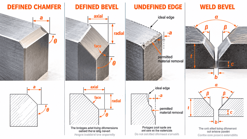
2. Chamfer Callout, Bevel Callout and Dimensioning
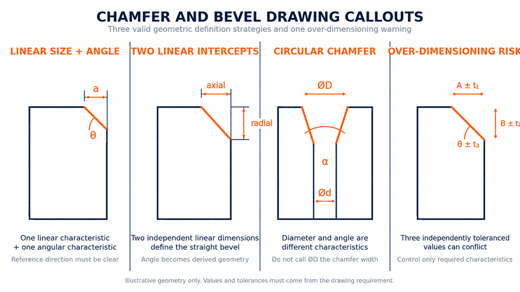
A chamfer callout or bevel callout should let manufacturing reconstruct the intended nominal geometry and let inspection identify the controlled characteristic. ISO 129-1:2018, Clause 4.1.1, states that only the dimensions necessary to define nominal geometry unambiguously shall be presented. The same standard also warns against using the same dimension more than once for a feature.
For the broader tolerance hierarchy, title block rules, and GD&T context, use EPOC CRAFTER’s CNC drawing tolerance callouts. This article stays with chamfer dimensioning and bevel dimensioning.
2.1 How to Dimension a Chamfer or Bevel
One common chamfer notation is a linear size plus a chamfer angle, such as 2 mm × 30 degrees, provided the drawing makes clear where the 2 mm is measured and what establishes the angle. A second method uses two linear intercepts, which can leave the angle as a derived value. ISO 129-1 also shows a circular chamfer described by diameter and angle. A chamfer dimension is therefore not automatically the sloped face length.
For a feature whose angle is not 45 degrees, avoid a chamfer symbol or bevel symbol that leaves the reference direction unclear. The same caution applies to bevel notation. If two linear dimensions already define the endpoints, adding an independent angle with its own tolerance can over constrain the feature. Chamfer tolerance and bevel tolerance should be assigned only to characteristics that function actually needs.
A useful rule for how to call out a chamfer is to choose the smallest independent set of dimensions that controls the function. For a circular hole entry, that may be diameter plus angle. For a shaft chamfer, axial setback plus angle may be more useful. For a sealing or mating bevel, two endpoints may communicate function better than a nominal face width.
When one edge genuinely needs tighter control than surrounding features, the tight tolerance CNC features guide explains when an individual requirement is justified and when a broader default remains appropriate.
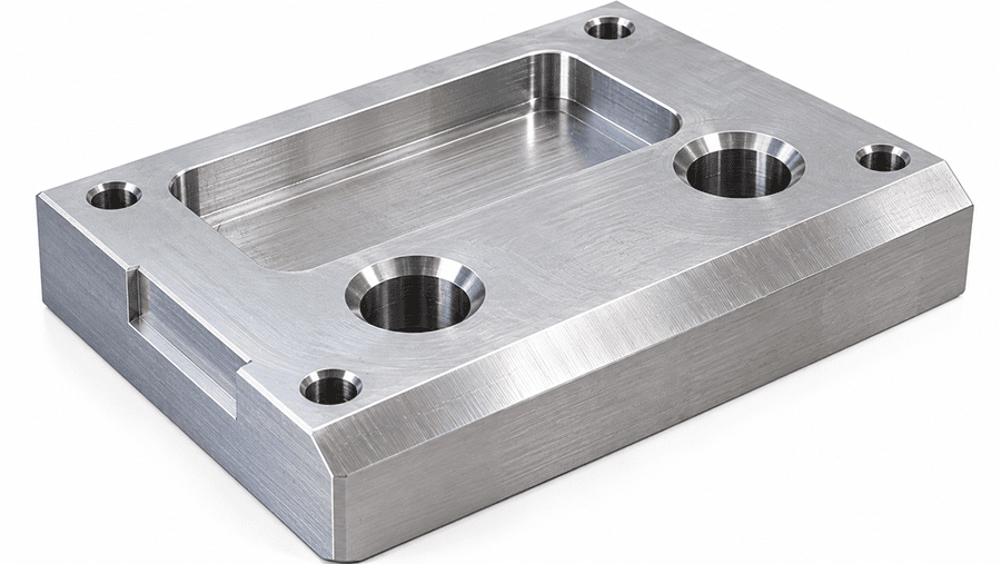
3. Edge Break vs Chamfer: Defined and Undefined Edges
Edge break vs chamfer is a specification boundary, not a cosmetic distinction. ISO 13715:2017 controls permitted deviation of an undefined edge from the ideal geometry. A value for material removal does not become a fixed 45 degree chamfer. That is why chamfer vs edge break and edge break vs chamfer should be resolved before RFQ release.
A note such as “break all sharp edges” or “break sharp edges” can be adequate only when the organization has a controlled interpretation and the exact profile is not functional. An edge break callout should not replace a defined chamfer when a seal, lead in, fit, contact surface, or measurement depends on a specific plane or angle. An edge break drawing can still contain local exceptions where a particular edge needs defined geometry.
Legacy ISO 2768 users should separate historical broken edge tolerances from current undefined edge practice. EPOC CRAFTER’s ISO 2768 edge break changes guide covers that migration without turning ISO 13715 into a chamfer tolerance table.
Use undefined edge control when the exact profile does not matter. Use a defined chamfer or bevel when function depends on geometry. That decision also sets the inspection burden: edge inspection may confirm permitted excess or removal, while a defined machined edge may require size, angle, or profile measurement.
4. Bevel Machining and CNC Chamfer Methods
Bevel machining and chamfer machining are driven by access, geometry, material, setup orientation, quantity, and inspection. The drawing should define the result, not prescribe a cutter without a contractual reason. A CNC bevel on an accessible external edge may be a simple milling path. The same bevel cut on the back of a pocket may require reorientation, a special tool, or multi axis access.
Chamfer milling works well when the required geometry matches a suitable cutter and the edge is accessible. Bevel milling may use a dedicated angled cutter, an end mill with a programmed path, or a multi axis strategy. The beveling process changes as the face becomes wider because material removal, engagement, heat, tool load, and cycle time increase. No universal feed or speed is defensible without the material, tool geometry, coating, machine condition, and engagement.
Turning is usually efficient for a shaft chamfer, thread chamfer, pipe bevel, or rotational edge bevel because the feature can remain referenced to the same axis as adjacent diameters. A hole chamfer or chamfered hole may be created during milling, drilling related operations, or turning. The drawing still decides whether the feature is only edge finishing or a controlled lead in.
For tool access, setup count, and manufacturability tradeoffs, the CNC DFM design guidelines give the broader design context. When the geometry is ready to quote, EPOC CRAFTER’s CNC bevel machining services page shows the available CNC process routes.
The same rule applies to metal beveling, steel beveling, plate beveling, and pipe beveling: how to make a bevel depends on access and process context, not on the word bevel. A feature that is easy in one setup can become expensive when a fixture or wall blocks the cutter.
5. Welding Bevel and Weld Prep
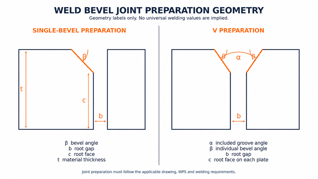
A welding bevel is part of a welding joint preparation, not simply a larger chamfer. ISO 9692-1:2013 covers steel joint preparation for specified welding processes and distinguishes the bevel angle of one prepared face from the included groove angle. It also treats root face, root gap, thickness, welding side, backing, and process as part of the preparation context.
For a bevel groove weld, the weld bevel angle and groove angle are not interchangeable. Root gap is the separation between parts at the root, while root face is the remaining land at the prepared edge. A single bevel weld, single bevel groove, double bevel weld, and double bevel groove therefore carry more geometry than an ordinary edge chamfer. V, U, and J preparations add other joint profiles.
ISO 9692-1 provides recommended joint preparations tied to joint type, material thickness, geometry, and welding process. It does not create one universal steel bevel angle. Weld prep, weld preparation, weld joint preparation, and welding joint preparation should therefore be read with the actual drawing and WPS. The same applies to a weld groove made by machining, grinding, or cutting.
This boundary also keeps ordinary machining language clean. A local chamfer may exist on a component that also has a weld bevel. Calling both features the same thing can confuse quoting and inspection.
6. Bevel Inspection and Chamfer Inspection
Bevel inspection and chamfer inspection should start from the controlled characteristic. A bevel gauge or chamfer gauge is useful only when its measurement principle matches the drawing. Chamfer measurement may target an opening diameter, a linear leg, or an angle. Bevel measurement may target endpoints, angle, or profile. A gauge name does not guarantee that it measures the required characteristic.
For how to measure a chamfer or how to measure a bevel, select the instrument after identifying the drawing requirement, tolerance, access, and uncertainty. Optical systems can evaluate visible profiles. A CMM can evaluate coordinates, surfaces, and datum relationships when probing access is suitable. Bevel angle measurement may use a different method from face width or endpoint measurement.
ISO 17637:2016 provides a different inspection layer for welds. It can be applied to visual testing of the joint before welding and requires, where applicable, that the shape and dimensions of the weld preparation meet the WPS. It does not select the bevel angle, root face, or root gap. Those values come from the controlling WPS, drawing, preparation standard, or project requirement.
Where a bevel or chamfer is a CTQ feature, EPOC CRAFTER’s tolerances and GD&T standards resource helps separate size, geometry, and inspection requirements instead of treating one tolerance as a universal control.
| Inspection case | Requirement source | Verify | Decision boundary |
| Defined chamfer | Drawing | Chamfer dimension, angle, diameter, or other stated characteristic | Do not inspect an unstated derived value as a separate requirement |
| Undefined edge | Drawing plus applicable ISO 13715 indication | Permitted edge deviation or condition | Do not convert the requirement into a fixed chamfer |
| Weld bevel | Drawing, WPS, and applicable joint preparation requirement | Specified bevel or groove geometry and fit up | Do not invent a universal angle or root gap |
| Dedicated gauge | Drawing plus instrument capability | The characteristic that the gauge actually measures | Confirm gauge angle, range, calibration, and relationship to the callout |
7. RFQ Checklist
Before release, confirm the edge function, feature type, independent dimensions, angle reference, tolerance, final surface condition, process context, and inspection characteristic. A drawing should tell the supplier what must be accepted without dictating a machine route that the product does not require.
| RFQ check | Confirm | Release decision |
| Function | Deburr, lead in, fit, seal, contact, clearance, or weld preparation | If function depends on geometry, use a defined feature rather than a vague edge note |
| Geometry | Linear size, angle, diameter, endpoints, or profile | Use the minimum independent dimensions needed to define the feature |
| Tolerance | Only characteristics that affect acceptance | Avoid over constraining derived geometry |
| Final condition | As machined or after finishing | State the acceptance state when coating or polishing can change the edge |
| Inspection | Characteristic, method capability, and access | Make the requirement measurable before quoting |
This checklist consolidates the article’s standard based drawing rules and manufacturing decision points. It does not assign process capability or inspection accuracy without project specific evidence.
When coating or another post process can alter a functional edge, the surface finishing dimensional changes page provides the process context for masking, coating buildup, and final state acceptance.
For a normal CNC part, send the CAD model, controlled drawing, material and condition, edge geometry, tolerances, final surface condition, quantity, and CTQ inspection requirements. For a weld bevel, add the applicable WPS and joint preparation information. The supplier should not have to infer a functional edge from a rendering.
8. FAQ
8.1 What Is the Difference Between Bevel and Chamfer?
The practical difference is usage and function, not a universal angle or width threshold. A chamfer often describes a small edge treatment. A bevel often describes a larger or more functional angled face. For acceptance, use the drawing geometry rather than the label.
8.2 How to Dimension a Chamfer That Is Not 45 Degrees?
Use one linear dimension plus the angle, or two independent linear dimensions, provided the drawing makes the reference direction and controlled characteristic unambiguous. Do not rely on a familiar 45 degree convention for a feature whose angle is not 45 degrees.
8.3 How to Measure a Chamfer and Choose a Chamfer Gauge?
Match the gauge to the characteristic and angle range on the drawing. A chamfer gauge may indicate a diameter or another gauge specific value. Verify what the tool measures before using it for acceptance. Optical or coordinate methods may be more suitable for profile or endpoint control.
8.4 Can a Chamfer Mill Make a Larger Bevel Cut?
Sometimes, but tool access, cutter geometry, machine rigidity, material, bevel width, and engagement decide whether it is sensible. A larger bevel may need multiple passes, another cutter, a programmed milling path, or a different setup. There is no universal depth of cut without the actual tool and process conditions.
For release, keep one test in front of the drawing: can the supplier make the edge and can inspection accept it without guessing? Define the geometry when function depends on it. Use undefined edge control when exact shape does not matter. Treat a weld bevel as joint preparation, not as a large chamfer.
Ready to Quote Your CNC Prototype?
Upload your STEP file and get a DFM review + quote within 12 hours.
No tooling cost. Minimum 1 part.
