

Dewey Wu General Manager & senior mechanical engineer at EPOC CRAFTER, 15 years in design engineering, quality, and metallurgy. Hands-on across CNC machining, metalwork, sheet metal, and prototyping (subtractive + 3D printing).
G-codes and M-codes sit on top of a much larger chain that decides whether a CNC part meets your drawing. G-code drives axis motion. M-code triggers spindle, coolant, and tool change. Neither guarantees a conforming feature. The finished part depends on the coordinate chain from CAD datum through work offset to tool offset, the post-processor that translates the CAM toolpath for your specific controller, and a verification chain from CAM simulation through first article inspection.
This guide covers where ISO 6983-1:2009 draws its boundaries, how G54-G59 work offsets and G43 tool length compensation behave across FANUC, Haas, Siemens, and Heidenhain, why post-processor mismatches produce collision-free simulations but rejected parts, and what a procurement owner should audit before releasing an NC program.
1. What G-Code and M-Code Do on a CNC Machine
G-codes and M-codes are the two address-word groups defined by ISO 6983-1:2009. CNC G-code drives geometry and motion. CNC M-code drives machine state. Together they form what shops call CNC programming codes: the instructions that move axes and switch hardware on the same block.
1.1 G-code: geometry and motion
A G-code motion block needs a coordinate mode (G90 absolute or G91 incremental), a plane (G17/G18/G19), a feed on F, an interpolation type, and axis targets. G00 rapid-positions, G01 cuts linearly, G02/G03 run circular interpolation. Most G-codes are modal: G01 stays active until G00/G02/G03 cancels it; G54 stays active until another work offset call replaces it. ISO 6983-1 organizes G-codes into three modal categories (FRC, TBO, DDFC) but leaves the assignment of each code to the machine builder, which is why a FANUC 0i-MF and a Haas VF-2SS can group G43 differently and both remain standard-compliant.
1.2 M-code: machine state
M-code triggers spindle direction (M03/M04/M05), tool change (M06), coolant (M08/M09), program end (M30), and controller subroutines. ISO 6983-1 defines M00 through M30. Everything above M30 is machine-specific. Two M-codes on the same block execute in an implementation-defined order. Read the specific controller manual, not the general reference.
1.3 Where ISO 6983-1:2009 draws the line
The standard covers program-data syntax, address words, and modal handling. It does not define kinematics, does not specify how a controller stores tool offsets, and does not assign the H address (used with G43) or the O address (program number on FANUC). Both are machine-builder additions, not standard-mandated.
The RESET state on a fresh session is not standardized either, which is why the safe-start block G17 G20 G40 G49 G80 G90 sits at the top of most production programs. It forces a known modal state before the first cut. Skipping it is a common cause of first-run scrap when programs move across controllers.
2. Reading a Real CNC Program Line by Line
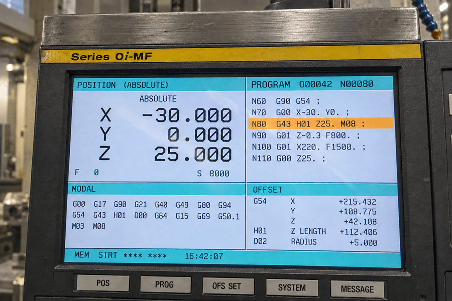
Reading a real CNC program is faster than reading its specification. G-code programming exposes the coordinate and offset chain a written spec hides. This section walks through a compact 3-axis milling program for a 6061-T6 bracket on a Haas VF-2SS with the Haas Next Generation Control, using G54 as the work offset and calling tool length compensation with G43.
2.1 A production 3-axis milling program, annotated
%
O00042 (BRACKET-6061-FACE-POCKET)
(TOOL 1: 50MM FACE MILL)
(TOOL 2: 10MM 4-FLUTE END MILL)
N10 G17 G21 G40 G49 G80 G90 (SAFE-START)
N20 G91 G28 Z0. (RAPID Z TO HOME)
N30 G91 G28 X0. Y0. (RAPID X/Y HOME)
N40 T01 M06 (LOAD TOOL 1)
N50 S8000 M03 (SPINDLE ON CW, 8000 RPM)
N60 G90 G54 (ABSOLUTE, WORK OFFSET G54)
N70 G00 X-30. Y0. (RAPID TO START)
N80 G43 H01 Z25. M08 (Z RAPID WITH H01, COOLANT ON)
N90 G01 Z-0.3 F800. (FEED DOWN 0.3 MM AT 800 MM/MIN)
N100 G01 X220. F1500. (FACE MILL AT 1500 MM/MIN)
N110 G00 Z25. (RAPID RETRACT)
N120 M09 (COOLANT OFF)
N130 G91 G28 Z0. (Z HOME)
N140 T02 M06 (LOAD TOOL 2)
N150 S6500 M03 (SPINDLE ON, 6500 RPM)
N160 G90 G54 (ABSOLUTE, G54 REAFFIRMED)
N170 G00 X40. Y30. (RAPID TO POCKET START)
N180 G43 H02 Z25. M08 (Z RAPID WITH H02, COOLANT ON)
N190 G01 Z-5. F600. (FEED TO POCKET DEPTH)
N200 G41 D02 X50. Y30. F900. (CUTTER COMP LEFT, LEAD-IN)
N210 G01 X50. Y50.
N220 G01 X30. Y50.
N230 G01 X30. Y30.
N240 G01 X50. Y30. (CLOSE CONTOUR)
N250 G40 G01 X60. Y30. (CANCEL CUTTER COMP)
N260 G00 Z25.
N270 M09
N280 M05
N290 G91 G28 Z0.
N300 G91 G28 X0. Y0.
N310 M30 (PROGRAM END)
%
Where the risk lives:
- N10 safe-start forces modal state before the first move. If the previous program ended in G91 incremental, the first G00 would move to a relative coordinate.
- N60 / N70 set G90 absolute and G54 (both modal, stay active until replaced) then rapid to start. Wrong G54 sends N70 to the wrong coordinate and the controller cannot detect this.
- N80 / N100 activate H01 tool length compensation and set feed F1500. Without an explicit F change, the cutter would face-mill at F800, the last modal feed.
- N200 / N310 turn on cutter compensation with G41 D02 (activation on a curve, inside a corner, or with a lead-in shorter than the cutter radius will gouge) and program end M30 does not reset G54, H01, or any modal state.
The same skeleton scales to the multi-tool jobs run through our rapid CNC prototyping workflow and small production lots.
2.2 The safe-start block and modal categories
The safe-start block forces six modal states: XY plane (G17), metric units (G21), cutter compensation cancel (G40), tool length cancel (G49), canned cycle cancel (G80), and absolute mode (G90). Each is a state the previous program could have left in a different position, and each is a category where ISO 6983-1:2009 leaves the RESET behavior to the machine builder. On a FANUC 0i-MF the RESET parameter is programmable and can be set differently on two nominally identical machines. On a Haas NGC, RESET returns to a documented state that changes with parameter settings.
ISO 6983-1 defines three modal categories. FRC codes stay active until replaced (G00, G01, G02, G03 are FRC on every mainstream controller). TBO codes cover plane selection, coordinate mode, and unit selection. DDFC codes are one-shot; G04 dwell and G28 reference return behave that way. Whether G43 tool length compensation is modal or one-shot depends on the machine builder. Read the specific controller’s modal group table before writing the safe-start block.
3. The Coordinate Chain: Machine, Work, Fixture, Part, Tool
Every CNC part sits on a chain of coordinate references that starts on the CAD model and ends on the machined feature. A correct G-code program with a wrong link on that chain produces a rejected part.
3.1 Machine coordinate versus work coordinate
The machine coordinate system (MCS) is fixed by the machine builder; its origin sits at a physical position defined by home switches or absolute encoders. G53 addresses the MCS directly and ignores every active work offset. The work coordinate system (WCS), also called the workpiece coordinate system, is a translation of the MCS to a location convenient for programming the part. G54 through G59 are the six standard WCS registers on FANUC, Haas, and Siemens. When you call G54, the controller adds the G54 X, Y, Z values to every subsequent commanded position until another WCS is called. G54 has no fixed physical location until you assign one.
The chain runs: CAD datum (the drawing’s GD&T A/B/C datums) → CAM WCS → Fixture datum (physical reference on the table) → G54 work offset (machine value that shifts commanded coordinates onto the CAM WCS) → Tool offset (H register, tool tip to spindle gauge line) → Actual feature on the part.
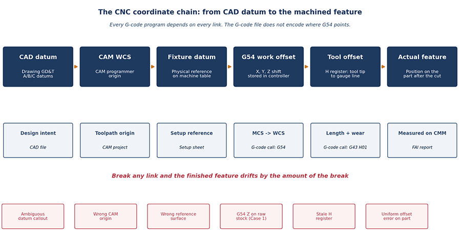
Break any link and the feature drifts by that amount. The G-code file does not encode where G54 points; that lives in the controller and is re-entered on every setup. Reading the drawing against the GD&T tolerances and inspection standards catches ambiguous datum callouts before they reach the machine. The DFM design guidelines upstream catch datum choices that force a setup to touch off on a surface that will not exist after the first cut.
3.2 G54 through G59 are zero shifts, not setup procedures
ISO 6983-1:2009 defines G54 through G59 as work coordinate system offsets. It does not specify how the operator sets them or what reference surface the offset uses. Two setups that both call G54 can produce parts of different height when the offset is set to different references. If the setup starts with a facing operation that removes 0.30 mm of stock, the finished datum only exists after that first cut. Touching off G54 Z on raw stock before facing locks in a 0.30 mm error that propagates through every downstream depth.
3.3 How a wrong offset produces a rejected part with a correct program
Case 1 (EPOC CRAFTER shop-floor data). 6061-T6 aluminum optical-sensor enclosure, 180 × 120 × 42 mm, 25-piece lot. Haas VF-2SS, Haas NGC software 100.23.000.1200. NC file posted from Mastercam 2024 Update 2 through EC-HVF2SS-3X rev 7.3.
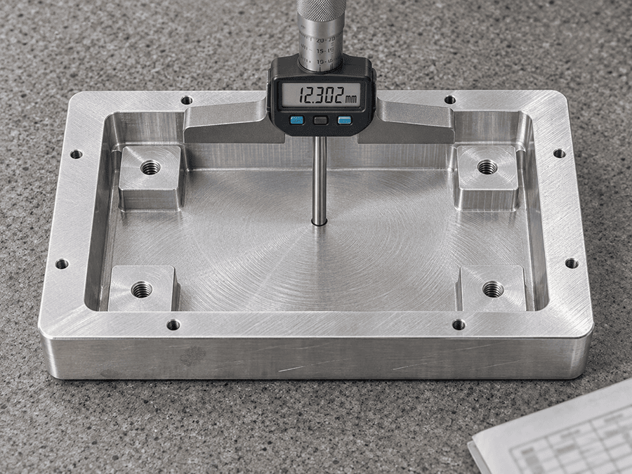
First article off the CMM (calibrated 2026-05-18) came out uniformly 0.30 mm off on the pocket floor and four internal mounting pads. Drawing: pocket depth 12.00 ±0.05 mm from datum A, pad height 6.00 ±0.05 mm. Measured pocket depth: 12.302, 12.298, 12.305, 12.301 mm. Measured pad height: 5.697 to 5.704 mm.
Root cause: the setup sheet said “Z0 top face” without naming the finished datum. The operator touched off G54 Z on raw stock before the 0.30 mm facing cut. Tool length offset H01 was correct. The NC file was correct. G54 X and Y were correct. Only the Z reference sat on a surface that no longer existed after facing.
Fix: reset G54 Z on datum A after facing; added a probing cycle; setup sheet revised to name datum A and the probing stage (revision C2). Replacement first article measured 12.008-12.019 mm pocket depth and 5.991-6.006 mm pad height. All 24 remaining parts passed. The NC file was never touched.
4. Tool Length and Cutter Compensation
Tool compensation is the layer between the programmed centerline and the real cutting edge. Two families run in parallel: tool length compensation on Z (G43 with H) and cutter compensation on XY (G41 and G42 with D). Both are stored in the controller. Neither carries a check that the value matches the tool physically in the spindle.
4.1 Why G43 with the wrong H number scraps the part
G43 activates tool length compensation using the value in the H register named on the block. G43 H01 Z50. tells the controller: move Z to 50, then apply H01 as a Z offset. G44 applies it negative; G49 cancels. The H address is not defined by ISO 6983-1:2009. A tool loaded in position 1 does not automatically use H01. Swapping tools between machines requires re-entering the length in the correct register.
Wrong H produces a uniform Z offset across every feature the tool cuts. If H01 is 0.15 mm long compared with the tool physically in the spindle, every Z depth cut by tool 1 runs 0.15 mm shallow. The G-code did not fail. The register did.
4.2 Cutter compensation G41 and G42: lead-in rules
G41 shifts the tool path left of the programmed direction, G42 shifts right, and G40 cancels. Neither can activate on a curved move. They require a linear lead-in of at least the tool radius so the controller has room to establish the offset without gouging. Activation fails when the lead-in is shorter than the radius, when G41 is turned on inside a corner, or when the first move after activation is an arc.
D can hold the full radius or a value modified for measured wear. A worn 10 mm cutter measuring 9.98 mm can hold tolerance when D02 is entered as 4.99 mm instead of 5.00 mm, but only when the register is updated against the measurement. Editing without a log becomes hidden variation.
4.3 What the tool wear offset should and should not fix
Wear offset is for small corrections to H or D based on measured wear during a run. A 0.02 mm wear increment on a finishing end mill after 40 parts is legitimate. It is not the register to fix a G54 error, compensate for a wrong post-processor Z retract, or correct for undersized stock. Using it that way produces parts that pass on the machine that ran the correction and fail on any other.
Wear rate depends on the material properties of the workpiece, the cutter substrate and coating, and the coolant strategy. A tungsten carbide end mill wearing on 316L stainless follows a curve the wear offset can track, when the register is updated against real measurements and logged against part serial. Wear offset compensates for what a caliper or CMM confirms is real tool wear. Anything else belongs where the error was introduced.
5. Controller Differences: FANUC, Haas, Siemens, and Heidenhain
Every mainstream controller claims ISO 6983 compliance. Each has its own dialect the standard permits. Moving a program from one controller to another without translating the dialect produces alarms, wrong offsets, or motion the CAM programmer did not intend.
5.1 What ISO 6983-1 does not standardize across controllers
The standard specifies address-word syntax, modal categories, common G-codes and M-codes, and numeric formats for X/Y/Z/F/S and I/J/K. It does not standardize the program number address, tool length compensation register, comment delimiter, rotary axis sign convention, RESET behavior, or M-codes above M30. A program can be valid ISO 6983 and refuse to run on a controller reading a different address for the program number, or run at the wrong tool length because the register uses a different letter.
5.2 O-number, H address, G20/G21 versus G70/G71
| Program number | O1234 | O01234 or % | Filename (no address) | Filename (no address) |
| Tool length compensation | G43 H01 | G43 H01 | T1 D1 (tool + offset) | TOOL CALL 1 Z S… |
| Metric unit | G21 | G21 | G710 or G71 | INCH OFF header |
| Imperial unit | G20 | G20 | G700 or G70 | INCH ON header |
| Comment delimiter | (text) | (text) | ;text | ;text |
| Rapid positioning | G00 | G00 | G00 | L X… Y… Z… FMAX |
| Linear cut | G01 F… | G01 F… | G01 F… | L X… Y… Z… F… |
FANUC and Haas share the closest dialect. Siemens 840D reads programs by filename; the tool call is T1 D1 and comments start with a semicolon. Heidenhain iTNC 640 uses conversational language where a linear move is L X… Y… Z… F…, not G01. Lathe controllers add another layer: on a Haas ST-20 X is diameter, while on a FANUC-controlled Doosan Puma X can be diameter or radius depending on parameter. Program a diameter value into a controller expecting radius and every X move cuts twice the intended stock. Lathe features like canned cycles for step turning on CNC lathes, threading, and grooving inherit these portability limits.
5.3 A FANUC safe-start block that will not survive a Siemens port
The safe-start block G17 G21 G40 G49 G80 G90 runs cleanly on FANUC and Haas. Ported to a Siemens 840D, G49 does not cancel tool length compensation, the offset stays active, and the first Z move applies the last-loaded offset. Write a controller-specific safe-start block for each machine and verify it against the RESET behavior in that controller’s manual.
6. From CAD to CAM to Post to NC: Where Programs Break
The path from CAD model to machined part passes through four programs: CAD (geometry), CAM (toolpath in neutral form), post-processor (translates to controller-specific G-code), and controller (executes G-code as machine motion). Each step has its own file, its own version, and its own way of failing.
6.1 What a post-processor translates
A post-processor is a controller-specific translator that reads the CAM software’s internal toolpath and writes G-code the target machine will execute. It handles the safe-start block, tool-call sequence (T + M06 on FANUC/Haas, T + D on Siemens), work offset activation, multi-axis linearization, rotary output (RTCP or TCPM keywords, shortest-path logic), and every controller-specific option that changes the syntax of a physically identical motion.
A post is not a general translator. Each post targets one controller family, one machine kinematic, and one set of controller options. Change the kinematic, swap an option, or update firmware without rebuilding the post, and the output looks valid, the machine runs it, and the result is a crash or a wrong part.
6.2 The 5-axis programming failure that simulates fine and crashes the head
Case 2 (EPOC CRAFTER shop-floor data). Ti-6Al-4V ELI Grade 23 (ASTM F136) surgical instrument jaw, 96 × 22 × 14 mm, three-piece validation lot. DMG MORI DMU 50, 5-axis simultaneous, B/C swivel-rotary table. Siemens SINUMERIK 840D sl, Operate 4.8 SP6. Siemens NX CAM 2306.7001. Post: EC-DMU50-5X rev 4.1.
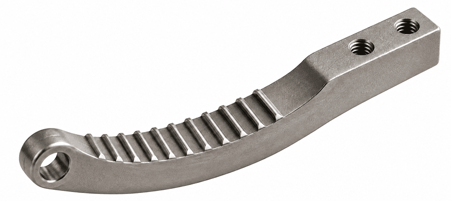
CAM simulation ran clean; simulated minimum clearance spindle-head to fixture riser: 18.4 mm. During the first machine dry run at 10% rapid override in single-block mode, the real machine rotated C-axis in the opposite shortest-path direction during a B-axis reorientation. The operator pressed feed hold when measured clearance dropped below the 25 mm verification limit. No damage. One validation blank scrapped, one 6 mm ball end mill replaced. Downtime: 3.5 hours. Direct cost: USD 786.
Root cause: post rev 4.1 had been copied from an earlier DMU configuration with the opposite C-axis positive-direction mapping. The NX machine model used the correct current kinematics but the post was not linked to that revision. TCP/TRAORI stayed enabled through the failure and was not the source. The CAM simulation ran against the correct machine model; the G-code the post wrote did not.
Fix: locked out rev 4.1; corrected the C-axis sign and shortest-path logic; released rev 4.2; synchronized the NX machine kit to kinematic file DMU50-BC-2026.03; added a mandatory post checksum to release records. Corrected-run minimum clearance measured 17.9 mm. The replacement part passed first article inspection with profile-of-surface tolerance 0.10 mm and measured maximum deviation 0.061 mm.
6.3 Post version, machine kinematics, and controller options
A post is a compiled artifact with a version number. That number must be tied to the exact machine kinematic file and the exact controller option list it was tested against. Shops running multiple 5-axis machines with the same nominal model number often maintain separate posts per serial number because commissioning parameters differ between individual machines. Production programs run through our precision CNC machining carry the post revision, kinematic file version, and controller option list in the setup packet, whether the batch is a prototype or a low-volume production run.
7. Program Verification: What Simulation Proves and What It Does Not
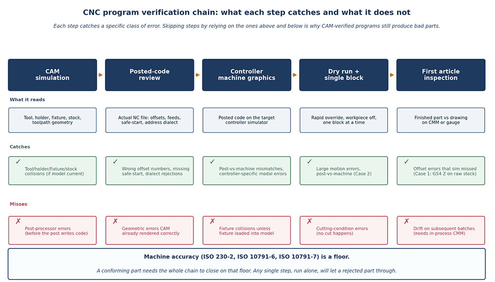
Each verification step catches a specific class of error. Skipping steps by relying on the ones above and below is why CAM-verified programs still produce bad parts.
7.1 CAM simulation, posted-code review, controller graphics
CAM simulation runs the toolpath against the CAM system’s model of machine, fixture, stock, and tool. It catches collisions when the model is current. It cannot catch a post-processor error, because it runs before the post writes the code. Case 2 showed that failure mode.
Posted-code review reads the actual NC file and catches wrong offset numbers, missing safe-start blocks, feeds outside the intended range, and address dialects the target controller will reject. Controller machine graphics replay the posted code on the target controller’s own simulator, catching syntax the controller will not execute and post-vs-machine mismatches CAM simulation cannot see.
7.2 Dry run, single block, feed override, first article
CNC dry run executes the program at rapid override with the workpiece removed. It catches large motion errors and post-vs-machine mismatches like Case 2 but not cutting-condition errors. CNC single block mode executes one line at a time under operator control. Feed override held low through the first pass gives the same margin during a real cut. Neither replaces first article inspection.
First article inspection measures the finished part against the drawing on a CMM or gauge. It catches offset errors that produce a part inside the CAM sim envelope but outside the drawing. Case 1 failed at this step, not at any earlier one. The 6061-T6 thin-wall cavity case held 0.04 mm flatness across six faces because the measurement loop closed at the finished feature, not at the machine.
7.3 What ISO 230-2 and ISO 10791 tests certify
ISO 230-2:2014 measures positioning accuracy and repeatability of NC axes: bidirectional repeatability R, systematic deviation E, reversal value B. A pass says the axes hit commanded positions within specified limits. It says nothing about whether a part is inside its drawing tolerance.
ISO 10791-6:2014 tests speeds and interpolations on machining centers: K1/K2 for spindle and feed, K3/K4 for circular and diagonal interpolation, and AK/BK/CK for rotary interpolation on 5-axis machines. A pass proves the machine can execute geometry the controller commands. It does not prove the program commands the right geometry.
ISO 10791-7:2020 defines a machined test piece with features M1-M5 and required tolerances. A pass demonstrates one specific artifact meets its tolerances. That is the closest of the three standards to production conformance, and it still does not prove any specific customer part conforms. Machine accuracy is a floor; a conforming part needs the chain from CAM through inspection to close on it.
8. What Buyers and Engineers Should Audit Before Releasing an NC Program
The layers above (offsets, tool compensation, controller dialect, post version, verification chain) live inside the supplier’s shop. Buyers see the finished part, the CMM report, and the price. The question is what a purchasing engineer can ask for before the first PO that separates a supplier who runs the chain from a supplier who hopes the chain runs itself.
8.1 Program revision control your supplier should be able to show
A supplier who cannot produce a one-to-one link between drawing revision, CAM revision, post revision, and NC file cannot reproduce a passing batch. That failure surfaces on the second batch, when a program has been edited at the control, an offset re-touched, or a post rebuilt without the CAM re-released.
Core artifacts a supplier should hand you on request: CAM project file and revision history; released NC file with approval record; post name, revision, and file checksum; machine and controller ID; setup sheet; G54-G59 values and tool/wear-offset log as run; first article CMM report; in-process inspection plan; and backup and access-control procedure for the NC master.
8.2 First article inspection and the CMM feedback loop
A good FAI report identifies part, drawing revision, NC file, setup sheet, operator, and inspection date, and reports measured values against every controlled dimension. Pass/fail-only reports give no information about how much margin is left before the next batch drifts out. A first article at the middle of tolerance says the setup is centered; one at the edge on multiple features says the setup is close to a limit the next batch may cross. Reading the CMM report as trend data separates a supplier’s quality function from its inspection function.
8.3 A real supplier audit and the checklist that came out of it
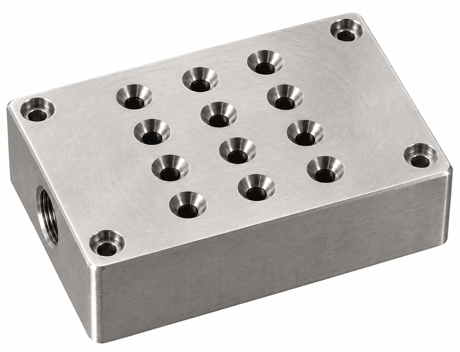
Case 3 (EPOC CRAFTER shop-floor data). New supplier qualification before the first PO on a recurring precision machining program. Part audited: 5-axis machined 316L stainless-steel fluid-control manifold, 118 × 74 × 32 mm, planned lots of 200. The evaluation asked for CAM revision history, NC approval record, post name/revision with checksum, machine and controller ID, setup sheet, G54-G59 and tool/wear-offset records, FAI CMM report, in-process inspection plan, and backup procedure.
Supplier provided: current CAM project, setup sheet, tool list, complete FAI CMM report. NC files stored by job number with manually overwritten filenames. No controlled post-version log, no NC checksum, no approval signature, no retained wear-offset history.
Gap: no traceable one-to-one link among drawing revision D, CAM revision 06, the released NC files, and the post. Operators could edit programs at the control. Wear-offset changes were not attributable to part, shift, or operator. A passing batch could not be reproduced after a program or offset change.
Requirements before PO release: controlled NC naming with read-only master storage; CAM-to-NC release record; post revision and SHA-256 checksum; two-person approval for edited NC files; daily backup; serialized setup sheet; G54-G59 and tool/wear-offset log; FAI plus in-process CMM plan for sealing bores. The supplier issued procedure CNC-PGM-04 rev B, created a read-only release folder, restricted machine-side editing, added CAM revision, post revision, checksum, and approver fields to the setup sheet, exported offset tables at setup approval and end of shift, and trained eight programmers and technicians.
Verification: a witnessed repeat build generated the same NC checksum from CAM revision 06 and post SP-5X-316L rev 2.3. Records for parts 001, 020, 040, and 060 linked serial, machine, operator, G54 value, and wear changes. CMM recheck confirmed all 12 sealing-bore characteristics within tolerance. Outcome: conditional PO for 60 parts, increased receiving inspection for lot 1, follow-up audit passed after lot 2, status upgraded to approved.
| 1 | Drawing revision control | Drawing revision the NC was released against | Revision matches the current released drawing |
| 2 | CAM-to-NC release record | Signed release linking CAM revision to NC file | Signature, date, matching revisions |
| 3 | Post-processor version log | Post name, revision, and SHA-256 checksum | Checksum on setup sheet matches file |
| 4 | NC file storage | Master file location and edit permissions | Read-only master, controlled write access |
| 5 | Machine and controller ID | Machine serial and controller software version | Recorded on setup sheet |
| 6 | Work offset log | G54-G59 values as set and as run | Log entry per lot, tied to first article |
| 7 | Tool and wear offset log | H and D values as set, wear changes as run | Log tied to part serial or shift |
| 8 | First article CMM report | Measured values against every controlled dimension | Values reported, not just pass/fail |
| 9 | In-process inspection plan | Sample size and frequency for controlled features | Documented, tied to sampling standard |
| 10 | Backup and disaster recovery | Backup frequency and restore test date | Daily backup, restore verified in last 12 months |
For the qualification steps before this audit, how purchasing engineers evaluate a CNC supplier covers the shortlist and site-visit stages. The CNC machining quote checklist for China suppliers covers the RFQ package that produces an accurate quote in the first place.
An NC program is not the risk. The governance around it is. A shop that can produce every item above on request is running a program-control system. A shop that cannot is running programs on trust, and the audit makes that visible before the first PO, not after the second batch drifts.
Ready to Quote Your CNC Prototype?
Upload your STEP file and get a DFM review + quote within 12 hours.
No tooling cost. Minimum 1 part.
