

Dewey Wu General Manager & senior mechanical engineer at EPOC CRAFTER, 15 years in design engineering, quality, and metallurgy. Hands-on across CNC machining, metalwork, sheet metal, and prototyping (subtractive + 3D printing).
1. Welding, Explained in One Paragraph
Welding is a fabrication process that joins two or more parts by fusing the base materials at the joint, using heat, pressure, or both, so the finished joint behaves as one continuous piece of metal. That single trait separates welding from brazing, soldering, adhesive bonding, and mechanical fastening, none of which melt the parent metal. What you specify on a drawing depends on the process family among the main types of welding, the joint geometry, the acceptance standard (ISO 5817:2023 for steel, nickel, titanium arc welds; ISO 10042:2018 for aluminum arc welds; ISO 13919-1:2019 for laser and electron beam welds), and the inspection method that signs it off. This guide walks those decisions in the order a welded part moves through a shop, and closes with the post-weld CNC finish machining step most welding overviews skip.
2. How Welding Works: The Physics of a Sound Joint
2.1 Weld Pool, Shielding, and the Fusion Boundary
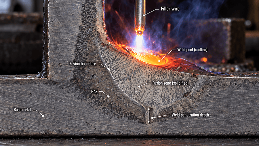
Fusion welding melts the base metal on both sides so the parts share one weld pool; on solidification, atoms from both sides lock into a single crystal structure and the joint becomes the same material as the parent metal. Filler is often added, but the defining move is that the parent metal itself fuses. Solid-state welding takes the opposite route: friction or ultrasonic energy forces clean surfaces into atomic contact without melting, which is why solid-state processes handle dissimilar metals and thin foils fusion would burn through.
Molten steel and molten aluminum react aggressively with oxygen and nitrogen, producing porosity and oxide inclusions that weaken the joint from the inside. Every fusion process protects the pool while it is liquid: shielding gas processes use argon (TIG on aluminum and stainless steel), argon-CO2 (MIG on carbon steel), or helium blends (copper); flux processes generate their own shield from a burning coating or core, as in stick welding (ISO 4063:2023 number 111) and flux-cored arc welding (136 gas-shielded, 138 self-shielded). Flux tolerates outdoor conditions and mill scale; gas needs a clean joint but leaves less slag.
2.2 The Heat-Affected Zone and Why Cooling Rate Decides Strength
The base metal around the weld pool never melts but goes through a full thermal cycle from ambient to close to melting and back. That region is the heat-affected zone (HAZ), and its metallurgical state decides whether a joint that looks fine holds under load. Fast cooling drives steel HAZ into hard, brittle martensite prone to cold cracking; slow cooling softens the zone and cuts fatigue life. Three material behaviors show up repeatedly: austenitic stainless carrying 0.08% carbon can sensitize in the HAZ, which is why 316L drops carbon to prevent sensitization at the HAZ and stays weldable in thicker sections; precipitation-hardened 6061-T6 over-ages in the HAZ, laid out in post-weld temper recovery on 6061 T6 and T651; and 7000-series aluminum has a wide HAZ softening range, which is why 7075 is machined but not welded structurally. The control levers are heat input (amperage × voltage ÷ travel speed), preheat, interpass temperature limits, and post-weld heat treatment when the load justifies it.

3. Welding Process Families by ISO 4063:2023
ISO 4063:2023 assigns every process a numerical code a drawing can reference without ambiguity. The four main groups are 1 (arc welding), 2 (resistance welding), 4 (pressure welding, covering solid-state), and 5 (beam welding).
[Image] file name: iso-4063-welding-process-families.svg | alt text: ISO 4063:2023 process-number tree showing arc, resistance, beam, and solid-state welding groups with sub-process numbers
3.1 Arc Welding (Group 1: 111, 131, 135, 136, 141)
- 111 SMAW (stick welding). Flux-coated consumable electrode. Handles thick sections, rusty stock, and outdoor work.
- 131 MIG, 135 MAG (GMAW). Solid wire fed continuously, shielded by argon (131) or argon-CO2 (135). Fast, automatable; dominant in high-volume steel and aluminum. Aluminum needs a push-pull feeder. The MIG vs TIG welding trade-off is covered separately.
- 136 FCAW. Tubular wire with flux inside plus external gas. Higher deposition than solid-wire MIG at the same amperage; used on heavy plate.
- 141 TIG (GTAW). Non-consumable tungsten electrode with filler fed separately. Slowest and most controllable. Default for welding stainless steel piping, welding aluminum thin sheet on AC, titanium welding under argon, and cosmetic welds.
For sheet metal assemblies combining laser-cut blanks with brackets or enclosures, in-house TIG and MIG welding on the sheet metal line keeps the fabrication chain under one roof.
3.2 Resistance Welding (Group 2: 211, 212)
Current through clamped workpieces; interface resistance generates the heat while pressure forges the joint. 211 spot welding fuses a nugget between two copper electrodes (tens of thousands of amps for tens to hundreds of milliseconds); automotive body-in-white runs on it. 212 seam welding uses rotating wheels for leak-tight joints on fuel tanks and radiators. Both need conductive base metal and access from both sides.
3.3 Beam and Solid-State (Groups 5 and 4)
Beam welding delivers energy through a focused photon or electron beam, producing narrow deep welds with a small HAZ. Laser welding (521, 522, 523) runs deep keyhole welds at travel speeds arc processes cannot match, but tolerates only about 10% of material thickness in joint gap. Electron beam welding delivers deeper welds in a vacuum chamber for aerospace and titanium airframe parts. Beam welding is where ISO 5817:2023 stops applying; quality levels come from ISO 13919-1:2019. Solid-state processes (group 4) join without melting: friction stir welding is standard for 5000 and 6000-series aluminum aerospace panels, and ultrasonic welding handles battery tabs and copper-to-aluminum current collectors where fusion would form brittle intermetallics.
3.4 Choosing a Family: Material, Thickness, Position, Loading Case
- Material. Carbon steel, low-alloy steel, and 300-series stainless run on arc processes. Aluminum divides sharply by series, a boundary in 5052 versus 6061 aluminum and their weldability. Titanium needs argon on both top and back.
- Thickness. Below 1 mm: TIG (141) or laser (521). 1 to 6 mm: MIG (131, 135) and TIG. Above 6 mm: SMAW (111), FCAW (136), submerged arc.
- Position. TIG and stick run in every position. MIG runs best flat or horizontal. Laser and EBW run wherever the fixture goes.
- Loading and acceptance standard. Static structural: ISO 5817:2023 level C. Fatigue-critical: level B. Beam welding on aerospace or medical: ISO 13919-1:2019 level B.
4. Weld Joint Configurations and Penetration
The process family answers “what tool”; the joint configuration answers “what shape”. Six standard configurations cover almost every welded assembly.
| Butt | 135° to 180° | End-to-end plates or pipes, load-bearing seams |
| T | Above 5° up to 90° | Stiffener or rib against a flat plate |
| Corner | Above 30°, less than 135° | Two plates at an outside corner, box enclosures |
| Edge | 0° to 30° | Thin sheet stacked edge-on without full penetration |
| Cruciform | Two plates welded to a third at right angles | Structural nodes and moment connections |
| Lap | 0° to 5° (overlapping) | Overlapping sheets, automotive spot welds |
Angles follow ISO 15607 and ISO 9692-1 and match AWS A3.0M/A3.0. Two DFM points matter: joint access decides the process (a T joint in a deep pocket forces the fabricator off MIG onto TIG, which costs more per inch), and fit-up decides quality (a butt joint at 0 mm root gap cut by shear instead of laser shows a 0.5 to 1.0 mm gap after fit-up, pushing the weld into lack-of-fusion territory). Fit-up tolerance is a drawing responsibility; the clearance rules in hole-to-edge distances that keep a weld torch reachable prevent access problems at the drawing stage.

Weld penetration is how deep the fused metal reaches. Full penetration (CJP in AWS D1.1) fuses through the full thickness; standard for pressure vessels and safety-critical connections. Partial penetration (PJP) leaves an unfused root, correct when the joint carries shear load instead of tensile load through the throat. Effective throat, not the visible weld leg, decides load capacity.
5. Welding Imperfections vs Defects (ISO 6520-1:2007)
ISO 6520-1:2007 treats “imperfection” and “defect” as different concepts. An imperfection is any deviation from the ideal weld. A defect is an imperfection whose size, quantity, or location exceeds the specified quality level. A weld can contain visible porosity or minor undercut and still pass. A drawing that says “no defects” without naming a quality level is unenforceable.
- Group 100, cracks. Longitudinal (101), transverse (102), crater (104). ISO 5817:2023 levels B, C, and D all set the crack acceptance limit at zero for load-bearing joints.
- Group 200, cavities. Distributed porosity (2011), cluster porosity (2013), elongated cavities (2015). Welding porosity comes from shielding gas loss, moisture, or filler contamination. Aluminum tolerates higher porosity than steel under ISO 10042:2018 because aluminum pools trap hydrogen more easily.
- Group 300, solid inclusions. Slag (301), tungsten (3041), copper (3042). Detected by radiography.
- Group 400, lack of fusion and penetration. Lack of fusion (401), incomplete penetration (402), spiking (403). Show up when heat input is too low or the joint is too tight for the torch.
- Group 500, imperfect shape and dimensions. Weld undercut (5011, 5012), excess weld metal (502), overlap (506), linear misalignment (507). ISO 5817:2023 caps undercut depth at 0.5 mm and 5% of plate thickness for level B; 1 mm and 10% for C; 1.5 mm and 10% for D.
- Group 600, miscellaneous. Stray arc strikes (601), spatter (602), grinding marks (603). Affect cosmetic acceptance.
Welding distortion is imperfection 520 in group 500, and is the reason §9 exists.
6. Weld Quality Levels: How to Specify a Weld That Actually Passes
Three ISO standards cover weld quality levels, and the boundary between them is decided by process and material. A drawing that calls out the wrong one is unenforceable. Each standard defines three levels: B (stringent), C (intermediate, and the default when the drawing says nothing), D (moderate). Over-specifying B on a non-critical bracket adds cost without adding fitness for purpose.
6.1 ISO 5817:2023 (Steel, Nickel, Titanium Arc Welds)
Fusion-welded joints (except beam welding) at 0.5 mm and above. Aluminum and beam welding are explicitly excluded. Level B fits fatigue-critical joints, pressure vessels, and aerospace primary structure; C covers most industrial welding and structural steelwork; D fits static loads with generous safety factor.
6.2 ISO 10042:2018 (Aluminum Arc Welds)
Covers aluminum MIG (131), TIG (141), and plasma arc welding. Surface porosity limits are aluminum-specific: 0.5% at level B, 1% at level C, 2% at level D, far more permissive than steel because aluminum pools trap hydrogen and produce fine porosity that is metallurgically unavoidable at low levels. Temper selection determines whether a level B aluminum joint is producible: 6061 grades and how they arc-weld covers this.
6.3 ISO 13919-1:2019 (Laser and Electron Beam Welds)
Beam-welded steel, nickel, and titanium joints. Laser and EB welds have narrower geometries than arc welds, needing their own standard instead of borrowing from ISO 5817:2023. Aluminum laser welding has no current ISO acceptance standard; drawings reference internal quality plans or ASTM standards.
6.4 Standard Matrix
| Arc (111, 131, 135, 136, 141) | ISO 5817:2023 B / C / D | ISO 10042:2018 B / C / D |
| Laser (521, 522, 523) | ISO 13919-1:2019 B / C / D | No current ISO standard; customer spec or ASTM |
| Electron beam | ISO 13919-1:2019 B / C / D | No current ISO standard; customer spec or ASTM |
| Resistance spot / seam (211, 212) | ISO 15614-12 procedure qualification; acceptance per customer spec | Same |
The rule: match the standard to the intersection of process family and material, and name the level (B, C, or D) on the drawing.

7. Weld Inspection: Getting from Standard to Acceptance
Specifying a quality level is only half the acceptance chain. The other half is the inspection method that verifies it, its sampling rate, and its acceptance level.
7.1 ISO 17635:2025 NDT Method Selection
ISO 17635:2025 sets which NDT welding methods suit which material, thickness, and imperfection type, pointing to the method-specific standards (RT to ISO 17636, UT to ISO 17640, penetrant to ISO 3452, magnetic particle to ISO 17638, visual to ISO 17637:2016). No single method finds everything: radiography sees porosity and slag but struggles with tight cracks; ultrasound finds cracks and lack of fusion but needs trained operators; penetrant catches surface flaws on any material; magnetic particle catches surface flaws on ferromagnetic materials. A drawing that specifies ISO 5817:2023 level B without naming an NDT method leaves half the acceptance chain undefined. ISO 17635:2025 also distinguishes quality level (the weld itself) from acceptance level (how the NDT method reports what it found).
7.2 ISO 17637:2016 Visual Testing (350–500 lx, 600 mm, 30°)
Visual testing (VT) is the first inspection on every welded assembly. ISO 17637:2016 sets the parameters that make VT repeatable instead of subjective:
- Illuminance at the surface: minimum 350 lx, recommended 500 lx.
- Eye-to-surface distance: no more than 600 mm.
- Viewing angle: at least 30° from the weld surface (looking straight down the axis hides toe undercut on the far side).
- Access: direct VT preferred; indirect VT (mirrors, borescopes) only where geometry blocks direct access.
A VT report that does not record these four parameters is not compliant with ISO 17637:2016.
8. Dimensional Tolerances of Welded Structures (ISO 13920:2023)
ISO 5817:2023 controls what happens inside the weld; ISO 13920:2023 controls the overall shape of the weldment. A welded assembly can pass every ISO 5817:2023 check and still fail dimensionally because the finished part shifted during welding. ISO 13920:2023 uses letter classes instead of numbers so they cannot be confused with B/C/D quality levels.
Linear and angular, classes A to D. A tightest, D loosest, B the default. On 3,000 mm nominal length: A permits ±3 mm, B ±6 mm, C ±10 mm, D ±16 mm. A 90° angle over 100 mm carries about ±30′ at A and ±90′ at D. A welded frame drawn at 3,000 mm nominal with no tolerance callout is by default acceptable at ±6 mm, far looser than most downstream interfaces expect.
Straightness, flatness, parallelism, classes E to H. E tightest, H loosest. F is the default for general fabrication. Cover twist, panel flatness, and parallelism of mating surfaces on features the drawing did not tolerance individually.
Any dimension that will be a machining datum, an assembly interface, or a mating face must carry its own explicit tolerance tighter than class B / class F defaults, or be finish-machined after welding. GD&T interaction is covered in tolerance callouts on a drawing that includes a welded assembly.
9. Post-Weld CNC Finish Machining: The Sequence That Makes the Weldment Fit
The gap between ISO 13920:2023 class B (±6 mm on 3,000 mm) and a machined bore held at ±0.05 mm is two orders of magnitude. Weldments with precision interfaces almost never ship at final dimensions from the welder.
9.1 Why Weldments Never Ship at Final Dimensions
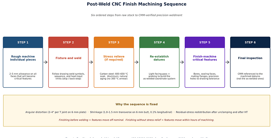
Three physical effects push a welded assembly out of tolerance. Angular distortion rotates plates as the pool solidifies asymmetrically; a T joint on 6 mm plate pulls the flange 2° to 4° off nominal after a single-side fillet. Shrinkage contracts the joint on cooling; butt welds on 6 mm carbon steel shrink about 1.0 to 1.5 mm transversely and 0.1% longitudinally. Residual stress redistribution shows up after unclamping and again after heat treatment. Fixtures and sequence reduce these but do not eliminate them.
9.2 Which Features Must Not Be Finished Before Welding
Any feature with a tolerance tighter than the ISO 13920:2023 class that applies must not be finish-machined before welding: bearing bores, sealing faces, precision mounting holes, datum surfaces, mating flanges, and any Ra callout below 3.2 μm. Features safe to finish before welding are the ones the weld does not disturb (through-holes at least three to four material thicknesses from any weld toe). The Six-Gate DFM rules that reduce distortion before welding include the pre-weld feature audit.
9.3 The Sequence: Allowance, Datum, Stress Relief, Finish
- Rough machine individual pieces with 2 to 5 mm of allowance on faces that will become critical features after welding.
- Fixture and weld to the drawing’s weld symbols and heat input limits. Skip-welding, back-step technique, and balanced heat input reduce distortion at the source.
- Stress-relieve if required. Carbon steel weldments destined for machined features usually get thermal stress relief (soak at 600 to 650 °C) before machining. Aluminum weldments are usually not thermally relieved because 300 °C anneals the T6 HAZ; natural aging or partial re-solution treatment is used instead, following 6061 T6 versus T651 temper selection.
- Re-establish datums. The first CNC operation on a welded assembly is a light facing pass on the primary datum, then probing to build a coordinate system tied to the actual as-welded geometry.
- Finish-machine critical features from the re-established datums, then final inspection on a CMM referenced to the machined datums.
Running finish machining on the same shop floor as welding cuts setup errors from re-fixturing at a different supplier. The end-to-end workflow where welding and CNC finish machining stay under one roof makes this practical, backed by CNC machining capability for post-weld finish operations. The logic mirrors the machining allowance approach used on cast blanks.
10. Welding Safety Basics
- Arc flash and radiation. UV and IR burn skin and cornea within seconds. Auto-darkening helmets to EN 379 or ANSI Z87.1, long sleeves, dark leather gloves; screens for nearby workers.
- Fumes and gases. Galvanized steel releases zinc oxide (metal-fume fever); stainless releases hexavalent chromium under OSHA action limits; aluminum releases ozone. Local exhaust at the arc, fresh-air respirator for enclosed or long-duration work.
- Fire and hot metal. Sparks travel several meters and stay hot enough to ignite combustibles for 30 minutes after the arc stops. Hot-work permits, clear zones, fire watch, Class ABC extinguisher.
- Electrical shock. Keep gloves dry, insulate the body from the workpiece, check the ground clamp before every start.
11. Pre-RFQ Checklist for Welded Parts
What a fabricator needs on a drawing before quoting a welded assembly.
- Material and temper by full designation (S355J2+N, 304L, 6061-T6, Ti Grade 5).
- Joint configuration and weld symbols per ISO 2553 or AWS A2.4, with throat size or leg length for fillet welds and penetration depth for partial penetration groove welds.
- Process family if the part requires a specific one (TIG for cosmetic stainless, spot welding for automotive sheet, laser for hermetic seals).
- Quality level and standard: ISO 5817:2023 B/C/D for steel/nickel/titanium arc; ISO 10042:2018 for aluminum arc; ISO 13919-1:2019 for laser and electron beam.
- Inspection method per ISO 17635:2025, ISO 17637:2016 when VT is the sole method, sampling rate stated (100% VT + 10% RT, for example).
- Post-weld operations: stress relief, machining allowance, and post-weld tolerance class per ISO 13920:2023.
Send the file for rapid prototyping with welded brackets and enclosures with these covered and DFM feedback comes back in hours.
12.Common Engineering and Procurement Questions
What is the practical difference between welding, brazing, and soldering?
Welding fuses the base metals above their melting points; the joint is the same material as the parent metal. Brazing joins parts with filler that melts above 450 °C while the base metals stay solid. Soldering uses filler below 450 °C. Specify welding when the joint carries structural load or must match parent-metal fatigue life.
Which welding quality level (B, C, or D) should I put on a drawing?
Match to the loading case. B fits fatigue-critical, pressure-containing, or safety-critical joints. C fits general industrial machinery and is the default when nothing is specified. D fits static-load parts with generous safety factor.
How much machining allowance for post-weld CNC finishing?
Two to five millimeters on faces that will become critical features after welding. Long butt seams on carbon steel and heavy T joints on thick plate live at the upper end.
If a weld passes visual but I need proof of internal soundness, what inspection do I ask for?
Radiographic testing (RT) for porosity, slag inclusions, and lack of penetration on joints with beam access. Ultrasonic testing (UT), including phased-array UT, for cracks and lack of fusion in thicker sections. Name both the acceptance standard (ISO 5817:2023 level B) and the NDT method (RT to ISO 17636-1 level B) on the drawing.
Related Resources
- Related Capability: sheet metal fabrication with TIG and MIG welding. Welded brackets and enclosures cut, formed, welded, and inspected in-house.
- Related Article: sheet metal design guidelines and Six-Gate DFM check. DFM rules that reduce distortion before the first arc strike.
- Related Standards Reference: how to tolerance a CNC drawing that includes a welded assembly. GD&T callouts for weldments.
- Related Material Guide: sheet metal materials guide covering weldability of 5052, 6061, 304, and 1018. Grade-level weldability for the four most common sheet metal materials.
- Related Article: 316 vs 316L stainless steel and the HAZ argument. Why 316L is the welder’s grade.
Ready to Quote Your CNC Prototype?
Upload your STEP file and get a DFM review + quote within 12 hours.
No tooling cost. Minimum 1 part.
