

Dewey Wu General Manager & senior mechanical engineer at EPOC CRAFTER, 15 years in design engineering, quality, and metallurgy. Hands-on across CNC machining, metalwork, sheet metal, and prototyping (subtractive + 3D printing).
W-Ni-Fe tungsten heavy alloy can be CNC machined with carbide tools, but the material callout must come before the cutting data. ASTM B777-15(2026) defines four classes of machinable high-density tungsten-base metal from 90 to 97 wt% W. It does not prescribe feeds, speeds, coolant, tool life, or finished-part tolerances. This guide focuses on W-Ni-Fe heavy alloy for precision tungsten machining within the broader family of refractory metals. Pure tungsten, W-Ni-Cu heavy alloy, and WC-Co tungsten carbide appear only where the distinction changes sourcing, machining, or inspection. The main risks are tool wear, cutting heat, unsupported edges, interrupted cuts, and poorly defined acceptance requirements.
1. What Is Tungsten Metal in a Machining RFQ?
Tungsten is a refractory metal element, also called wolfram. In a machining RFQ, “tungsten metal” is still too broad. Pure tungsten, tungsten heavy alloy, W-Ni-Cu alloy, and tungsten carbide can all appear in search results for machining tungsten, yet they are different workpiece systems.
For machining, broad tungsten properties such as tungsten density, tungsten strength, tungsten hardness, and tungsten melting point do not identify the grade. The drawing needs the material system and, for heavy alloy, the applicable ASTM B777 class before the shop selects cutting data.
1.1 W-Ni-Fe Heavy Alloy vs Pure Tungsten
Pure tungsten and W-Ni-Fe heavy alloy should not share one machining data set. ASTM B760-07(2023) covers wrought unalloyed tungsten plate, tungsten sheet, and tungsten foil. ASTM B777 covers sintered high-density tungsten alloy with a binder matrix. B760 does not cover tungsten rod, tungsten bar, powder, or B777 heavy alloy.
For a CNC-machined heavy tungsten alloy part, a callout such as “ASTM B777 Class 3, W-Ni-Fe tungsten heavy alloy” is stronger than “tungsten” or “95% tungsten.” It establishes the material class and acceptance framework. The case later in this article uses a nominal 95W-3.5Ni-1.5Fe supplier grade with an MTR/CoC tied to a defined lot.
For adjacent material choices, the CNC machining material selection guide compares material choice against cycle time, tool life, setup count, inspection, and finished-part cost.

1.2 W-Ni-Cu and Nonmagnetic Requirements
W-Ni-Fe is not the only tungsten nickel alloy route. ASTM B777 distinguishes standard and nonmagnetic alloys. Where magnetic response affects the assembly, the purchase order must state the requirement. The 2026 standard defines nonmagnetic material as maximum magnetic permeability 1.05, and Class 4 is not available as a nonmagnetic grade.
A compact tungsten counterweight may accept a standard W-Ni-Fe grade. A component near magnetic sensing or electron-optical hardware may require a nonmagnetic route such as a tungsten nickel copper system or another qualified B777 composition. Material selection should follow density, ductility, magnetic response, geometry, and inspection needs.
2. What ASTM B777 Defines for Tungsten Heavy Alloy
ASTM B777-15(2026) defines the material lot, class, density, maximum Rockwell C hardness, minimum tensile properties, microstructure, testing, marking, and purchase-order requirements. It applies to machinable tungsten-base high-density metal produced by tungsten powder metallurgy and sintering. It does not define a CNC process window.
2.1 Class 1 to Class 4
Class selection changes density, hardness limits, and ductility. Use the class that matches the part function, then validate machining on the actual material lot.
| Class | Nominal W | Density, g/cm³ | Max HRC | Decision meaning |
| 1 | 90 wt% | 16.85 to 17.30 | 32 | Lowest density in B777; 5% minimum elongation for standard alloy. |
| 2 | 92.5 wt% | 17.15 to 17.85 | 33 | Higher density; same 5% minimum standard-alloy elongation as Class 1. |
| 3 | 95 wt% | 17.75 to 18.35 | 34 | Case material in this article; 3% minimum standard-alloy elongation. |
| 4 | 97 wt% | 18.25 to 18.85 | 35 | Highest density; 2% minimum standard-alloy elongation; no nonmagnetic grade. |

2.2 Coupon Data, Microstructure, and Traceability
ASTM B777 requires tungsten particles to be uniformly distributed in the binder-metal matrix and examines microstructure at 200×. One powder inspection lot is based on a uniform powder blend. At least two sintered test bars are produced for each powder inspection lot, with hardness, density, tensile, tungsten-content, and microstructure checks assigned by the standard.
Coupon results are not proof that every location in a large finished part has identical properties. B777 states that sintered properties can vary with part size and sampling location. A purchase order that needs local part-property evidence must define an additional part-specific test program. For routine tungsten machined parts, lot-level certification may be enough. Critical large sections may need a tighter acceptance plan.
3. Properties That Change W-Ni-Fe Machining
Bulk hardness alone does not explain tungsten machinability. Tungsten metal properties should not be transferred from a pure tungsten datasheet to W-Ni-Fe heavy alloy. W-Ni-Fe is a multiphase material, so the cutting edge repeatedly crosses tungsten-rich particles and the more ductile Ni-Fe binder. Tungsten content, binder fraction, blank condition, tool geometry, local support, and cutting engagement all change the result.
3.1 Tungsten Content, Density, Strength, and Ductility
ASTM B777 shows a clear class trend: nominal tungsten content and tungsten alloy density rise from Class 1 to Class 4, while attainable ductility falls. Standard-alloy minimum elongation drops from 5% in Classes 1 and 2 to 3% in Class 3 and 2% in Class 4. The standard also defines class-specific tungsten tensile strength and tungsten yield strength requirements.
Those acceptance values should not be converted into feeds and speeds. A 2021 machining study on 90%, 95%, and 97% tungsten heavy alloys found that higher tungsten content increased cutting force under the tested conditions, while surface roughness decreased. Feed rate had a strong effect. One property cannot predict the complete cut.
3.2 Melting Point, Thermal Properties, and Cutting Heat
Tungsten melting point and tungsten heat resistance are useful material topics, but they do not explain conventional tungsten machining by themselves. The workpiece is not cut near the melting point of elemental tungsten. At the tool edge, cutting force, friction, local temperature, heat flow, tool geometry, and wear control the process. The broader relationship between material properties, tool life, cycle time, and cost is covered in our CNC machining materials and machinability guide.
Tungsten thermal conductivity and tungsten thermal expansion affect heat flow and dimensional stability, but ASTM B777 does not assign one universal value to every heavy alloy. The same limit applies to tungsten elastic modulus. Use supplier data or a qualified material data sheet when those properties affect the design.
4. Tool Wear, Cutting Heat, and Parameter Limits
W-Ni-Fe machining becomes unstable when tool wear changes the edge geometry faster than the process can tolerate. A 2026 Tribology International study linked progressive tool wear in tungsten alloy cutting with edge-radius growth, stronger ploughing, higher cutting temperature at increased cutting speed, and changes in machined surface topography.
4.1 Tool Wear Before Tool Breakage
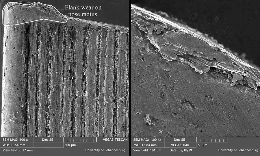
The EPOC case used flank wear and finish loss as the primary tool-life criteria. The roughing edge was changed at about VB 0.20 mm or earlier when surface-finish or dimensional trends approached the drawing limit. Recorded roughing tool life was 38 minutes of cutting time, equal to 12 parts per edge. The observed pattern was progressive abrasion with minor edge chipping at the depth-of-cut line. No catastrophic fracture occurred in the accepted process.
These values belong to one Class 3 job. They are not universal tungsten machining parameters. The useful control method is to watch wear, surface finish, and dimensional drift together.
4.2 Coolant and Cutting Data Need Full Context
The case used 8% measured water-soluble coolant for milling and through-tool coolant for drilling and reaming. The number is not a default coolant concentration for tungsten alloy machining. Coolant chemistry, concentration, pressure, filtration, hole depth, tool design, and chip evacuation can change the result.
A feed or cutting speed has the same limitation. The parameter must stay attached to the material class, tool, diameter, flute count, engagement, coolant, setup, and feature. ASTM B777 does not prescribe tungsten machining feeds and speeds.
5. Turning, Milling, Drilling, Grinding, or EDM?
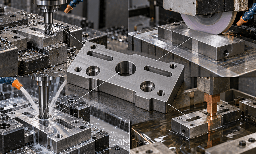
Process selection should follow the feature. Conventional CNC turning and milling suit accessible geometry with good support. Drilling often prepares a hole for a sizing operation. Grinding tungsten is useful for controlled stock removal on flat or finished surfaces. EDM is worth considering when tool access, cutting force, or fragile geometry makes mechanical cutting risky.
5.1 Milling and Turning
Milling tungsten heavy alloy is practical for faces, profiles, pockets, and accessible slots when the setup supports the cut. Tungsten milling risk rises at unsupported exits and interrupted profiles. Turning tungsten follows the same rule: continuous, well-supported geometry is easier to control than thin flanges or interrupted diameters.
The CNC machining services for difficult metal parts page shows the available milling, turning, EDM, and inspection routes used when a drawing needs more than one operation.
For high-value parts, machining tungsten alloy should start with a documented process and move only after wear and surface results are stable. A 2025 Journal of Materials Research and Technology study on 95W-3.5Ni-1.5Fe treated high cutting force, tool wear, and poor surface quality as the main problems in conventional cutting, which is why the authors tested an assisted process.
5.2 Drilling, Reaming, and Threads
The Class 3 case used an Ø11.8 mm through-coolant carbide drill before finishing a Ø12 H7 bore with a carbide reamer. For the dimensional meaning and manufacturing implications of H7, see ISO 286 H7 fits for CNC machined bores. Drilling tungsten created the bulk hole; reaming controlled final size and finish. The finished bore measured 12.009 to 12.015 mm against a 12.000 to 12.018 mm drawing limit, with Ra 0.62 µm against Ra ≤0.8 µm.
Four M6 × 1 threads were produced with a solid-carbide thread mill in three radial passes. Drawing notation, pitch, tolerance class, and thread-depth requirements are covered in the metric thread chart and tapped hole callouts guide. Thread milling reduced the consequence of a broken tap in an expensive dense part. Tapping can still be a valid production route after validation, especially on simple through holes.
5.3 Grinding and EDM
Grinding tungsten can finish a flat datum, a controlled surface, or a small remaining allowance. Compare achievable Ra values across milling, turning, grinding, and EDM in the surface roughness Ra requirements for CNC machining and grinding guide. The case blank arrived with ground reference faces, which improved setup repeatability before milling. Tungsten grinding can also be useful when another milling pass would load a fragile edge.
EDM removes mechanical cutting force from the feature. It can help with narrow internal geometry, limited tool access, thin sections, or profiles that would require excessive tool overhang. EDM brings its own surface-integrity and productivity questions, so it should solve a defined geometry problem instead of replacing every conventional operation.
6. Features That Raise Scrap Risk
Unsupported exits, interrupted cuts, deep holes, thin sections, and combined size-position-finish requirements deserve the most attention during DFM. The Class 3 case showed this directly. Early slot-exit breakout reached 0.18 to 0.25 mm on 5 of 12 trial parts against a functional-edge limit of 0.10 mm. Similar feature-level risks, including unsupported walls, deep pockets, excessive tool reach, and unnecessary tight tolerances, are covered in CNC prototype DFM mistakes that increase machining scrap risk.
Soft-jaw support was moved closer to the slot exit, finishing radial engagement was reduced, and the final contour was split into two light passes. After the change, breakout stayed between 0 and 0.07 mm on all 36 checked parts. The material class did not change. The support and finishing strategy did.
The same feature review belongs in the CNC DFM guidelines for tool access and feature support, where pocket access, hole depth, wall support, and datum choices are checked before release.
6.1 Precision Bores and Datum Strategy
The critical bore carried three requirements: Ø12 H7 size, Ø0.030 mm position to A|B|C, and Ra ≤0.8 µm. Datum A also had 0.025 mm flatness, with 0.030 mm parallelism on the opposite face. The operation sequence established A/B/C before final bore and profile work.
This is where tight tolerance machining should be assigned by feature. A drawing that tightens every dimension adds tool changes, finishing passes, and inspection without improving function. A stable datum system and a clear inspection method are more useful than a blanket “high precision” note.
The tight tolerance machining by feature guide applies the same rule to bores, fits, locating patterns, and mating faces: tighten the features that can fail the assembly, not the whole drawing.
7. Case: ASTM B777 Class 3 W-Ni-Fe Counterweight
The project was a precision counterweight insert for an automated optical positioning assembly. The customer is anonymized. Starting stock was an as-sintered 95 × 55 × 25 mm tungsten block with ground reference faces. Finished size was 82 × 44 × 18 mm. Production covered 6 prototypes, a 48-piece batch, and an annual volume of 600 parts. The workflow from initial process validation into repeatable batch machining follows the same principles described in CNC machining for prototyping and low-volume production.
The part ran on a 3-axis vertical machining center in three setups. Ground parallels and custom aluminum soft jaws provided broad contact, with support close to the cut. Tooling included fine-grain carbide end mills, a carbide drill, a carbide chucking reamer, and a solid-carbide thread mill. The milling tools used positive-rake variable-helix geometry with AlTiN coating.
7.1 Verified Cutting Data
The values below come from case record WHA-CNC-2026-014. They are linked to one Class 3 material lot, tool set, fixture, coolant condition, and geometry.
| Operation | Tool | Vc | Feed | DOC / WOC or stock | Decision meaning |
| Face/profile roughing | Ø10 mm, 4-flute carbide end mill | 45 m/min | 260 mm/min; 0.045 mm/tooth | 0.8 mm / 4.0 mm | Bulk removal with supported engagement. |
| Pocket/slot roughing | Ø8 mm, 4-flute carbide end mill | 40 m/min | 220 mm/min; 0.035 mm/tooth | 0.6 mm / 2.5 mm | Lower engagement for slot and pocket load. |
| Finish contour/faces | Ø6 mm, 4-flute carbide end mill | 55 m/min | 175 mm/min; 0.015 mm/tooth | 0.15 mm / 0.25 mm | Light finishing engagement near edge-sensitive geometry. |
| Pre-drill Ø12 bore | Ø11.8 mm through-coolant carbide drill | 28 m/min | 57 mm/min; 0.075 mm/rev | 18 mm full depth; short peck | Create the bulk hole and preserve stock for sizing. |
| Finish ream Ø12 H7 | Ø12.0 mm carbide reamer | 10 m/min | 32 mm/min; 0.12 mm/rev | 0.20 mm diametral stock | Separate final bore size and finish from drilling. |
| M6 × 1 thread milling | Ø4 mm solid-carbide thread mill | 25 m/min | 120 mm/min | 3 radial passes: 0.15 / 0.10 / 0.05 mm | Progressive thread generation limits the consequence of tool failure. |
Coolant: 8% measured water-soluble flood coolant for milling; through-tool coolant for drilling and reaming. These are measured case values, not default tungsten machining settings.
7.2 Results and Corrective Action
The accepted process held the Ø12 bore at 12.009 to 12.015 mm, maximum position error at 0.021 mm to A|B|C, bore roughness at Ra 0.62 µm, and datum A roughness at Ra 1.18 µm. Cycle time was 24.8 minutes per part, measured across 10 consecutive production parts and including in-process tool-change allowance.
The 48-piece batch recorded 0 scrap and 1 rework. Moving from a validated prototype process to repeated batches also requires stable fixtures, tool-life limits, inspection frequency, and first-article controls, as discussed in low-volume CNC production and process scale-up.The rework came from early slot-exit breakout and was corrected by local blending within the drawing allowance. These figures are measured project data, not a tungsten machining yield claim.
8. What to Put on the Drawing and Purchase Order
A purchase order should identify the ASTM B777 class, alloy or magnetic requirement, drawing revision, critical dimensions, surface finish, edge condition, certificate package, lot traceability, and inspection expectations. “Tungsten alloy” is not enough.
For drawing release, use engineering drawing tolerances for CNC parts to separate default tolerances, fits, GD&T, datum references, and inspection notes.
8.1 Material, Certification, and Part-Specific Testing
For the case part, the material callout was ASTM B777 Class 3 with nominal 95W-3.5Ni-1.5Fe composition. MTR/CoC records were tied to lot WHA-260918-B. The publication record also lists setup photos, a worn-tool microscope image, the CMM report, roughness record, and final dimensional sheet.
For programs that need the same material identity to follow machining, inspection, finishing, and shipment, end-to-end manufacturing with material certificates and inspection records is the relevant capability path.
When local material properties matter on a large or critical section, define the extra test in the purchase order. B777 coupon acceptance does not establish identical properties at every point in a large finished part.
8.2 Tolerances, Surface Finish, and Inspection
Use feature-specific values. The case called for Ra ≤0.8 µm in the precision bore, Ra ≤1.6 µm on datum A and mating faces, and Ra ≤3.2 µm on other machined faces. Functional-edge breakout was limited to 0.10 mm, with a 0.2 to 0.4 mm edge break unless otherwise specified.
Inspection should match the requirement. The case used CMM data for dimensional and positional results, a contact stylus profilometer with 0.8 mm cutoff for roughness, and microscope checks for tool wear. These records make acceptance repeatable for the shop and buyer.
Use the CNC tolerance and GD&T standards resource when the drawing needs a documented tolerance or inspection basis beyond the material specification.
9. Tungsten Uses That Justify Difficult Machining
ASTM B777 lists tungsten applications such as tungsten weights and counterbalances, high-speed rotating inertia members, tungsten radiation shielding, hypervelocity impact, and vibration damping. These uses justify high density where part envelope or attenuation is more important than easy machining.
The case in this article is a tungsten counterweight for an optical positioning assembly. Other tungsten machined parts can include tungsten balance weights, inertia components, and shielding inserts. The density advantage only earns its cost when the system needs it. A lower-density metal is a better procurement choice when mass or attenuation does not drive the design.
10. Questions Engineers Ask Before Quoting Tungsten Machining
10.1 Can tungsten be machined?
Yes. ASTM B777 describes machinable high-density tungsten-base metal, and W-Ni-Fe heavy alloy can be milled, turned, drilled, reamed, thread milled, ground, or EDM machined. Pure tungsten and tungsten carbide need separate process assumptions.
10.2 Is tungsten hard to machine?
W-Ni-Fe heavy alloy is difficult to cut because tool wear, cutting force, local heat, part support, and surface integrity can narrow the stable process window. “Hard to machine” is more useful as a risk flag than as a single machinability rating.
10.3 Is tungsten brittle?
B777 shows lower attainable ductility as tungsten content rises. That does not make every tungsten alloy feature brittle in the same way. Unsupported edges, interrupted cuts, thin sections, and finishing engagement determine whether local breakout becomes a production problem.
10.4 Is tungsten magnetic?
Do not apply one answer to every tungsten alloy. B777 allows alloys that can be weakly ferromagnetic and provides a nonmagnetic grade definition. Class 4 is not available as a nonmagnetic grade. Put the magnetic requirement in the purchase order when the assembly is sensitive to it.
10.5 What is tungsten used for in machined parts?
W-Ni-Fe heavy alloy is used where compact mass, radiation attenuation, inertia, or vibration behavior justifies the material. Common uses of tungsten heavy alloy include counterweights, balance weights, inertia members, and shielding components.
10.6 Tungsten vs tungsten carbide: what changes in machining?
Tungsten metal and WC-Co tungsten carbide are not the same material. W-Ni-Fe heavy alloy is a tungsten-rich metal composite with a metallic binder. Cemented tungsten carbide is a hard carbide material commonly used for cutting tools. A tungsten carbide vs tungsten comparison must keep those material systems separate.
11. Release the RFQ with the Material and Inspection Plan
Send the drawing with the ASTM B777 class, quantity, critical tolerances, surface-finish requirements, magnetic requirement when needed, MTR/CoC expectation, and inspection scope. That gives the supplier enough information to choose a machining route and flag features that need grinding, EDM, special support, or extra inspection.
For W-Ni-Fe tungsten machined parts, EPOC CRAFTER can review the material callout, feature risk, process route, and inspection plan against the drawing before quotation.
Ready to Quote Your CNC Prototype?
Upload your STEP file and get a DFM review + quote within 12 hours.
No tooling cost. Minimum 1 part.
